Table of Contents
Advertisement
Quick Links
Advertisement
Table of Contents

Related Manuals for Spellman EBM30N/TEG


Summary of Contents for Spellman EBM30N/TEG
- Page 1 Tel : +44 (0)1798 877000 hvsales@spellmanhv.co.uk Broomers Park, Pulborough, W. Sussex, UK. RH20 2RY Product: EBM30N/TEG Title: Installation and User Guide Document Number: 81773-4 Issue: Date: 10/August/2021 © 2021 Spellman High Voltage Electronics Corporation...
-
Page 2: Table Of Contents
Control Signals ..........................12 Monitor Signals ..........................12 Protection ..............................13 Appendix 1 – EBM30N/TEG Outline Drawing ....................14 Appendix 2 - HV Cable Assembly ........................15 Appendix 3 – Scintillator Cable Assembly ....................... 16 EBM30N/TEG – Installation and User Guide... - Page 3 Servicing should only be done by qualified personnel aware of the hazards Return to supplier for servicing EBM30N/TEG – Installation and User Guide Document Number: 81773-4 Issue: 2 Spellman High Voltage Electronics Limited | +44 (0)1798 877000 | hvsales@spellmanhv.co.uk...
- Page 4 L'entretien ne doit être effectué que par un personnel qualifié et conscient des dangers. Il n'y a pas de piéce remplaçables par l'utilisateur dans l'unité, retourner au fournisseur pour l'entretien. EBM30N/TEG – Installation and User Guide Document Number: 81773-4 Issue: 2 Spellman High Voltage Electronics Limited | +44 (0)1798 877000 | hvsales@spellmanhv.co.uk...
-
Page 5: Description
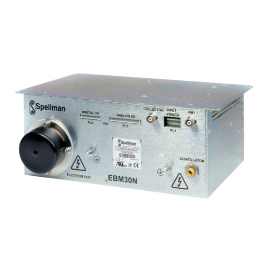
Page 5 of 16 Description The EBM30N/TEG consists of one chassis containing a complete high voltage power supply to power the main components within a Scanning Electron Microscope (SEM). The chassis is approximately 105mm x 190mm x 250mm. Rated Outputs... -
Page 6: Block Diagram
0°C but with an extended warm up period. Storage Temperature: -20°C to +75°C Humidity: 0% to 85% RH (non-condensing) EBM30N/TEG – Installation and User Guide Document Number: 81773-4 Issue: 2 Spellman High Voltage Electronics Limited | +44 (0)1798 877000 | hvsales@spellmanhv.co.uk... -
Page 7: Safety
SYMBOL MEANING Refer to manual before operating Caution, possibility of electric shock Protective conductor terminal (PE) Functional Earth EBM30N/TEG – Installation and User Guide Document Number: 81773-4 Issue: 2 Spellman High Voltage Electronics Limited | +44 (0)1798 877000 | hvsales@spellmanhv.co.uk | Broomers Park, Pulborough, W. -
Page 8: Installation Of The Hv Unit
The mechanical outline of the unit is shown in Appendix 1 – EBM30N/TEG Outline Drawing. The EBM30N/TEG must be fitted in a unit and secured in position using the mounting brackets provided. A safety interlock should be used to prevent access to the unit when it is operating. -
Page 9: Control Connectors - Pl2 And Pl3
LOW <0.5V at ≤1.6mA Filament OC return HIGH >2.5V at ≤-180uA Not Used Not Used Not Used EBM30N/TEG – Installation and User Guide Document Number: 81773-4 Issue: 2 Spellman High Voltage Electronics Limited | +44 (0)1798 877000 | hvsales@spellmanhv.co.uk | Broomers Park, Pulborough, W. Sussex, UK. RH20 2RY ©... -
Page 10: Input Power And Control Connectors Accessory Kit
Claymount (www.claymount.com) can also provide mating cable assemblies terminated with mini75 high voltage plug. Spellman can provide a cable assembly in different lengths, terminated one end in the mini 75 and the other end open. Drawing is shown in Appendix 2 - HV Cable Assembly... -
Page 11: Scintillator Output And Cables
3.3.5. Scintillator Output and Cables This uses a bespoke ’Poke home’ receptacle manufactured by Spellman HV with an 9mm ISO metric thread, 39mm deep. See drawing in Appendix 3 – Scintillator Cable Assembly. Different lenghts scintillator mating cables for the ‘Poke home’ receptacle are available to order. -
Page 12: Operation Of The Hv Unit
Page 12 of 16 Operation of the HV Unit Control Signals The EBM30N/TEG unit is controlled by analogue and digital inputs using the two signal I/O connectors shown in Section 3.3.2 The following table details the action of each control signal. -
Page 13: Protection
All low voltage inputs are protected against over voltage (up to 30V) and negative input voltages (up to -30V). The maximum output voltage, even under single fault conditions, is 40kV. EBM30N/TEG – Installation and User Guide Document Number: 81773-4 Issue: 2... -
Page 14: Appendix 1 - Ebm30N/Teg Outline Drawing
Page 14 of 16 Appendix 1 – EBM30N/TEG Outline Drawing... -
Page 15: Appendix 2 - Hv Cable Assembly
Page 15 of 16 Appendix 2 - HV Cable Assembly... -
Page 16: Appendix 3 - Scintillator Cable Assembly
Page 16 of 16 Appendix 3 – Scintillator Cable Assembly...
Need help?
Do you have a question about the EBM30N/TEG and is the answer not in the manual?
Questions and answers