Table of Contents
Advertisement
Quick Links
GENERAL INFORMATION
The 4219 expander module adds up to eight normally closed or eight end-
of-line resistor supervised zones to compatible control/communicators via
the control's keypad wiring.
The module may be mounted within the control's cabinet (if room permits),
or remotely. If mounted remotely, there are provisions to tamper protect
the unit. Communication to the module is supervised so that it cannot be
disconnected from the keypad wiring without detection by the control. If
the wiring is cut, a tamper alarm or signal will result, to indicate that this
device (and possibly other similarly connected devices) has become
inoperative.
IMPORTANT: Some carbon monoxide detectors may not be compatible
with the l 4219 hardwire zone expanders. When using carbon monoxide
detectors in systems that support the 4219 zone expanders, install the
detectors only on the basic hardwire zones of the system control panel,
and NOT on the zone expanders.
INSTALLATION
1. Disconnect power before proceeding.
2.
Mount the 4219 before making any wire connections.
When the module is mounted remotely, holes on the back of the module's
housing permit it to be mounted horizontally or vertically. Wires can exit
from the side or the breakout on the back of its housing. For tamper
protection, attach the tamper magnet (provided) (Figure 1) to the module
inside cover. Place DIP switch position #8 in the OFF position. Affix the
connections label that accompanies the module to the inside of the module's
cover. When the installation is complete, put the modules cover on. The
magnet attached to the cover, positioned near the reed switch, will cause a
tamper signal to be sent to the control if the cover is removed.
When the module is to be mounted inside the control's cabinet, mount it
horizontally to the raised tabs at the back of the cabinet. Insert self-tapping
screws (provided) in two adjacent raised tabs at the back of the cabinet.
Leave the heads projecting 1/8". Hang the module on the screw heads via
two slotted holes on the back of the module's housing. When the module is
installed in the control's cabinet, it need not be tamper protected.
NOTE: For EN50131-3 compliance a tie-wrap must be secured around
the case of a remotely mounted 4219. Apply tie-wrap around the
case to the right of the large zone wire opening (4-inch case
width). This is in opposition of the tamper switch and magnet.
NOTE:
ADDRESSES 16-31 MAY
NOT BE AVAILABLE; CONSULT
THE HOST CONTROL PANEL
INSTALLATION INSTRUCTIONS.
DETAIL A
IF EOLR OPTION SELECTED, TERMINATE EACH PROGRAMMED ZONE WITH 2K OHM END-OF-LINE RESISTOR
(EACH ZONE'S MAX. LOOP RESISTANCE: 300 OHMS + EOL). IF NORMALLY CLOSED OPTION SELECTED,
CONNECT ALL ZONES AS NC LOOPS. SEE DETAIL A
U L
For UL, use 14-22AWG wire, and no more than one wire may be connected per terminal. Use UL Listed EOL resistors.
Installation and Setup Guide
Figure 1. Tamper Magnet Installation
8 7 6 5 4 3
2 1
REED (TAMPER) SWITCH
TB1
1
2
3
1
2
3
TB1
ZONES A
B
ZONES A
B
Figure 2. Summary of Connections
EOLR value is 2K ohms.
Affix the connections label that accompanies the module to the inside of
the control's cover. See the control's installation and setup guide for
additional information.
CONNECTIONS AND SETTINGS
Zone Connections
Make protection zone connections to the module's 12-position terminal
block TB1.
Set DIP switch 7 for the desired zone operation (NC or EOLR):
OFF =
End of line resistor operation. Each zone that is used must have
a 2K-ohm end-of-line resistor connected across the end of its
loop, as shown in Figure 2.
UL: Set to OFF (EOLR)
ON =
Normally closed operation
The method of programming each zone for the type of alarm and reporting
code to the central monitoring station varies with the control to which the
module is connected. Refer to the Installation and Setup Guide for that
control unit.
Module Address
Set the module address using DIP switches 2-6.
Select one of 31 addresses, as shown in Figure 3, so the control can identify
the module and communicate with it properly. The address to be set is
determined by the particular control to be used, and the control's installation
instructions must be consulted.
Normal/Fast Response Time for all zones
Use DIP switch 1 to select normal or fast response time for all zones:
OFF =
fast response time of 10ms to an open circuit
ON =
normal response time of 300ms. All other module protection zones
have a nominal response time of 300ms.
Connection to the Control Panel
Connect the module to the control panel's keypad (ECP) terminals via 4-
terminal block TB2 or the 4-pin plug (wire color connections are the same).
SPECIFICATIONS
Physical .... 6-7/16"W x 4-1/4"H x 1-1/4" D (163mm x 108mm x 32mm)
Electrical
Input Voltage:12VDC (from control's remote keypad connection points)
Current: ....................................................................................... 30mA
1. INSERT BOTTOM TABS FIRST.
2. ENGAGE TOP WITH CLIP.
DIP SWITCH
4-PIN CONSOLE
PLUG
CONNECTIONS
SAME
AS TB2
4
6
8
5
7
9
10
11
12
C
D
E
F
G
H
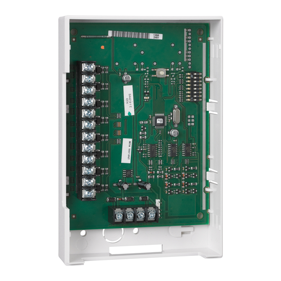
Wired Zone Expander Module
4219-002-V0
4219
1
2
3
4
GRN
DATA OUT TO CONTROL
4
BLK (–) GROUND
3
RED (+) 12VDC
2
YEL
DATA IN FROM CONTROL
1
TB2
4219
Advertisement
Table of Contents

Related Manuals for Honeywell Home 4219


Summary of Contents for Honeywell Home 4219
- Page 1 Wired Zone Expander Module Installation and Setup Guide GENERAL INFORMATION The 4219 expander module adds up to eight normally closed or eight end- Affix the connections label that accompanies the module to the inside of of-line resistor supervised zones to compatible control/communicators via the control’s cover.
- Page 2 For the latest warranty information, please go to: www.security.honeywellhome.com/warranty The Honeywell Home Trademark is used under license from Honeywell International Inc. This product manufactured by Resideo Technologies, Inc. and its affiliates 2 Corporate Center Drive, Suite 100 P.O. Box 9040, Melville, NY 11747 ©...
Need help?
Do you have a question about the 4219 and is the answer not in the manual?
Questions and answers