Table of Contents
Advertisement
Quick Links
Advertisement
Table of Contents

Summary of Contents for CRUISING ELECTRONICS E-Meter
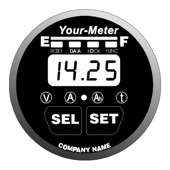
- Page 1 Copyright 1995-1998 Manual Part # 890015 Rev.5D 1/15/98 Patented Graphic and Digital Displays! The Ultimate battery monitor for..Marine Systems ...Alternative Energy Systems ...Recreational Vehicle Systems ...Industrial Lift Truck Applications ...Electric Vehicles and many more! EINSTAL5D.PM6...
- Page 2 DO NOT INSTALL OR USE THIS PRODUCT UNTIL YOU HAVE READ THE ENTIRE OWNER’S MANUAL. IMPROPER INSTALLATION OF THIS UNIT MAY BE HAZARDOUS AND VOIDS YOUR WARRANTY. Reading the Bar Graph, 19 Advanced Functions, 30-38 Removing, 11 Battery Basics, 8 Reset and Lock, 28 Declaration of Conformity, 51 Charge Efficiency Factor, 23...
- Page 3 Voltage: For 12V - 24V systems. Optional Prescalers extend voltage range. Standard Model: Two Auto-ranges: 0 to 19.95V (0.05V resolution) 20.0 to 50.0V (0.1V resolution) Optional Prescalers: 0-100V, 0-500V (Used with standard model) Amperage: Low Range: + 0 - 40.0 Amps (0.1 Amp resolution) High Range: + 500 Amps (1 Amp resolution) Amp-hours: Low Range: +0 - 199.9 Amp-hours (0.1 Amp-hour resolution)
- Page 4 The 500 A 50mV shunt senses cur- rent in or out of 2 Amp Your Meter works your battery. Fuses with flooded or gel lead-acid batteries 1 2 3 4 5 6 7 1 2 3 4 5 6 7 1 2 3 4 5 6 7 1 2 3 4 5 6 7 1 2 3 4 5 6 7...
-
Page 5: Status Lights
The Light Bar The light bar shows state-of-charge at a glance. Here's what the lights mean: FULL EMPTY Full 80-99% + 60-79%+ 40-59%+ 20-39%+ 0-19%+ Status Lights For shortest charging times, Shows what number is lead acid battery in marine or being displayed RV service is normally dis- charged 50% then recharged... - Page 6 Amps Amp-hours Amps is the present flow Amp-hours consumed of current in or out of your represents the amount battery. For example, a re- of energy removed frigerator may draw 6.2 from the battery. If you Amps of current. This is run a 10 Amp load for displayed as (6.2...
- Page 7 Time of operation remaining until recharging is required. This meter is sold under a variety of brand names: Cruising Equipment Company meters are called an E-Meter . Heart Interface units are la- beled Link 10. Other companies have private brand names for this prod- uct.
- Page 8 Why monitor a battery? Batteries can be ruined by excessive discharge. They may also be dam- aged by under-charging. A battery (or bank of batteries) may be storing less energy than you think. Your Meter provides all the key data you, or your technician, need to make decisions about battery use and charging.
-
Page 9: Installation Planning
Basic installation of Your Meter on a 12 or 24 Volt system involves only 5 wires. Because Your Meter will work on systems up to 500 Volts, special high voltage installation techniques are discussed beginning on Page 44. You need to read this section if you're working on an electric vehicle or system where more than 50 Volts is encountered. - Page 10 Our Patent Pending "Ratchet Ring" makes mounting easy and fast . TIP: When installing from the front of a panel or dashboard slide the Ratchet Ring CAUTION! onto cable with correct orientation Orient ring so the ratchet and then connnect teeth will engage properly.
- Page 11 Removing Your Meter is the reverse of mounting with a TWIST as shown in the following diagrams. Twist 1/8th turn to unlock teeth. Then pull lock ring straight back as shown below. Pull both sides of the lock ring equally Patented...
-
Page 12: Installation Tip
This drawing is for 12V & 24V systems. For higher voltages see Prescaler use on Page 44. Fuses Shunt Twisted pair cable (system ground) See Detail Page 13 Terminal Strip INSTALLATION TIP: Connections Use appropriate strain relief to See Detail Page 14 avoid damage to the connector and terminal strip on the rear of Mounting Page 10... - Page 13 The shunt is the current sensor for Your Meter. Its 500A 50mV rating means that when 500 Amps flows through it there is 50mV generated across it. The millivolt signal is translated into an Amps display in the meter. For example: A 50A load would generate 5mV across the shunt and would be displayed as Amps.
-
Page 14: Top Rear View
Make the necessary wire connections to Your Meter as shown in the following diagram: Color code shown for CECO 4 twisted pair cable. Part #s below: PN 910007 -15' PN 910009 -25' PN 910010 -50' CAUTION Use correct sized screwdriver for terminal screws. - Page 15 Most failures and problems are due to wiring errors. Please double check the wiring. (Color code shown is for CECO wire Part #s on Page 14.) - DC Power (Black Wire). Start at terminal #1 of the meter and follow it to the big bolt on the Load side of the shunt.
-
Page 16: Factory Default Settings
Once you have completed ALL instructions on Page 17, insert the voltage sense wire fuse, then the meter power fuse. (BLUE wire fuse first, RED wire fuse last!) The fuse should be in a fuse holder and should be connected in a smooth motion. - Page 17 Synchronize Your Meter to a full battery. After installing Your Meter, charge the battery until the far right Green LED begins flashing, which indicates the Charged Parameters have been met. Amp-hours will have started at and counted up as a positive num- ber.
- Page 18 Although Your Meter is a very sophisticated device, obtaining basic battery information from it is simple. With the unit turned on and the (Volts) LED on, let's learn how to display the four most important DC system parameters . When you touch the button, you ecting the display you wish.
- Page 19 Above the digital display are four LEDs. They tell you the battery's state- of-charge at a glance. Four green LEDs means your battery is full. One flashing red light means it's nearly discharged. The table below shows the six different displays indicating battery state-of-charge. Under certain light conditions green may appear yellow.
- Page 20 Pressing and holding the SET button for 3 seconds enters the Set Up and Advanced Functions mode. The word SEL apppears in the display, prompting you to press the SEL button to choose what function you want to SELect. Pressing SEL chooses a variable or function. The SET UP mode always begins (Volts) function.
- Page 21 The first time you use Your Meter, it assumes you have 200 Amp-hour lead acid batteries. If your battery capacity is different you must change the declared battery capacity. Follow these instructions to declare a new capacity: Press and hold the SET button for 3 seconds to enter SET UP (and Ad- vanced Functions) menu.
- Page 22 Your Meter depends on the Charged Parameters to stay in sync with the battery state-of-charge, to automatically reset to Zero, and to automatically calculate the CEF. The default settings are for 12V lead acid (liquid or gelled) batteries. They have been carefully chosen to work on most systems, including constant voltage and multiple step charging systems.
- Page 23 If you change the Charged Parameters please use the following rules. The Charged Voltage Parameter MUST BE AT LEAST 0.1V BE- LOW the voltage at which the charging system finishes charging. Example: If your charging system finishes the battery at 13.8 Volts, a Charged Voltage Parameter of 14.0 Volts will not work.
- Page 24 Five different displays are available in the Time function. You may select present consumption level, a four minute average, a sixteen minute, or a 32 minute average, or display the percent of rate compensated capacity remaining. Which method is best for you depends on your installation. Most installations will find four minute averaging appropriate.
- Page 25 Your Meter may support an optional two wire temperature sensor. The temperature sensor is activated by turning Advanced Function F16 ON. With F16 ON, F03 shows battery temperature in degrees Celcius. When activated, F03 will continue to display temperature after exiting the Set Up mode until one of the two front panel buttons, SET or SEL is pressed.
- Page 26 Peukert's Exponent is a number which describes how battery capacity shrinks as the rate of discharge is increased. Your Meter uses a number between 1.00 and 1.50 to describe how fast a particular battery will "shrink" when a heavy load is connected. A more complete technical discussion of the Peukert Expo- nent, and typical value tables is included on Pages 48-41.
- Page 27 Two Types of Alarms Your Meter is equipped with both a visual Power Loss Alarm and a visual Low Battery Alarm. It is important that you understand the difference between these functions. Power Loss Alarm: Shows when power being supplied to Your Meter has dropped to an unsafe level.
-
Page 28: Front Panel Locking
In addition to reporting primary system values, Your Meter is capable of many other front panel functions and will also display important historical battery data. The words below the bar graph display indicate which of these functions you are accessing. To use these functions you must read and understand the following section of this manual. - Page 29 Key Battery Data Displayed DATA Key historical battery information is available through this function. Each time the SEL button is pressed while in the DATA mode the next piece of data is displayed. Select DATA as previously described to see DATA. CEF (Displayed as ): The Charging Efficiency Factor (CEF) is displayed.
-
Page 30: Advanced Functions
Advanced Functions FUNC Allows setup of Advanced Functions. To access the FUNC mode, SELect the FUNC mode as previously described. The letters F0i will appear in the display and the FUNC LED will be lit indicating you are in the FUNC mode. Continue pressing the SEL button until the function you wish to setup appears. - Page 31 F03 DISPLAY OR SET BATTERY TEMPERATURE If there is no external temp sensor and F-16 is OFF (factory default), this function sets ambient battery temperature used to caluculate rate corrected battery capacity which drives the LED bar graph and the Time remaining display.
- Page 32 F06 MANUALLY SET CEF (Not Recommended) Allows manual set up of CEF. Displayed as two digits. Default display indicates automatic CEF recalculation feature active. Returning to from a user CEF turns the automatic CEF feature back on. If a user set up in the DATA mode.
- Page 33 CAUTION: If you set the discharge floor high, such as 50%, and continue to discharge well beyond this point, you will notice that the bar graph does not "fill up" until you have charged the battery above the discharge floor. In other words, if you set the discharge floor at 50% and discharge 75%, you must recharge back up to the 50% level before your bar graph and time of operation will again give you meaningful information.
- Page 34 F16 TEMPERATURE SENSOR ON/OFF This function turns the optional external temperature sensor on or off. This feature is only operable when a temperature sensor has been connected between Pin 6 and Pin 8 of Your Meter. To fully understand this feature, please refer to F03 on pages 34-35 of this document.
-
Page 35: Visual Alarm Indication
Units with serial numbers greater than 005000 allow access to an enhanced Low Battery Alarm feature. To activate this feature, change Function F14 to ON. When F14 is ON, Your Meter displays a visual alarm when the monitored battery meets either of two conditions: 1) A settable rated compensated (Peukert) Amp-hour depth of discharge is exceeded or, 2) Voltage remains below a settable level for 15 seconds or longer. - Page 36 Refer to F14 in the Owner's Manual Functions F10, F11, and F12 define operation of the Visual Low Battery Alarm as follows: F-11 F-10 TURNS OFF Low TURNS ON Low Bat- Battery Alarm when tery Alarm at a set % AHrs are restored of rate compensated AHrs Discharged...
-
Page 37: Things To Remember
NOTE: The Low Battery Alarm ON and OFF points oper- ate on rate compensated (Peukert) Amp hours consumed. Once the alarm is activated, the battery must be charged until Alarm OFF Set Point is reached to turn the alarm off. F12 LOW VOLTAGE ALARM THRESHOLD F-12 sets the Voltage below which the Low Battery Alarm is activated. -
Page 38: Audible Alarm
Special versions of Your Meter are available, for additional charge, which include a solid state Alarm Switch to ground via rear panel terminal strip Pin #7. This option is use in a variety of settings such as lift pump lock out on fork lifts, two wire generator start/stop, audible low battery alarms, and charge controllers. - Page 39 Peukert's Equation describes the effect of different discharge rates on bat- tery capacity. As the discharge rate increases the available battery capac- ity decreases. The table and examples on the following page illustrate this effect and how to use the table to estimate the exponent "n". The tables on pages 34 &...
- Page 40 The table below may be used to understand the effect of high rates of discharge on available battery capacity. It may also be used to estimate the exponent "n" for a battery after a single discharge test. The table is based on a 100 Ahr battery but may be used for any capacity battery by using an appropriately scaled current.
- Page 41 Typical Values for Peukert's Exponent "n" This table contains values for the exponent "n" for various batteries and manufactures. They are calculated from the 20 hour rating and the Re- serve Minutes @ 25A as supplied by the manufacturer. They should be considered only a guide for selecting "n".
- Page 42 Surrette and Rolls Batteries Model Volts Res. Min. 20 Hr. rating "n" EHG-208 1.42 EIG-225 1.54* EIG-262 1.72* 24/90 1.16 27/12M 1.23 30H/108 1.08 HT/4D 1.15 HT/8D 1.20 *Use Max allowed "n" of 1.50 Example of using Reserve Minutes @ 25 Amps and the 20 hour rate to calculate "n".
- Page 43 Condition Suggestion No lights or display Check Power Connections Reset meter (Page 32) No keyboard response Check Lock is not invoked Reset meter (Page 32) Time Remaining Not Check Battery Capacity (Page 21) Accurate Check Temperature Coef. (Page 35) Check Peukert Exponent (Page 26) Digital Display Dim Clean front panel photo-sensor (Between A and Ah lights)
- Page 44 User installable OPTIONS available include: Prescalers: Extend the voltage range covered by Your Meter to either 0-100V (CECO Part #900087) or 0-500V (CECO Part #900086). Temperature Sensor: Reports battery temperature in Degrees Celcius (CECO Part #900105) All other options must be installed at the time Your Meter is manufac- tured as additional circuitry is involved.
- Page 45 Installation of the Prescaler Option involves work with poten- tially fatal voltages. NEVER work alone: Have at least one person present who can render assistance and CPR in the event of an acci- dent. If you have any doubt about your qualifications to work on a high voltage system, DON'T DO IT! When working with any DC system, even so-called ungrounded ("floating") systems with no planned chassis connection, discon-...
- Page 46 Your Meter is the ideal energy meter for EV instrumentation. It not only provides Volts, Amps, Amp-hours and Time Remaining, it adds two im- portant bonuses: Kilowatt-hours and optional serial computer output. If you design or work with electric vehicles or battery powered equip- ment of any type, you should realize that Kilowatt-hours are a more accu- rate measure of energy used than are Amp-hours.
- Page 47 The negative of Your Meter's power supply must be common to the nega- tive of the battery (motive pack) which you are measuring. This may pose difficulty if your electric vehicle uses an "unbonded" or "floating" [no connection to the chassis] motive pack and a "bonded" [connected to the chassis] accessory battery.
- Page 48 Installation of Your Meter in Lift Trucks, which have the motive pack bonded to the chassis and also have a 12V accessory battery bonded to the chassis, may use the diagram below for proper wiring of the appropriate Prescaler. The 0-100V Prescaler is used where system voltage does not exceed 100V at any time including during onboard charging.
-
Page 49: Output Format
Your Meter may be equipped to transmit serial communications data to a per- sonal computer or a data logging device, such as our Memory Module. When equipped with the optional RS-232 port, Your Meter will transmit a data mes- sage once a second. The structure of this data is as follows: Data Rate: 9600 Data Bits:... - Page 50 HOW TO SET VOLTAGE SCALING WHEN USING A HIGH VOLTAGE PRESCALER F13 SET VOLTAGE SCALING Sets proper voltage scaling when used with an external Voltage Prescaler. NOTE: If you use a Prescaler, you need to change the Charged Voltage to an appropriate value for your application. See Pages 21 &...
- Page 51 Manufacturer: Cruising Equipment Co. Address: Cruising Equipment Co. 5245 Shilshole Ave. NW Seattle, WA 98107 U.S.A. Herewith declares that: E-Meter Battery State of Charge Meters Models: E-Meter Link 10 Battery Monitor DCM-1000 Energy Manager Checkmate Batt-Meter Is in conformity with the provision of the EEC Directive EMC 89/336/EEC and amendments 92/31/EEC, 93/68/EEC.
- Page 52 The purchase of Your Meter includes one 15 minute phone call. You must have a serial number to access the service department. Subsequent calls will be billed at $1.00/minute with a $15.00 minimum. Please have your Mastercard or Visa ready. This policy is strictly enforced in an effort to keep the product cost as low as possible.
- Page 53 When using an RS-232 equipped version of Your Meter in an electric vehicle which has a floating motive battery negative, re- member that Pin #5 of the DB-9 connector coming out of the back of Your Meter is connected to the motive battery negative. This normally causes no problem when used with our Memory Modules or with laptop computers.
- Page 56 If you can drill 1 hole... Connect 5 wires..Follow a few simple instructions..You can have the Ultimate Battery Monitor! 5245 Shilshole Ave. NW, Seattle, WA 98107 U.S.A. Phone: (206) 782-8100 Fax: (206) 782-4336 Visit our web site at: http://www.cruisingequip.com...
Need help?
Do you have a question about the E-Meter and is the answer not in the manual?
Questions and answers