Table of Contents
Advertisement
Quick Links
Instruction Manual
Electronic Switch
TOE 9261
9261E-Manual-Rev05.doc
R
TOELLNER ELECTRONIC INSTRUMENTE GMBH
Gahlenfeldstraße 31, 58313 Herdecke, Germany
+49 (0) 23 30 - 97 91 91 • Fax +49 (0) 23 30 - 97 91 97
E-Mail: info@toellner.de • Web:
www.toellner.de
Subject to technical changes
TOELLNER Electronic Instrumente GmbH
22.11.2017
Advertisement
Table of Contents

Related Manuals for TOELLNER TOE 9261

Summary of Contents for TOELLNER TOE 9261
- Page 1 Instruction Manual Electronic Switch TOE 9261 9261E-Manual-Rev05.doc TOELLNER ELECTRONIC INSTRUMENTE GMBH Gahlenfeldstraße 31, 58313 Herdecke, Germany +49 (0) 23 30 - 97 91 91 • Fax +49 (0) 23 30 - 97 91 97 E-Mail: info@toellner.de • Web: www.toellner.de...
-
Page 2: Table Of Contents
Configuring for 19" rack mount ................16 19" adapter set (2 HU) for 1x TOE 9261 (option) ..............16 19" adapter set (2 HU) for two Toellner Instruments ½ 19" (option) ........17 Technical data ....................... 18 Technical data TOE 9261 ....................18 General data ........................ - Page 3 Qualified personnel according to this manual are persons who are familiar with the assembly, startup and operation of the devices and who possess the corresponding qualifications for their work activity. TOELLNER Electronic Instrumente GmbH...
-
Page 4: Introduction
Section 1 – Introduction Introduction The electronic switches of the TOE 9261 series are used for time-specific switching on and off of load and signal currents. These devices use an electronic, unidirectional power switch as well as four electronic bidirectional signal line switches. The power switch can be used either to switch a positive supply line or to switch the return line, e.g. -
Page 5: Overview Of Features
- Protected against overcurrent / short-circuit, excessive temperature, excessive switching frequency Model overview Series TOE 9261 devices are available in models for various rated currents. The rated current of the power switch is indicated by a hyphenated number added to the basic part number. -
Page 6: Operation
( 2.6.4 Excessive temperature protection). Series TOE 9261 devices are designed so that they can be used either as tabletop units or in 19" rack systems. Appropriate adapters for 19" rack use are available as an option. -
Page 7: Description Of The Controls
Description of the controls At the end of the manual you will find the various operating and display elements for the series TOE 9261 numbered with front panel and rear views. In the following the individual operating elements are explained in detail. - Page 8 Terminal block for signal line switches S3 and S4. These can be used with suitable [14] terminal block plugs ( 4.1 Technical data TOE 9261, Connections, Signal line switches). The control and signal lines to be switched are routed through the signal line switches indicated by the switch symbols S3 and S4.
-
Page 9: Rear Panel Controls
LEDs. Switching time settings are made on the clock source used (e.g. function generator), which may if desired be connected to the front or rear BNC input CONTROL on the TOE 9261. Power switch operation 2.4.1... -
Page 10: Connection Of The Consumer For Switching The Positive Supply Line
In the described switch configuration, the negative return line must always be connected from the consumer to the voltage source via the minus sockets of the TOE 9261. These minus sockets must never be bypassed, because otherwise some protection mechanisms of the Electronic Switch are without effect, and damage to the Electronic Switch may result. -
Page 11: Display Of The Switching States
S2 + 0 Ω is set to ( 2.4.9 Use of the branch path). TOE 9261 and consumer were connected in the configuration for switching the return line (ground), and the DIL switch was not set to S1 ENABLE... -
Page 12: High-Impedance Base Load
The current which is drawn by the consumer during the turn-on phase of the PWM is allowed to have values up to the rated current of the TOE 9261. If the current draw is higher, the overcurrent protection on the TOE 9261 may be triggered during the turn-on phase of the PWM. -
Page 13: Operation Of The Signal Line Switches
The upper limit of the applied signal levels is limited to the rated voltage of the TOE 9261. The electrical isolation between the signal line switches and to the CONTROL input is for up... -
Page 14: Protection
Feedback from the (buffered) load side to the OUT output of the power switch must have the indicated polarity and not exceed the rated voltage of the TOE 9261, i.e. the voltage connected to OUT must not be more positive than the voltage at the Plus sockets or more... -
Page 15: Excessive Temperature Protection
If the component temperatures continue to rise, the internal driver stages are shut off, i.e. the switching paths are no longer driven. This fault condition is indicated by the OVL LED. After an appropriate cool-down time the unit can be reset by turning it off and on using the mains switch. TOELLNER Electronic Instrumente GmbH... -
Page 16: Configuring For 19" Rack Mount
The series TOE 9261 Electronic Switches are 19" rack-capable tabletop devices. By using the optional TOE 9521 one TOE 9261 can be easily converted for 19" 2 HU rack mount. The optional 19" adapter set TOE 9521 includes a 19" adapter piece with handle and a 19"... -
Page 17: 19" Adapter Set (2 Hu) For Two Toellner Instruments ½ 19" (Option)
19" adapter set (2 HU) for two Toellner Instruments ½ 19" (option) The series TOE 9261 Electronic Switches are 19" rack-compatible tabletop devices. By using the optional TOE 9522 two Toellner Instruments ½ 19" (2 HU) of equal length can be easily converted for 19" 2 HU rack mount. -
Page 18: Technical Data
Section 4 – Technical Data Technical data Note The technical data are based on a warm-up time of at least 30 minutes under constant conditions and a reference temperature of 23°C ±1°C. Technical data TOE 9261 Model TOE 9261-50 TOE 9261-100 Input voltage... - Page 19 Phoenix MC 1.5 / 4-ST-3.81 = Article No. 1803594 Würth Elektronik plug-in cable system WR-TBL Series 361 = Article No. 691361300004 Electrical isolation Between power switch, signal line switches, control input and PE, max. 42 V each peak TOELLNER Electronic Instrumente GmbH...
-
Page 20: General Data
1.20 m connection cable with 1 safety socket, blue .......... TOE 9260/25 19" adapter set 2 HU (asymmetrical) for 1x TOE 9261 ........TOE 9521 19" adapter set 2 HU (parallel connector) for 2 Toellner Instruments ½ 19" ..TOE 9522 Specification of the high-current connectors... -
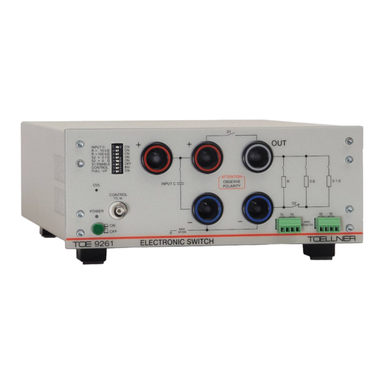
Page 21: Views
Section 5 – Views Views Front panel view of the TOE 9261 [1] Mains switch with green POWER LED [9] Power switch, branch path incl. red indication LED [10] 0 Ω series resistor for branch path with green [2] 8x DIL switch...
Need help?
Do you have a question about the TOE 9261 and is the answer not in the manual?
Questions and answers