Table of Contents
Advertisement
Quick Links
CAUTION, MICROWAVE RADIATION ....................................................................................................... 1
WARNING .................................................................................................................................................... 1
PRODUCT SPECIFICATIONS ................................................................................................................... 2
GENERAL IMPORTANT INFORMATION ...................................................................................................3
APPEARANCE VIEW ................................................................................................................................. 3
OPERATION SEQUENCE .......................................................................................................................... 4
FUNCTION OF IMPORTANT COMPONENTS .......................................................................................... 5
SERVICING ................................................................................................................................................ 7
TEST PROCEDURE ................................................................................................................................. 10
TOUCH CONTROL PANEL ASSEMBLY .................................................................................................. 17
COMPONENT REPLACEMENT AND ADJUSTMENT PROCEDURE ..................................................... 22
MICROWAVE MEASUREMENT .............................................................................................................. 27
TEST DATA AT A GLANCE ......................................................................................................................28
WIRING DIAGRAM ................................................................................................................................... 29
PICTORIAL DIAGRAM ............................................................................................................................. 31
CONTROL PANEL CIRCUIT ..................................................................................................................... 32
PRINTED WIRING BOARD ....................................................................................................................... 34
PARTS LIST ............................................................................................................................................. 35
SERVICE MANUAL
MODELS
In interests of user-safety the oven should be restored to its original
condition and only parts identical to those specified should be used.
TABLE OF CONTENTS
SHARP CORPORATION
COMMERCIAL
MICROWAVE OVEN
R-2275
R-2285
R-2275
R-2285
SY307R2395H//
Page
Advertisement
Table of Contents

Related Manuals for Sharp R-2275


Summary of Contents for Sharp R-2275
-
Page 1: Table Of Contents
R-2275 R-2285 SERVICE MANUAL SY307R2395H// COMMERCIAL MICROWAVE OVEN R-2275 MODELS R-2285 In interests of user-safety the oven should be restored to its original condition and only parts identical to those specified should be used. TABLE OF CONTENTS Page CAUTION, MICROWAVE RADIATION ....................... 1 WARNING .............................. -
Page 2: Caution Microwave Radiation
R-2275 R-2285 CAUTION MICROWAVE RADIATION Personnel should not be exposed to the microwave energy which may radiate from the magnetron or other microwave generating devices if it is improperly used or connected. All input and output microwave connections, waveguides, flanges and gaskets must be secured. -
Page 3: Warning
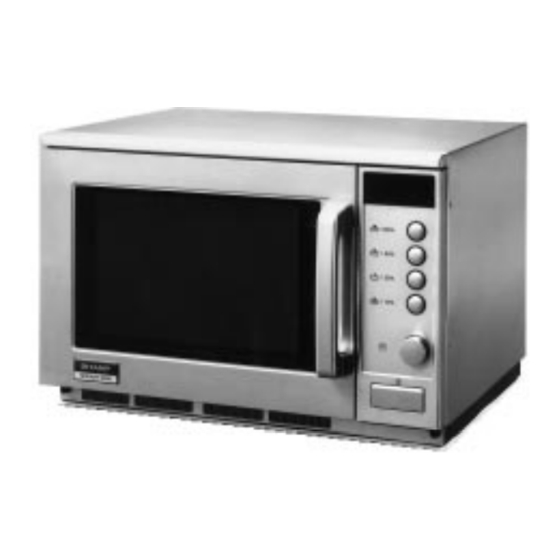
R-2275 / R-2285 GENERAL INFORMATION GENERAL IMPORTANT INFORMATION APPEARANCE VIEW This Manual has been prepared to provide Sharp Corp. Service engineers with Operation and Service Information. It is recommended that service engineers carefully study the OPERATING SEQUENCE entire text of this manual, so they will be qualified to render satisfactory customer service. - Page 4 Power Consumption 2.0 kW Approx. 9A (R-2275) 2.7 kW Approx. 13A (R-2285) Power Output 1200 watts (R-2275) / 1800 watts (R-2285) nominal of RF microwave energy (Method of IEC 705). Operating frequency of 2450MHz Outside Dimensions Width 510mm Height 335 mm including foot...
- Page 5 R-2275 R-2285 APPEARANCE VIEW Control panel Stirrer cover Oven lamp Ceramic shelf (Not removable) Air intake filter Air intake openings Door Door open handle Ventilation openings Oven lamp access cover Power supply cord CONTROL PANEL POWER /100% DISPLAY AND INDICATORS Check indicators after the oven starts to confirm the oven is operating as desired.
-
Page 6: Operation Sequence
R-2275 R-2285 OPERATION SEQUENCE The circuits to the high voltage transformers T1+T2 are OFF CONDITION cut off when the 1st latch, 2nd latch, 3rd latch and stop switches SW1+SW2+SW3+SW5 are made open. The Closing the door activates all door interlock switches... -
Page 7: Function Of Important Components
R-2275 R-2285 T2: POWER TRANSFORMER T1: POWER TRANSFORMER COMMERCIAL FREQUENCY (50HZ) ASYMMETRIC ASYMMETRIC RECTFIER RECTFIER POWER OUTPUT BY MAGNETRON 1 OPERATION OF MAGNETRON POWER OUTPUT C2: CAPACITOR C1: CAPACITOR BY MAGNETRON 2 D: H.V. RECTIFIER D: H.V. RECTIFIER AC 2100V... - Page 8 R-2275 R-2285 FUSE F6.3A 250V F2 SURGE RELAYS RY-S1 AND RY-S2 AND 1. If the wire harness or electrical components are short- SURGE RESISTORS R1 AND R2 circuited, this fuse blows to prevent an electric shock or When the START key is touched the contacts of the surge fire hazard.
-
Page 9: Servicing
If the water remains cold carry out 3D checks and re- insulated screwdriver. examine the connections to the component being tested. Sharp recommend that wherever possible fault-finding is carried out with the supply disconnected. It may in, some cases, be necessary to connect the supply after... - Page 10 R-2275 R-2285 TEST PROCEDURE B B C C C D D E E POSSIBLE CAUSE DEFECTIVE PARTS PPROBLEM CONDITION “ . “ does not appear on display when power cord is plugged into wall outlet. Control panel can not accept key in.
- Page 11 R-2275 R-2285...
- Page 12 Room temperature....around 20°C Power supply Voltage..Rated voltage Water load..1000 g Initial temperature...10±2°C Heating time..23 sec. (R-2285) / 35 sec. (R-2275) P=180x∆T (R-2285) / P=120x∆T (R-2275) Measuring condition: 1. Container The water container must be a cylindrical borosilicate glass vessel having a maximum material thickness of 3 mm and an outside diameter of approximately 190 mm.
-
Page 13: Test Procedure
Measured output power The equation is “P = 180 x ∆T” for R-2285 ........P = 180 x 10°C = 180 Watts The equation is “P = 120 x ∆T” for R-2275 ........P = 120 x 10°C = 120 Watts ±... - Page 14 R-2275 R-2285 TEST PROCEDURES (CONT'D) PROCEDURE LETTER COMPONENT TEST Isolate the high voltage rectifier assembly from the HV circuit. The asymmetric rectifier can be tested using an ohmmeter set to its highest range. Contact the ohmmeter across the terminals A+B of the asymmetric rectifier and note the reading obtained.
- Page 15 R-2275 R-2285 TEST PROCEDURES (CONT'D) PROCEDURE COMPONENT TEST LETTER SPECIAL FUSE / WEAK POINT (F1) TEST CARRY OUT 3D CHECKS If the special fuse / weak point F1 is blown, there could be a shorts or grounds in electrical parts or wire harness.
- Page 16 R-2275 R-2285 TEST PROCEDURES (CONT'D) PROCEDURE LETTER COMPONENT TEST SURGE RELAY TEST CARRY OUT 3D CHECKS Disconnect the leads to terminals 1 and 6. connect an ohmmeter across the terminals 1 and 6, a reading of approximately 160 ohms should be indicated. If this is not the case then the relay coil is probably faulty and the relay should be replaced.
- Page 17 Cx ± 20% Cy ± 20% L (min) lowing table. 1.0mH 1.0µF(R-2285) / 0.22µF (R-2275) 4700pF MEASURING POINT INDICATION OF OHMMETER Between N and L Approx. 680kΩ Between terminal N and WHITW...
- Page 18 R-2275 R-2285 TEST PROCEDURES (CONT'D) PROCEDURE LETTER COMPONENT TEST 4. If incorrect readings are obtained, replace the defective switch. 5. CARRY OUT 4R CHECKS RELAY TEST CARRY OUT 3D CHECKS Remove the outer case and check voltage between Pin Nos. 5 and 7 of the connector (A) on the control unit with an A.C.
-
Page 19: Touch Control Panel Assembly
R-2275 R-2285 TOUCH CONTROL PANEL ASSEMBLY OUTLINE OF TOIUCH CONTROL PANEL The touch control section consists of the following units as 12) High Voltage Monitoring Circuit. shown in the touch control panel circuit. This circuit detects problems in the magnetron / high... - Page 20 R-2275 R-2285 DESCRIPTION OF LSI LSI(IZA539DR) The I/O signal of the LSI(IZA539DR) is detailed in the following table. Pin No. Signal Description Connected to GND. Anode (segment) of Fluorescent Display light-up voltage: -35V Vp voltage of power source circuit input.
- Page 21 R-2275 R-2285 Pin No. Signal Description INT1 Signal coming from encoder. Signal similar to R42. Pulse signals are input into INT1. INT0 Signal synchronized with commercial power source freqency. This is basic timing for all time processing of LSI. H : GND...
- Page 22 R-2275 R-2285 SERVICING 1. Precautions for Handling Electronic Components B. On some models, the power supply cord between the This unit uses CMOS LSI in the integral part of the touch control panel and the oven proper is long enough circuits.
- Page 23 R-2275 R-2285 SERVICE INFORMATION IMPORTANT: When replace the magnetron MG1 and/or MG2, the relays RY2 and RY3 on control unit must bereplaced at the same time. CAUTION FOR TOUCH CONTROL PANEL REMOVAL 1. Hold the lower end (Position A, Fig. 1) of the touch control panel ass’y firmly while sliding it down and toward you.
-
Page 24: Component Replacement And Adjustment Procedure
R-2275 R-2285 COMPONENT REPLACEMENT AND ADJUSTMENT PROCEDURE WARNING: Avoid possible exposure to microwave energy. Please follow the instructions below before operating the oven. 1. CARRY OUT 3D CHECKS. 3. The door gasket or seal or damaged. 2. Make sure that a definite” click” can be heard when the 4. - Page 25 R-2275 R-2285 MAGNETRON REMOVAL 1. CARRY OUT 3D CHECKS. CAUTION: WHEN REPLACE THE MAGNETRON, BE 2. Carry out item 2 to item 16 of “HIGH VOLTAGE TRANS- SURE THE R.F. GASKET IS IN PLACE FORMER AND BLOWER MOTOR REMOVAL”. AND THE MAGNETRON MOUNTING 3.
- Page 26 R-2275 R-2285 POWER SUPPLY CORD REPLACEMENT 1. CARRY OUT 3D CHECKS plate with the eleven (11) screws and two (2) washers. 2. Release the cord bushing from the rear cabinet. 6. CARRY OUT 4R CHECKS. Noise filter 3. Disconnect the brown and blue wires of the power unit supply cord from the noise filter.
- Page 27 R-2275 R-2285 DOOR REPLACEMENT AND ADJUSTMENT DOOR REPLACEMENT 1. CARRY OUT 3D CHECKS 2. Remove four (4) screws holding the upper and lower oven hinge to the oven cavity. FLATE TYPE 3. Remove door assembly with upper and lower oven SCREW DRIVER hinges by pulling it forward.
- Page 28 R-2275 R-2285 HOW TO RELEASE THE POSITIVE LOCK ® CONNECTOR. Terminal Procedure ® 1. Pushing the lever of positive lock conductor. Positive lock® 2. Pull down the connector from the terminal. connector 3. Now, the connector is free. Push Note: If the positive lock ®...
-
Page 29: Microwave Measurement
R-2275 R-2285 MICROWAVE MEASUREMENT After adjustment of door latch switches, monitor switch NARDA 8100 and door are completed individually or collectively, the NARDA 8200 following leakage test must be performed with a survey HOLADAY HI 1500 instrument and it must be confirmed that the result meets the... - Page 30 High voltagr capacitor 1.07µF ( R-2285)/ 0.94µF (R-2275), AC 2100V High voltage transformer Filament winding < 1Ω Secondary winding Approx. 83Ω (R-2285) / 98Ω (R-2275) Primary winding Approx. 1.3Ω (R-2285) / 1.5Ω (R-2275) High voltage transformer Filament winding < 1Ω...
- Page 31 R-2275 R-2285 SCHEMATIC NOTE: CONDITION OF OVEN 1. DOOR CLOSED 2. " . 0" APPEAR ON DISPLAY TAB3 SCHEMATIC NOTE: CONDITION OF OVEN 1. DOOR CLOSED 2. ( )BUTTON TOUCHED 3. COOKING TIME ENTERED 4. START ( ) BUTTON TOUCHED...
- Page 32 R-2275 R-2285 SCHEMATIC NOTE: CONDITION OF OVEN 1. DOOR CLOSED 2. " . 0" APPEAR ON DISPLAY TAB3 SCHEMATIC NOTE: CONDITION OF OVEN 1. DOOR CLOSED 2. ( )BUTTON TOUCHED 3. COOKING TIME ENTERED 4. START( ) BUTTON TOUCHED TAB3...
- Page 33 R-2275 R-2285...
- Page 34 R-2275 R-2285...
- Page 35 R-2275 R-2285...
- Page 36 R-2275 R-2285 (Q60) (J10) – – E (Q24) E Q70 B – E Q23 (4) (5) DOOR E Q22 (R22,J22) – – (F1) (J7) (J9) – Figure S-4. Printed Wiring Board...
-
Page 37: Parts List
HV rectifier assembly with HVC harness assembly QFS-C0019WRE0 Weak point [R-2275] QFS-CA018WRE0 Weak point [R-2285] QFS-C0019WRE0 Weak point [R-2275] QFS-CA018WRE0 Weak point [R-2285] QFS-CA009WRE0 Special fuse 13A [R-2275] QFS-CA017WRE0 Weak point [R-2285] QFS-CA007WRE0 Fuse F6.3A ∆ RV-MZA220WRE0 Magnetron [R-2275] ∆ RV-MZA193WRE0 Magnetron [R-2285] ∆... - Page 38 15k ohm 1/4W VRD-B12EF471J Resistor 470 ohm 1/4W R22-23 VRD-B12HF390J Resistor 39 ohm 1/2W R30-31 VRN-B12EK202F Resistor 2k ohm 1/4W [R-2275] R30-31 VRN-B12EK152F Resistor 1.5k ohm 1/4W [R-2285] R32-33 VRD-B12EF102J Resistor 1.0k ohm 1/4W R34-35 VRD-B12EF304J Resistor 300k ohm 1/4W...
- Page 39 Earth angle 4-21 LBNDKA075WRP0 Capacitor holder 4-22 LANGKA679WRM0 Fixing angle S 4-23 PDUC-A499WRF0 Air duct A 4-24 PGIDHA053WRP0 Air guide E [R-2275] 4-25 PCUSGA270WRP0 Fan cushion B 4-26 LBSHC0006YBE0 Cord bushing 4-27 PZETEA070WRP0 HV cover 4-28 PRDAFA006WRP0 Radiator plate [R-2285]...
- Page 40 TCAUHA176WRR0 H caution label 6- 7 TSPCNB959WRR0 Name plate [R-2275] 6- 7 TSPCNB958WRR0 Name plate [R-2285] 6- 8 TLABS0057WRR0 Fuse label M6.3A [R-2275] 6- 8 TLABSA054WRR0 Fuse label F10A [R-2285] 6- 9 TCAUHA082WRR0 Caution label 6-10 TCAUHA083WRR0 Belgium label 6-11...
- Page 41 3. PART NO. 4.DESCRIPTION PACKING ADD KIT * CPADBA164WRK0 DOOR PROTECTION SHEET * SPADP0336WRE0 REAR PAD * SPADFA342WRE0 WRAP COVER * SSAKH0111WRE0 TRAY HOLDER * SPADFA214WRE0 PACKING CASE * R-2275: SPAKCC286WRE0 * R-2285: SPAKCC285WRE0 * Not replaceable items. PRINTED MATER INSTRUCTION BOOK...
- Page 42 R-2275 R-2285 OVEN AND CABINET PARTS 7-15 6-10 2-3-1 7-17 7-11 4-22 2-3-2 7-15 7-28 7-11 7-25 7-25 7-26 7-30 4-20 4-42 7-26 4-26 WP2 WP1 7-16 7-19 7-15 4-34 4-32 4-49 4-50 7-23 4-30 4-46 4-35 7-21 6-12 4-21...
- Page 43 R-2275 R-2285 CONTROL PANEL PARTS 3-13 3-20 3-2-3 3-10 3-2-1 3-21 3-2-2 3-17 3-19 3-18 3-22 3-16 3-14 3-11 3-15 3-12 DOOR PARTS 5 - 12 5-15 5 - 19 5 - 2 5 - 17 5-15 5 - 18...
- Page 44 R-2275 R-2285 '93 SHARP CORP. (12S1.30E) Printed in Germany...