
Related Manuals for GSi GrainVue


Summary of Contents for GSi GrainVue
- Page 1 Cable Monitoring System Installation Manual PNEG-2347 Version 1.0 Date: 11-01-21 PNEG-2347...
- Page 2 All information, illustrations, photos, and specifications in this manual are based on the latest information available at the time of publication. The right is reserved to make changes at any time without notice. PNEG-2347 Cable Monitoring System...
-
Page 3: Table Of Contents
Contents Chapter 1 Safety Precautions ........................5 Safety Guidelines ........................5 Cautionary Symbol Definitions......................6 Safety Cautions...........................7 Safety Decals ........................... 11 Operating Conditions.........................13 Maintenance and Service......................13 Safety Sign-off Sheet.........................14 Chapter 2 Gateway Installation........................15 Gateway Installation — Overview ....................15 Installing the Power Supply Unit (PSU) ..................15 Installing the Gateway .......................18 Chapter 3 Cable Monitoring Overview .....................23... - Page 4 NOTES PNEG-2347 Cable Monitoring System...
-
Page 5: Chapter 1 Safety Precautions
Safety Precautions Topics Covered in this Chapter ▪ Safety Guidelines ▪ Cautionary Symbol Definitions ▪ Safety Cautions ▪ Safety Decals ▪ Operating Conditions ▪ Maintenance and Service ▪ Safety Sign-off Sheet Safety Guidelines Safety guidelines are general-to-specific safety rules that must be followed at all times. This manual is written to help you understand safe operating procedures and problems that can be encountered by the operator and other personnel when using this equipment. -
Page 6: Cautionary Symbol Definitions
Chapter 1: Safety Precautions Cautionary Symbol Definitions Cautionary symbols appear in this manual and on product decals. The symbols alert the user of potential safety hazards, prohibited activities and mandatory actions. To help you recognize this information, we use the symbols that are defined below. Table 1-1 Description of the different cautionary symbols Symbol Description... -
Page 7: Safety Cautions
Chapter 1: Safety Precautions Safety Cautions Use Personal Protective Equipment • Use appropriate personal protective equipment: Respiratory Foot Protection Protection Protection Hearing Head Fall Protection Protection Protection Hand Protection • Wear clothing appropriate to the job. • Remove all jewelry. •... - Page 8 Chapter 1: Safety Precautions Maintain Equipment and Work Area • Understand service procedures before doing work. Keep area clean and dry. • Never service equipment while it is operating. Keep hands, feet, and clothing away from moving parts. • Keep your equipment in proper working condition. Replace worn or broken parts immediately.
- Page 9 Chapter 1: Safety Precautions Confined Space Hazards and Entry Procedures • Note that the interior of this equipment is considered a con- fined space. Maintenance of this equipment can require access to the confined space. • Access doors must be shut and locked except when access is required.
- Page 10 Chapter 1: Safety Precautions Do Not Enter Bin • Rotating flighting will kill or dismember. • Flowing material will trap and suffocate. • Crusted material will collapse and suffocate. — If you must enter the bin: 1. Shut off and lock out all power sources. 2.
-
Page 11: Safety Decals
The safety decals on your equipment are safety indicators which must be carefully read and understood by all personnel involved in the installation, operation, service and maintenance of the equipment. To replace a damaged of missing decal, contact us to receive a free replacement. GSI Decals 1004 E. Illinois Street Assumption, IL 62510 Phone: 1–217–226–4421... - Page 12 Chapter 1: Safety Precautions Description Location Decal No. Decal Warning Keep Clear of On bin door DC-GBC-1A Augers covers On bin door Warning Unload Instructions DC-GBC-2A covers GrainVue fan Danger GrainViz Fan Safety 530-00147 control Text PNEG-2347 Cable Monitoring System...
-
Page 13: Operating Conditions
Chapter 1: Safety Precautions Operating Conditions The GrainVue Cable Monitoring system has been designed to operate within the conditions outlined in Table 1-2, page 13. Do not install or operate the GrainVue Cable Monitoring system in conditions that are beyond what is listed below. -
Page 14: Safety Sign-Off Sheet
Chapter 1: Safety Precautions Safety Sign-off Sheet Below is a sign-off sheet that can be used to verify that all personnel have read and understood the safety instructions. This sign-off sheet is provided for your convenience and personal record keeping. Date Employee Name Supervisor Name... -
Page 15: Chapter 2 Gateway Installation
▪ Installing the Gateway Gateway Installation — Overview The GrainVue outdoor communications gateway system comes with a pre-built and mounted MikroTik LtAP unit. Throughout this section, various antennas will need to be installed and connected to this base unit. A Gateway Power Supply Unit (PSU) is also provided to supply power remotely to the gateway over standard, shielded category 5e data cable. - Page 16 Chapter 2: Gateway Installation What You Should Know The Gateway PSU must be installed in a location that has sufficient air circulation around the box. Minimum clearance is 22" W x 27" H to ensure protection against electrical conducted noise. NOTE: Refer to the custom site map for the recommended PSU installation location.
- Page 17 Chapter 2: Gateway Installation 3. Using four self-tapping screws (1), mount the Gateway PSU (2) onto an appropriate structure in the location designated on your custom site map. Figure 2-3 Installing the Gateway PSU Self-tapping screws Ethernet Cable Gateway PSU Power Cable 4.
-
Page 18: Installing The Gateway
The Gateway assembly can be mounted multiple ways, choose an option that is best for your site location. There are two gateway assembly variants that can be provided with GrainVue systems. Option 1 (KIT - Gateway Mounted Assembly, WiFi) is used for connection to a pre-established local WiFi network. - Page 19 Chapter 2: Gateway Installation 3. Install the ubiquiti pole (8) onto the gateway top bracket (5) using the three pre-installed U-bolt sets (9). Figure 2-6 Installing the ubiquiti pole U-bolt set Gateway top bracket Ubiquiti pole 4. Install the WiFi and cell gateway kits. a.
- Page 20 Chapter 2: Gateway Installation b. For Wifi gateway kits: Install the LPDA directional antenna (12) onto the ubiquiti pole (8) using the pre-installed U-bolt set (9). Figure 2-8 Installing the LPDA antenna Ubiquiti pole LPDA directional antenna U-bolt set 5. Remove the bottom access door of the gateway and connect all installed antennas according to the key below.
- Page 21 Chapter 2: Gateway Installation 6. The gateway bracket assembly (13) can be mounted in different positions using the provided U-bolts and ubiquiti bracket mount. See Figure 2-10, page 21 for different mounting options. NOTE: The gateway bracket assembly (13) can be mounted multiple ways, choose an option that is best for your site location.
- Page 22 NOTES PNEG-2347 Cable Monitoring System...
-
Page 23: Chapter 3 Cable Monitoring Overview
▪ System Overview Installation Overview There are multiple options for connecting the T/RH cables and supplying power to the GrainVue Cable Monitoring System. These options are outlined below. Corresponding hardware will be provided for your installation, based on the options selected at the time the system(s) were ordered. -
Page 24: System Overview
Chapter 3: Cable Monitoring Overview System Overview The parts list below outlines the primary components of the Cable Monitoring System. Figure 3-1 Cable Monitoring parts identification Table 3-1 Cable Monitoring parts list Description Quantity Ref Number Part Number Cable Monitoring Hub 074-11954 Mounting Bracket 028-00846... -
Page 25: Chapter 4 Installing The Cable Monitoring Hub
Installing the Cable Monitoring 1. Remove the wing nuts (26) that are pre-assembled on the Hub (16). 2. Align the Hub (16) with the curved slots in the mounting bracket (17) and re-install using the wing nuts (26). Figure 4-1 Assembling the Hub onto the mounting bracket Cable Monitoring Hub Wing nuts Mounting bracket... - Page 26 Chapter 4: Installing the Cable Monitoring Hub 3. Install the mounting bracket (17) and Hub assembly onto the bin roof (27) by placing the mounting bracket (17) down and allowing the pre-installed magnetic feet to attach to the bin roof (27). NOTE: The exact placement of the Hub (16) is flexible.
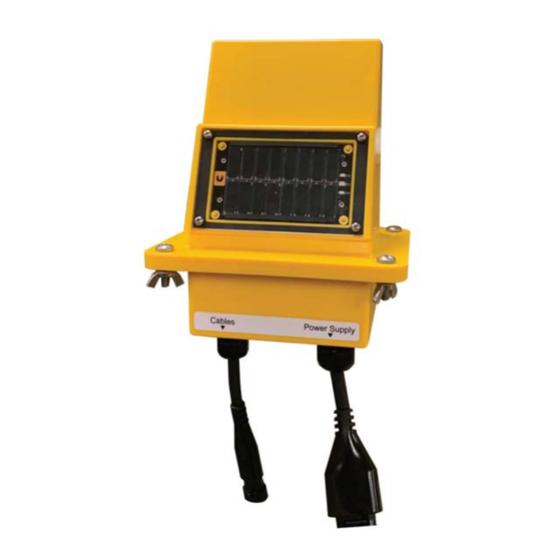
- Page 27 Chapter 4: Installing the Cable Monitoring Hub NOTE: Any two cables connected to the Cable Connection Port (28) and Power Supply Port (29) of the Cable Monitoring Hub (16) must maintain a minimum of 2" spacing throughout their entire length. Figure 4-4 Cable connection and power supply ports in the Hub Cable Monitoring Hub Power supply port (four pin connector)
- Page 28 NOTES PNEG-2347 Cable Monitoring System...
-
Page 29: Chapter 5 Installing The Power Supply
Installing the Power Supply Topics Covered in this Chapter ▪ NOTE ▪ OPTION 1: Solar Powered ▪ OPTION 2: Installing the Power Supply Unit ▪ OPTION 3: Installing the Fan Control Module NOTE There are three options for supplying power to your system. Based on the components ordered for your system, you must follow the instructions for OPTION 1 OR 2 OR 3 below. - Page 30 Chapter 5: Installing the Power Supply 2. Use the Cable Hub to Power Supply Unit Cable (21) to connect the output port (marked as “Cable Monitoring Hub”) on the Power Supply Unit (20) to the power supply port (29) in the Cable Monitoring Hub (16).
- Page 31 Chapter 5: Installing the Power Supply Installing the Permanent Power Cable Only a certified electrician can complete the power supply installation. Make sure all power sources are disconnected before performing any maintenance or service. WARNING Always follow all national and local electrical and safety regulation for your area. 1.
-
Page 32: Option 3: Installing The Fan Control Module
Chapter 5: Installing the Power Supply OPTION 3: Installing the Fan Control Module The Fan Control Module should be mounted 2-3 sheets clockwise from the bin door at an accessible height from the ground. There are two ways to mount the Fan Control Module and the installer will need to choose the option depending on the bin (stiffened or unstiffened). - Page 33 Chapter 5: Installing the Power Supply 2. For unstiffened bins, the Fan Control Module (18) should be mounted in the same position noted for stiffened bins (2-3 sheets clockwise from the bin door at an accessible height from the ground). Follow the instructions below to install the Fan Control Module on an unstiffened bin.
- Page 34 Chapter 5: Installing the Power Supply Connecting the Fan Control Module to the Cable Monitoring Hub Use the Cable Hub to Fan Control Module Cable (19) to connect the side port marked as “Top Box” on the Fan Control Module (18) to the power supply port (29) in the Cable Monitoring Hub (16). NOTE: Manage the cable (19) every 3' using P-clips.
- Page 35 NOTE: Your system will come with 3 AC or DC relays that are pre-installed. The type of relay was determined at time of ordering. If you need to change them to a different type, please contact GrainVue: Email: support@grainviz.com or Phone: 431-688-2068 Only a certified electrician can complete the power supply installation.
- Page 36 NOTE: The Fan Control Module has no manual shut off for fan control. When wiring relays, ensure that a manual fan shut off is installed, independent from the GrainVue system. 1. Drill a hole (35) matching the size and location specified in the image below (dimensions in mm).
- Page 37 Chapter 5: Installing the Power Supply 3. Run #18-12 AWG wire through the outdoor rated conduit fitting and wire the control signals in the provided 6-position terminal block (36) as shown in Figure 5-12, page Figure 5-12 6-position terminal block 6-position terminal block 4.
- Page 38 HOA switch. 6. Place the warning decal as shown in Figure 5-14, page 38 onto all fans with GrainVue fan control wiring connected to them. Figure 5-14 Fan control warning decal Installing the Plenum and Outdoor Sensor Switch Enclosure 1.
- Page 39 Chapter 5: Installing the Power Supply Installing the Plenum Sensor 1. Drill a 2-1/2" hole, with supplied hole saw, approximately in the middle between the bin’s foundation and the plenum floor’s horizontal bolt line. Note that the location of the hole should be on the peak of the corrugation (not in the valley).
- Page 40 Chapter 5: Installing the Power Supply Installing the Outdoor Sensor There are two options for installing the Outdoor Sensor, you can use a horizontally or vertically mounted unistrut. This will be based on the chosen method to mount the Fan Control Module Enclosure. 1.
- Page 41 Chapter 5: Installing the Power Supply Figure 5-20 Installing the Outdoor Sensor to the vertical unistrut Spring nut Vertical unistrut Outdoor Sensor mounting bracket Bolt Washer NOTE: Figure 5-21, page 41 shows the electrical specifications for the Plenum and Outdoor Sensor Switch Enclosure, Plenum Sensor, and Outdoor Sensor.
- Page 42 NOTES PNEG-2347 Cable Monitoring System...
-
Page 43: Chapter 6 Connecting The T/Rh Cables
Connecting the T/RH Cables Topics Covered in this Chapter ▪ Cable Installations ▪ Cable Positions ▪ OPTION 1: Single Cable Connection ▪ OPTION 2: Installing and Connecting the Mux Whip ▪ OPTION 3: Installing and Connecting the Mux Box Cable Installations A T/RH Cable layout illustration is provided as Figure 8-3, page 53 Appendix-C: Cable Connection... -
Page 44: Option 1: Single Cable Connection
Chapter 6: Connecting the T/RH Cables OPTION 1: Single Cable Connection Connect a single T/RH cable to the cable connection port (28) in the Cable Monitoring Hub (16), using the Dual Connector T/RH Extension Cable (23). NOTE: Make sure to secure the extension cable (23) every 3' by using P-clips. Figure 6-1 Connecting a single T/RH cable to the Cable Monitoring Hub Cable Monitoring Hub Cable connection port... -
Page 45: Option 2: Installing And Connecting The Mux Whip
Chapter 6: Connecting the T/RH Cables OPTION 2: Installing and Connecting the Mux Whip The Mux Whip needs to be installed on the bin roof in a location that allows access to the Cable Monitoring Hub and the various T/RH cables that are installed in the bin. 1. -
Page 46: Option 3: Installing And Connecting The Mux Box
Chapter 6: Connecting the T/RH Cables 3. Use the 2 m interconnect cable (50) protruding from the Mux Whip (22) to connect the Mux Whip (22) to the cable connection port (28) in the Cable Monitoring Hub (16). NOTE: Make sure to secure the interconnect cable (50) every 3' using P-clips. Figure 6-4 Connecting the Mux Whip to the Cable Monitoring Hub Cable Monitoring Hub Cable connection port... - Page 47 Chapter 6: Connecting the T/RH Cables 2. Single Connector T/RH Extension Cables need to be stripped for connection to the Mux Box, as per the specifications in Figure 6-6, page Figure 6-6 Stripping specification for T/RH cables 3. Connect the T/RH cables installed in the bin to the Mux Box (24), using the stripped Single Connector T/RH Extension Cables (25).
- Page 48 Chapter 6: Connecting the T/RH Cables 4. Use the 2 m interconnect cable (51) protruding from the Mux Box (24) to connect the Mux Box (24) to the cable connection port (28) in the Cable Monitoring Hub (16). NOTE: Make sure to secure the interconnect cable (51) every 3' by using P-clips. Figure 6-8 Connecting the Mux Box to the Cable Monitoring Hub Cable Monitoring Hub Cable connection port...
-
Page 49: Chapter 7 Activating The Cable Monitoring Hub
Activating the Cable Monitoring 1. The Cable Monitoring Hub (16) will be delivered to site turned OFF. You can use the provided magnetic key to turn ON the Cable Monitoring Hub (16). 2. To turn the Hub ON, place the magnetic key over the left side of the Solar Array Shield. On the right side of the Solar Array, a green LED light will turn on indicating the system is now ON. - Page 50 NOTES PNEG-2347 Cable Monitoring System...
-
Page 51: Chapter 8 Appendix
Appendix Topics Covered in this Chapter ▪ Appendix-A: Fan Control Wiring Diagram ▪ Appendix-B: Firmware Upgrade Procedure ▪ Appendix-C: Cable Connection Ports ▪ Appendix-D: Cable Reference Details ▪ Appendix-E: Risk Analysis Appendix-A: Fan Control Wiring Diagram Figure 8-1 Fan control wiring (3 Phase 230 Volt Schematic) PNEG-2347 Cable Monitoring System... -
Page 52: Appendix-B: Firmware Upgrade Procedure
ON for 10 seconds (the red LED will also remain on during this time). 7. If no green LED is seen after one minute, restart this procedure from Step 1. 8. If the procedure fails again, contact GrainVue support. PNEG-2347 Cable Monitoring System... -
Page 53: Appendix-C: Cable Connection Ports
Chapter 8: Appendix Appendix-C: Cable Connection Ports Figure 8-3 Cable connection ports PNEG-2347 Cable Monitoring System... -
Page 54: Appendix-D: Cable Reference Details
Chapter 8: Appendix Appendix-D: Cable Reference Details Table 8-1 Cable details PNEG-2347 Cable Monitoring System... -
Page 55: Appendix-E: Risk Analysis
Chapter 8: Appendix Appendix-E: Risk Analysis Risk Mitigation Risk Risk Assessment • The Power Supply Unit inside of the Power Supply Unit enclosure is mounted on a custom designed PCB. Traces are protected with solder mask and are not accessible to the operator. •... - Page 56 NOTES PNEG-2347 Cable Monitoring System...
-
Page 57: Limited Warranty - N.a. Grain Products
The RMA form is found on the OneGSI portal. Service Parts: GSI warrants, subject to all other conditions described in this Warranty, Service Parts which it manufactures for a period of 12 months from the date of purchase unless specified in Enhancements above. - Page 58 Authorities having jurisdiction should be consulted before installations are made. 1004 E. Illinois St. Assumption, IL 62510-0020 Phone: 1-217-226-4421 Fax: 1-217-226-4420 www.gsiag.com Copyright © 2021 by The GSI Group, LLC Printed in the USA CN #365537...
Need help?
Do you have a question about the GrainVue and is the answer not in the manual?
Questions and answers