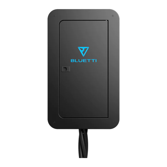
Summary of Contents for Bluetti Sub Panel
- Page 1 Please read this manual before use and follow its guidance. Keep this manual for future reference.
- Page 2 User Manual Please read this manual before use and follow its guidance. Keep this manual for future reference.
-
Page 3: Table Of Contents
1.3 In The Box …………………………………….……………………………………………………………………………02 1.4 Quality Inspection……………………………………………………………………………….….………………02 1.5 Sign…………………………………………………………………………………………………………….…………………02 1.6 Safety……………………………………………………………………………………………………………………………02 2. Installation…………………………………………………………………………………………………………..………03 2.1 Preparation……………………………………………………………………………………………………..…………03 2.2 Installation…………………………………………………………………………………………………...……………03 2.3 Sub Panel Wiring...……………………………………..…………………………………………….……………05 3. Connection……………………………………………………………………………………………..…………………07 3.1 Single Connection ……………………………………......………………………...…………07 3.1.1 Single EP500……………………………………………………………………....…………………………07 3.1.2 Single EP500 Pro………………………………………………………………..………………………………08 3.1.3 Single AC300…………………………………………………………………….....…………………………09 3.2 Split Phase Connection System………………………………..………………………………………10 3.2.1 Dual EP500………………………………………………………………………....………………………10... -
Page 4: Introduction
RV, or remote locations where utility power is unavailable or in place of a utility due to a power outage. The Sub Panel is compatible with installations in the United States, Canada, Mexico, Japan, and other countries. -
Page 5: In The Box
1.6 Safety User manual contains safety information to make you aware of hazards and risks associated with Sub Panel and how to avoid them, and instruc- tion about installation, operation, maintenance. It is essential to read and understand these instructions thoroughly before attempting to start or operate this equipment. -
Page 6: Installation
The cable for connecting AC300 or EP500 series with Sub Panel contained in the package, please follow the instruction. 1) Take out the screw from the front cover of Sub Panel and remove it as Figure 2.2. - 03 -... - Page 7 Figure 2.2 Remove Front Cover 2) Drill into the wall according to the size of Sub Panel. Type A - Mounting: 4PCS Expansion Screw for concrete wall, tapping screw for wooden. 226mm Figure 2.2.1 Drill & Mount Type B - Hanging: 2PCS Expansion Screw for concrete wall, tapping screw for wooden.
-
Page 8: Sub Panel Wiring
3) Mount the Sub Panel. Figure 2.3.1 Drill & Mount Figure 2.3.2 Drill & Mount Mount the Sub Panel on wall from the pre-bored holes. 2.3 Sub Panel Wiring Please follow the next steps after you have properly mounted the Sub Panel. - Page 9 2.3.1 Wiring to Grid 1) Determine the length of the connecting wire according to the distance from the Sub Panel to the Main Panel. 2) Connect the Line Wires, Neutral Wires to the circuit breaker`s wiring bar on Sub Panel.
-
Page 10: Connection
3. Connection Sub Panel supported Single or Dual BLUETTI Power Station connection. Compatible Model: EP500/Pro, AC300. Please contact to the dealer whether you order the Sub Panel Version is compatible with your power station. DANGER: Read the user manual before installation. -
Page 11: Single Ep500
Figure 3.1 Input Plug Figure 3.2 Off-grid Output Plug (For EP500) (For EP500) Connection of single EP500 with Sub Panel Cable involved in the package of Sub Panel to connect with EP500 solar power station. CRITICAL LOAD CRITICAL LOAD NON-CRITICAL LOAD... -
Page 12: Single Ep500 Pro
3.1.2 Single EP500 Pro Cable involved in the package of Sub Panel to connect with EP500Pro solar power station. Figure 3.5 Input Plug Figure 3.6 Off-grid Output Plug (For EP500Pro) (For EP500Pro) Connection of single EP500Pro with Sub Panel CRITICAL LOAD... -
Page 13: Single Ac300
3.1.3 Single AC300 Cable involved in the package of Sub Panel to connect with AC300 solar power station. Figure 3.9 Input Plug Figure 3.10 Off-grid Output Plug (For AC300) (For AC300) Connection of single AC300 with Sub Panel CRITICAL LOAD... -
Page 14: Split Phase Connection System
The load capacity should exceed the Grand Max Power of Input of Power Station. 3.2.1 Dual EP500 Cable involved in the package of Sub Panel to connect with Dual EP500 solar power station. Figure 3.13 Input Plug Figure 3.14 Off-grid Output Plug... -
Page 15: Dual Ep500 Pro
3.2.2 Dual EP500 Pro Cable involved in the package of Sub Panel to connect with Dual EP500- Pro solar power station. Figure 3.17 Input Plug Figure 3.18 Off-grid Output Plug (For EP500Pro) (For EP500Pro) CRITICAL LOAD CRITICAL LOAD NON-CRITICAL LOAD... -
Page 16: Dual Ac300
3.2.3 Dual AC300 Cable involved in the package of Sub Panel to connect with Dual AC300 solar power station. Figure 3.21 Input Plug Figure 3.22 Off-grid Output Plug (For AC300) (For AC300) CRITICAL LOAD CRITICAL LOAD NON-CRITICAL LOAD POWER GRID... -
Page 17: Operation
Sub Panel supports manual bypass conversion function for maintenance, When you want to remove the EP500/Pro, AC300 Power Station from the Sub Panel, please tweak the rotary switch on Sub Panel to “2” (Figure 4.3) to maintenance then disconnect the connecting cable on Power Station,- household load will be powered directly by the utility power. - Page 18 floating neutral to bonded neutral. If you want to convert the Sub Panel to bonded neutral, please connect the Sub Panel with Main Panel, or follow the instruction to connect the Neutral bus-bar to PE. Socket 1...
-
Page 19: Specifications
Clean exterior cover of Sub Panel regularly. Regularly check whether the wires of each part integrated in Sub Panel, damaged wires should be replaced immediately. Please contact the dealer if the issues are not able to solve, detailed record of the problems will help. - Page 20 fications due to the exterior material and hardware improvement. Version A 2.1 Version. Date: July 2021 Company: POWEROAK GmbH Address: Lindwurmstr. 114, 80337 München Germany Mail: logi@bluetti.de Company: POWEROAK ENERGY UK CO.,LTD Address: Suite 108 Chase Business Center 39-41 Chase Side London United Kingdom N14 5BP Mail:poweroak.eu@bluetti.com P/N:17.0303.0391-00A0...


Need help?
Do you have a question about the Sub Panel and is the answer not in the manual?
Questions and answers