Pioneer VSX-LX52 Service Manual
Hide thumbs
Also See for VSX-LX52:
- Operating instructions manual (116 pages) ,
- Operating instructions manual (114 pages)
Table of Contents
Advertisement
ORDER NO.
RRV3933
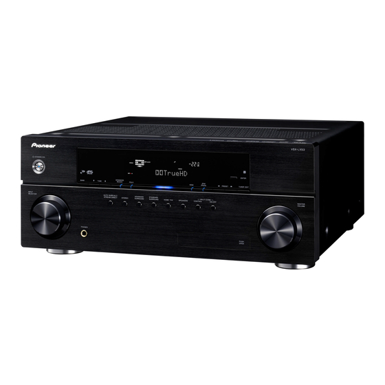
VSX-LX52
AUDIO/VIDEO MULTI-CHANNEL RECEIVER
VSX-LX52
THIS MANUAL IS APPLICABLE TO THE FOLLOWING MODEL(S) AND TYPE(S).
Model
Type
Power Requirement
Remarks
VSX-LX52
SYXJ5
AC 220 V to 230 V
For details, refer to "Important Check Points for good servicing".
PIONEER CORPORATION
4-1, Meguro 1-chome, Meguro-ku, Tokyo 153-8654, Japan
PIONEER ELECTRONICS (USA) INC. P.O. Box 1760, Long Beach, CA 90801-1760, U.S.A.
PIONEER EUROPE NV Haven 1087, Keetberglaan 1, 9120 Melsele, Belgium
PIONEER ELECTRONICS ASIACENTRE PTE. LTD. 253 Alexandra Road, #04-01, Singapore 159936
PIONEER CORPORATION
2009
T-ZZV MAY
2009 Printed in Japan
Advertisement
Table of Contents

Related Manuals for Pioneer VSX-LX52


Summary of Contents for Pioneer VSX-LX52
- Page 1 PIONEER CORPORATION 4-1, Meguro 1-chome, Meguro-ku, Tokyo 153-8654, Japan PIONEER ELECTRONICS (USA) INC. P.O. Box 1760, Long Beach, CA 90801-1760, U.S.A. PIONEER EUROPE NV Haven 1087, Keetberglaan 1, 9120 Melsele, Belgium PIONEER ELECTRONICS ASIACENTRE PTE. LTD. 253 Alexandra Road, #04-01, Singapore 159936...
-
Page 2: Safety Information
PIONEER Service Manual. A subscription to, or additional copies of, Also test with plug reversed Earth PIONEER Service Manual may be obtained at a nominal (Using AC adapter ground charge from PIONEER. plug as required) - Page 3 To protect products from damages or failures during transit, the shipping mode should be set or the shipping screws should be installed before shipment. Please be sure to follow this method especially if it is specified in this manual. VSX-LX52...
-
Page 4: Table Of Contents
10.25 POWER SW, ENCODER, HEAD PHONE and DIODE ASSYS ................124 10.26 BRIDGE 1 and 2 ASSYS ............................125 10.27 POSI 1-3, BIND L FRONT and BACK, BIND R FRONT and BACK ASSYS............126 10.28 BINDER and DISP-FFC GUARD ASSYS .......................127 11. PCB CONNECTION DIAGRAM ............................128 11.1 AUDIO ASSY ................................128 VSX-LX52... - Page 5 11.11 POWER SW, ENCODER, HEAD PHONE, DIODE, BRIDGE 1 and 2 ASSYS............158 11.12 POSI 1-3, BIND L FRONT and BACK and BIND R FRONT ASSYS ..............160 11.13 BIND R BACK, BINDER and DISP-FFC GUARD ASSYS ..................162 12. PCB PARTS LIST................................163 VSX-LX52...
-
Page 6: Service Precautions
DIGITAL MAIN AWX9420 ASSY IC1501 HDMI Receiver SII9233ACTU IC with heat-pad 1.3 CAUTION • Discharging Please refer to page 52, “Preparations Before Perfoming Diagnosis of the POWER AMP Assy”. • Ground Points Please refer to page 53, “Ground Points”. VSX-LX52... -
Page 7: Specifications
Dimensions . . . 420 (W) mm x 173 (H) mm x 433 (D) mm Weight (without package)....13.5 kg VSX-LX52... -
Page 8: Panel Facilities
Use for connection to compatible HDMI device (Video Receives the signals from the remote control. camera, etc.). 8 MASTER VOLUME dial 9 PHONES jack Use to connect headphones. When the headphones are connected, there is no sound output from the speakers. VSX-LX52... - Page 9 ADV.SURROUND – Lights when one of the Advanced Lights to indicate the receiver’s remote control mode Surround modes has been selected. setting. (Not displayed when set to 1.) STEREO – Lights when stereo listening is switched on. STANDARD – Lights when one of the Standard VSX-LX52...
- Page 10 Multiple inputs and two outputs for high-quality audio/ 13 Control input/output video connection to compatible HDMI devices. Use to connect other Pioneer components so that you can control all your equipment from a single IR remote 2 Coaxial digital audio inputs (x2) sensor.
- Page 11 Use INPUT SELECT to select the input function. 3 Number buttons and other receiver/component controls Use the number buttons to directly select a radio frequency or the tracks on a CD, DVD, etc. ENTER can be used to enter commands for TV or DTV. VSX-LX52...
- Page 12 Press to turn on/off other components connected to the receiver. 14 MASTER VOLUME +/– Use to set the listening volume. 15 MUTE Mutes the sound or restores the sound if it has been muted (adjusting the volume also restores the sound). VSX-LX52...
-
Page 13: Basic Items For Service
Item to be checked regarding video Item to be checked regarding audio Block noise Distortion Horizontal noise Noise Flicker Volume too low Disturbed image (video jumpiness) Volume too high Too dark Volume fluctuating Too bright Sound interrupted Mottled color VSX-LX52... -
Page 14: Pcb Locations
POSI 1 ASSY POSI 3 ASSY POSI 2 ASSY BIND R FRONT BIND L FRONT ASSY ASSY BINDER ASSY XM REGULATOR ASSY UNREG ASSY REGULATOR ASSY HEADPHONE FRONT MIC&VIDEO FRONT HDMI&USB ASSY ASSY ASSY ENCODER ASSY DISPLAY ASSY POWER SW ASSY VSX-LX52... -
Page 15: Jigs List
AWX9380 2..COMPONENT ASSY AWX9390 1..FM/AM TUNER UNIT AXX7248 2..COMPOSITE&S ASSY AWX9392 3.3 JIGS LIST [1] Jigs list Name Jig No. Remarks Diagnosis 15P board to board extension jig GGD1484 cable Diagnosis 17P board to board extension jig GGD1648 cable VSX-LX52... -
Page 16: Block Diagram
11/11 (AWX9365) CN7751 DIGITAL MAIN ASSY CN8503 (AWX9420) 1/2- COMPOSITE & S ASSY (AWX9392) CN8601 CN8502 CN1250 CN1251 CN1252 CN1253 CN1254 CN8009 CN8008 CN8005 CN8004 CN8003 CN8002 CN8001 DISP-FFC BINDER GUARD ASSY ASSY (AWX9539) (AWX9373) ADX7688- FRONTV GNDF 2/430 VSX-LX52... - Page 17 (*;1.00mm FFC CONNECTOR) D20PYY0460E 1.25mm FFC CONNECTOR(I) HPDET (*;1.00mm FFC CONNECTOR) CN4701 (*;0.50mm FFC CONNECTOR) 4/600 GNDHP 1.25mm FFC (*;1.00mm FFC) *2mm (*;0.50mm FFC CONNECTOR) 2.0mm CABLE COMPONENT ASSY 2.0mm FLAT CABLE 1/2- DIODE ASSY (AWX9390) ANOTHER CONNECTOR (AWX9406) PH SHIELD VSX-LX52...
-
Page 18: Block Diagram For Digital Audio Block
From HDMI Block IC521 IC521 IC363 AK4388ET AK4388ET 7WH126(2/2) Buffer IC1563 7WH157 IC231 74VHC157 HDMI AUDIO SW IC1566 IC241 VHC541 74VHC125 Channel Assigment Difference IC301 Pin No. SACD Signal OTHER Signal Data(C) Data(LFE) Data(FL,FR) Data(FL) Data(FR) Data(SL,SR) Data(SL) Data(C,LFE) Data(SBL,SBR) Data(SR) VSX-LX52... - Page 19 IC452 #5,7,9,11,13,15,17,19 7WH126(2/2) 7SZ08 74LCX541 74LCX541 EXTAL HCKT_3 HCKT SCKR, FSR SCKT_3, FST_3, SCKT, FST SDI0_1 SDO2_2 to SDO5_2 IC301 DSPA56720AG SDI1_1 SDI3_1, SDI0 SDI1 R Signal SDRAM Flash ROM IC251 L,FR) IC261 64Mbit L,SR) AYW7305 (4bank*1M*16bit) ,LFE) BL,SBR) VSX-LX52...
-
Page 20: Block Diagram For Analog Audio Block
4.3 BLOCK DIAGRAM FOR ANALOG AUDIO BLOCK VSX-LX52... -
Page 21: Block Diagram For Digital Video Block
4.4 BLOCK DIAGRAM FOR DIGITAL VIDEO BLOCK VSX-LX52... -
Page 22: Block Diagram For Analog Video Block (1/2)
4.5 BLOCK DIAGRAM FOR ANALOG VIDEO BLOCK (1/2) COMPONENT ASSY VSX-LX52... - Page 23 COMPOSITE & S ASSY TC4094BFN CN8502 * Refer to 4.6 BLOCK DIAGRAM FOR ANALOG VIDEO BLOCK (2/2) VSX-LX52...
-
Page 24: Block Diagram For Analog Video Block (2/2)
4.6 BLOCK DIAGRAM FOR ANALOG VIDEO BLOCK (2/2) * Refer to 4.5 BLOCK DIAGRAM FOR ANALOG VIDEO BLOCK (1/2) CN8008 COMPOSITE & S ASSY S-VIDEO BLOCK VSX-LX52... -
Page 25: Block Diagram For U-Com Block
The User Memory data is stored in IC1050(AYW7307) of EMMA Flash ROM and IC3001(PDC188B8) of Event ucom. The setting of the protection history and zone is stored in EVENT ucom and other setting data of user data is stored in EMMA Flash ROM. VSX-LX52... -
Page 26: Block Diagram For Power Block
4.8 BLOCK DIAGRAM FOR POWER BLOCK VSX-LX52... - Page 27 VSX-LX52...
-
Page 28: Diagnosis
(to chassis) Is the Is the Check the C121, C114, voltage of 3.3 V Check the C606, C656, C706 voltage of 5 V C509 and C459. output? input? and C756. Replace IC581. Replace Q551 (side B). To Step 3 VSX-LX52... - Page 29 Check that it changes in the Playback and Pause modes of the HDMI. From HDMI block IC101 (Pin 5) Check the HDMI block, and the parts observe the digital signal and patterns in the path. (0 V ⇔ 3.3 V) VSX-LX52...
- Page 30 Check the HDMI block, and the parts and patterns in the path. Step 5-3 IC301 (Pin 89) (or R327) DSP0MCLK Is there a data input? (0 V ⇔ 3.3 V) IC301 (Pin 134) DSP1MCLK Is there a data input? (0 V ⇔ 3.3 V) VSX-LX52...
- Page 31 Digital output of each CH when inputting the digital signal (-∞ dB (no audio)). IC301 (Pin 123) (or R348) Center/LFE data Is the output Replace IC301. 0 V fixing? IC301 (Pin 124) (or R348) Surround L/R data Is the output Replace IC301. 0 V fixing? VSX-LX52...
- Page 32 Is the output Replace IC751. 2.5 V fixing? CN501 (Pin 19) Surround Back L out CN501 (Pin 19) Surround Back L out Is there Replace IC751. Is the output a data output? Replace IC751. 2.5 V fixing? VSX-LX52...
- Page 33 Check Points of the DIGITAL MAIN Assy 21 1 5: V+1_DSPF 8: V+5_DACA 3: V+3R3_D 2: V+5_DDD1 6: V+5_DAC 7: V+5_DACD SIDE A DIGITAL MAIN ASSY VSX-LX52...
- Page 34 18 19 DIGITAL MAIN ASSY SIDE A VSX-LX52...
- Page 35 I2S (3 lines) Compression DVD-V 48 Compression *.WAV 44 dts-CD Indistinguishable DVD-V LPCM Multi Multi Multi DVD-A Multi Multi Multi SACD (DSD) Multi (DSD) dts HD Master Audio dts HD High Resolution Audio dts HD LBR Dolby TrueHD Dolby Digital Plus VSX-LX52...
- Page 36 Check IC1930 and its peripheral circuits. L1932 V+1R8_HHH Is the Check Q1931 and its periphery. voltage of around (Pin 1: around 5.5 V Square wave 1.8 V output Pins 7,8: around 16.5 V) Check IC1930 and its peripheral circuits. VSX-LX52...
- Page 37 JA1602-JA1604 the path. (around 3.3 V) TMDS signal (Pins 1,3,4,6,7,9,10,12) R1509 Is there Check the soldering of JA1602- 0.5Vp-p in CLK JA1604. and DATA? Is the Check the soldering and parts of voltage "H" the path. (around 3.3 V) VSX-LX52...
- Page 38 TMDS signal (Pins 1,3,4,6,7,9,10,12) Is there Check IC1601 and its peripheral 0.5Vp-p in CLK Is there circuits. Check the power and soldering of and DATA? 0.5Vp-p in CLK IC1501,IC1800 and IC9000, and DATA? and its peripheral circuits. To Step 4-3 VSX-LX52...
- Page 39 0.5Vp-p in CLK IC1601 and CN1601. and DATA? Check IC1501 and its peripheral Whole circuits. diagram IC1601 (Pins 25,26, TMDS signal 28,29,31,32,34,35) Is there Check IC1601 and its peripheral 0.5Vp-p in CLK circuits. and DATA? To Step 5-2 To Step 5 VSX-LX52...
- Page 40 64),R1706 (side B) VOCLK Are the Check IC1701 and its peripheral signals output? To Step 6 circuits. IC1805 (Pins 3-9), Q16-23 IC1806 (Pin 4) (side B) VICLK Are the Check IC1805, IC1806 and its signals output? peripheral circuits. To Step 7 VSX-LX52...
- Page 41 A_VCROUT Replace Q1202, Q1203, Q1204 Are there and its peripheral parts. signals? CN1254 (Pin 7) A_VCYOUT CN1254 (Pin 9) A_VCBOUT CN1254 (Pin 11) A_VCROUT Check the soldering and Are there connection of the CN1254. signals? Diagnose the COMPONENT Assy. VSX-LX52...
- Page 42 Are there connection of the CN1252. signals? Diagnose the COMPONENT Assy. To Step 10 Step 11: GUI/JPEG (USB) Composite/S/Component OUT Diagnose the IC800 (through hole) of Composite/S/ Component OUT and later. Step 12: GUI/JPEG (USB) HDMI OUT Go to VSX-LX52...
- Page 43 Check Points of the DIGITAL MAIN Assy IC9000 SIDE A Whole DIGITAL MAIN ASSY OUT2 OUT1 diagram R1509 IC1809 IC1807 A: V+13_UN B: V+5_HDD C: V+5_HD VSX-LX52...
- Page 44 The points to be checked for other connectors are the same. IN 3 IN 2 IN 1 IN BD SIDE A DIGITAL MAIN ASSY R879 Q1200 R887 R885 R1203 Q1201 R873 R1209 Q1204 R1214 Q1202 IC1800 R884 R874 R886 Q1203 R872 R875 R1270 IC800 VSX-LX52...
-
Page 45: Circuit Description
+DC detection: Q5741/Q5743 base is "H". –> Collector of Q5741, Q5742, Q5743 and Q5744 are "L". C ch L ch SL ch SBL ch -DC detection: Q5742/Q5744 emitter is minus to the base. –> Collector of Q5741, Q5742, Q5743 and Q5744 are "L". VSX-LX52... - Page 46 OL det: 0.6V OL DETECTOR Q5041 D5043 R5043 R5732 Q5731 GNDU OUTPUT L ch GNDU GAMP Q5002 R5044 DIGITAL MAIN ASSY D5143 SL ch D5243 SBL ch D5343 R ch D5443 SR ch D5543 SBR ch D5143 C ch VSX-LX52...
- Page 47 Q5784 1SS352 V+5_UST LTA124EUB 1SS352 Q5783 R5784 LTA124EUB Q5785 LTC124EUB Q5782 GAMP LTC124EUB UDZS7R5(B) GNDU D5782 GNDU Q5781 LTC124EUB GNDU CN5805 CN8014 COMPONENT ASSY CN8005 CN1250 DIGITAL MAIN ASSY CN1401 DISPLAY ASSY CN3001 V+5_ST UCOM IC3001 C3016 0.047u/50 GNDU VSX-LX52...
- Page 48 [3] Error Indications When an Abnormality in The Amplifier System Is Detected [Purpose] Errors upon detection of abnormalities in the amp system are indicated. [Error Indications] VSX-LX52...
- Page 49 VSX-LX52...
-
Page 50: Service Mode
H O L D R E S E T times error is detected. R E S E T C L E A R ? [ ↑ ] [ENTER] [↓] R E S E T R E S E T ↓ Continued VSX-LX52... - Page 51 6 0 0 m s ↓ Change cyclically Change cyclically [Description] CEC TEST : The function for making the HDMI output terminal to output 1kHz square wave. If the square wave is output, the CEC line is considered to be normal. VSX-LX52...
-
Page 52: C 7. Disassembly
Note: For discharging, use a load of 100 Ω , 3 W or more, to protect the IC protectors. Do NOT discharge instantly by short-circuiting. (3) Check that the voltage between the electrodes of each C5721 and C5722 is 1 V or less. DIODE Assy pin 1 + D4701 pin 4 ≠ D4701 C5722 C5721 POWER AMP Assy J270 J273 P5001 P5002 VSX-LX52... - Page 53 Before turning the unit ON, be sure to ground the marked points with the chassis. Or, you may short-circuit the ground points on the solder surface, using pieces of wire. Ground any one of these points. Ground any one of these points. Ground any one of these points. Screws for Rear Panel BBZ30P080FTB BMZ30P040FTB BBT30P100FCC ABA7078 VSX-LX52...
- Page 54 (1) Remove the five screws. (ABA1193) (2) Remove the nine screws. (BBZ30P080FCC) HEADPHONE FRONT MIC&VIDEO FRONT HDMI&USB Assy Assy Assy (3) Disconnect the one connector. (4) Release the jumper wires, as required. CN4052 REGULATOR Assy BIND L FRONT BIND L BACK Assy Assy VSX-LX52...
- Page 55 (6) Remove the front panel section. Front panel section (7) Remove only the right part hook of AEC7626 HEADPHONE FRONT MIC&VIDEO FRONT HDMI&USB at this state, and then remove the FFC. Assy Assy Assy POWER SW Assy ENCODER Assy DISPLAY Assy VSX-LX52...
- Page 56 (2) Remove the two screws. (BBZ30P080FCC) Heatsink [2-3] POWER AMP and DIODE Assemblies POWER AMP Assy COMPONENT Assy (1) Remove the two rivets. (2) Remove the one screw. (BBZ30P080FCC) (3) Remove the two screws. (BBZ30P080FCC) (4) Remove the two screws. (BBZ30P080FCC) DIODE Assy VSX-LX52...
- Page 57 (2) Arrange the unit as shown in the photo below. Caution: DIODE Assy Fix the DIODE Assy to rear panel with tape not to touch other part. Rear panel (3) Connect the rear panel to the chassis ground. POWER AMP Assy Chassis VSX-LX52...
- Page 58 (2) Remove the four screws. (BBT30P100FCC) (3) Remove the six screws. (BMZ30P040FTB) (4) Remove the two hex head screws. (ABA7078) (5) Remove the 30 screws. (BBZ30P080FTB) ×4 ×2 1 1 1 1 [3-3] Diagnosis (1) Arrange the unit as shown in the photo below. VSX-LX52...
- Page 59 (5) Connect the ground points to the chassis ground. (See “Ground points.”) Notes: When diagnosing the AUDIO Assy, the set is able to operate even if removing the COMPOSITE Assy. POWER AMP Assy 17P board to board cable (GGD1648) 15P board to board cable (GGD1484) VSX-LX52...
-
Page 60: Each Setting And Adjustment
2. The updating process is as follows. The FL display and procedure of the updating process is same for both mode. For UPDATE PANEL 2 Mode, after completing the update, it is necessary to disconnect then reconnect the AC cord of the unit. VSX-LX52... - Page 61 Update Confirmation U P D A T E Y E S [ENTER] File searching P L E A S E W A I T UPDATE FILE searching completed Updating process U P D A T E DSP UPDATE completed VSX-LX52...
- Page 62 Following the procedures described in "Version Indication" in this section, check that the version has been changed to a new one. [Procedure for UPDATE PANEL 2 Mode] After completing the UPDATE PANEL 2 Mode update and confirming the version, it is necessary to disconnect then reconnect the AC cord of the unit. VSX-LX52...
- Page 63 VSX-LX52...
-
Page 64: Exploded Views And Parts List
Screws adjacent to b mark on product are used for disassembly. For the applying amount of lubricants or glue, follow the instructions in this manual. (In the case of no amount instructions, apply as you think it appropriate.) 9.1 PACKING SECTION VSX-LX52... - Page 65 NSP 17 Warranty Card EU ARY7128 18 Label (WEEE) ARW7322 NSP 19 Polyetylene Bag (A4 x 2) AHG7132 20 Protection Sheet LX AEH7030 21 Packing Sheet RHC1023 22 Front Pad V5SEL AHA7472 23 Rear Pad V5SEL AHA7473 24 Packing Case 52SVY AHD8656 VSX-LX52...
-
Page 66: Exterior Section
CN3001 FRONT FRONT MIC&VIDEO MIC&VIDEO CN3472 CN3471 AUDIO FRONT HDMI&USB CN2206 CN7502 HEADPHONE CN3451 PRIMARY CN3708 Accessory of Panel base Accessory of Panel base DISPLAY JP3001 AUDIO JP2205 DIGITAL MAIN CN1901 DIGITAL MAIN CN1900 Refer to “9.4 FRONT SECTION”. VSX-LX52... - Page 67 40 Bonnet B V5SEL (BOX) AZN8034 41 License Label V6S H ARW7388 42 • • • • • 43 • • • • • 44 Screw 3 x 10 (FE) ABA1193 45 Hex head Screw 2.85 X 7 (BS) ABA7078 VSX-LX52...
-
Page 68: Rear Section
Panel base POSI 2 CN7002 POSI 3 CN7003 REGULATOR XM REGULATOR CN4002 JP4252 DISPLAY CN3001 POSI 1 CN7001 Power transformer REGULATOR CN4051 PRESTAGE CN6603 PRESTAGE JP6901 REGULATOR CN4102 FRONT MIC&VIDEO CN3471 FRONT MIC&VIDEO CN3472 POWER AMP CN5805 POWER AMP CN5804 VSX-LX52... - Page 69 PEB1306 20 Cushion Circle 14B AED7081 21 Nylon Rivet AEC7406 NSP 22 Binder (BK-1) ZCA-BK1 23 • • • • • 24 • • • • • 25 Screw AMZ26P040FTC 26 Screw BMZ30P040FTB 27 Screw BBZ30P080FCC 28 Screw BBZ30P080FTB VSX-LX52...
-
Page 70: Front Section
9.4 FRONT SECTION POWER AMP JH5801 REGULATOR CN4052 DIGITAL MAIN CN1401 Accessory of Panel base DIGITAL MAIN CN1259 DIGITAL MAIN CN1601 COMPONENT CN8017 AUDIO CN2204 VSX-LX52... - Page 71 23 CTR BTN Left Assy XXG3416 24 Window LX52 Assy AXG7413 25 ENTER BTN Spacer V6 AAK8479 26 Window LX52 AAK8483 27 Pioneer Badge VAM1158 28 ENTER Button V6S XAD3271 29 F. HDMI Shield ANK7147 30 VOL Ring 60 ABH7249...
-
Page 72: Schematic Diagram
47u/25 R2164 C2166 SW_IN 47u/25 C2101 R2173 C2175 SL_IN 0.01u/50 47u/25 mark found on some component parts should be replaced with C2102 A_A_ANA_CIN A_A_ANA_SWIN same parts (safety regulation authorized) of identical designation. GNDCH SR_IN A_A_ANA_LSIN R2174 C2176 A_A_ANA_RSIN 47u/25 VSX-LX52... - Page 73 R2887 47u/25 GNDA 100p/50 47u/25 470p/50 Q2881 Q2881 470p/50 IMX25 IMX25 100p/50 SBMUTE R2888 R2884 R2890 C2888 AMUTE 47u/25 C2871 JH2001 JH2002 JH2003 R2882 R2886 0.01u/50 VEF1040-A VEF1040-A VEF1040-A C2872 Q2882 Q2882 0.1u/16 IMX25 IMX25 GNDA GNDCH GNDA CN6603 VSX-LX52...
-
Page 74: Composite (1/2) And V-Bridge Assys
V-5_V to S-VIDEO OSDDT R8518 X8501 L8501 OSDCK R8519 R8520 OSDCS LSA1 R8563 V-5_V R8562 GNDU C8560 ASS7080-A C8558 C8561 C8559 GNDV GNDOS1 GNDOS2 to S-VIDEO from S- C8551 C8541 0.01u/50 R8542 R8539 GNDV GNDU GNDF2 CN8601 XKP3076-A CN8009 VSX-LX52... - Page 75 R8555 CN7751 100k XKP3075-A CN8503 Q8502 LSA1576UB(QR) V-BRIDGE ASSY Substitute 2SA1576A(QR) 2SA1602A(EF) R8563 (AWX9495) V-5_V D8509 C8560 RR264M-400 V-5.6_V V-5_V C8561 *CN7752 TO D-TERM ASSY GNDV XKP3065-A to S-VIDEO from S-VIDEO GNDV GNDVP C8556 C8557 GNDV CN8502 XKP3080-A CN8008 VSX-LX52...
-
Page 76: Composite Assy (2/2)
VIDEOIN_Y TVIN_Y V+5_V IC8601 TVIN_Y V-5_V TC74HC4051AFT B1/2 DVDIN_C DVDIN_C DVRIN_C DVRIN_C VIDEOIN_C VIDEOIN_C TVIN_C V+5_V IC8602 TVIN_C IC8603 Y-CO X-CO Z-COM V-5_V TC74HC4051AFT V-5_V TC74HC4053 Substitute Substitute V+5_V 2SA1576A(QR) 2SA1576A(QR) 2SA1602A(EF) 2SA1602A(EF) R8608 R8609 R8617 R8618 V-5_V B1/2 VSX-LX52... - Page 77 Rated Power: 1/16W unless otherwise noted. Toleranee: (J) ±5% unless otherwise noted. 2. CAPACITORS No marked Capacitors are CEAT or CKSRYB. Unit: p-pF or u-uF unless otherwise noted. Ratings: Capacity(F)/Voltage(V) unless otherwise noted. 3. NM: No Mount : Video Signal Route VSX-LX52...
-
Page 78: Component Assy (1/2)
Q8201, 8202, 8211, 8212, 8221, 8222, 8241, 8242 C8215 Substitute R8214 10u/50 A_CBINDVC1 2SA1576A(QR) 2SA1602A(EF) GNDV V-5_V V+5_V V+5_V R8232 R8226 A_CRINDVC C8225 R8224 10u/50 A_CRINDVC1 (CY) GNDV V-5_V R8231 GNDV V+5_V A_CV/YINDVC R8246 C8245 R8244 10u/50 A_CYINDVC1 GNDV V-5_V VSX-LX52... - Page 79 Unit: p-pF or u-uF unless otherwise noted. C8102 Ratings: Capacity(F)/Voltage(V) unless otherwise noted. 3. NM: No Mount GNDU3 (CY) : Video Signal Route (CY),(Y) EXSTANLG_5 (CB) : Video Signal Route (CB) OSDSO_5 OSDSCK_5 (CR) : Video Signal Route (CR) R8106 C53ABC CSW1 R8105 GNDU3 VSX-LX52...
-
Page 80: Component Assy (2/2)
: Video Signal Route (Y) (CB) : Video Signal Route (CB) (CR) : Video Signal Route (CR) Substitute 2SC4081(QR) 2SC4154(EFG) V+5R6_V V+5_V V+3_V D8385 D8382 RR264M-400 C8391 R8391 R8387 GNDV GNDVP GNDV C8411 D8402 D8405 RR264M-400 V-5R6_V V-5_V V-3_V Substitute 2SA1576A(QR) 2SA1602A(EF) VSX-LX52... - Page 81 GNDU3 R8455 V+5R6_V GNDF2 GNDF C8455 IC8451 0.1u/16 NJM2505AF D8452 C8451 0.01u/50 R8452 C8452 C8456 1000p/50 CN8017 10u/6.3 AKM1273-A R8453 C8453 VGND Vout GNDF 10u/6.3 D8451 DAN217U FRONTV V+5R6_V GNDF2 C8454 BOTTOM R8454 CN3472 VEF1040-A JH8002 JH8001 CN5804 CN5805 VSX-LX52...
-
Page 82: Digital Main Assy (1/11)
V+1_EM V+1_EM_PLL IC807 L801 DTL1106-A TP811 GNDD V+3R3_EM_D L810 QTL1013-A GNDD C928 IC803 0.1u/10 V+3R3_EM_D TC7WHU04FU C929 *R869 1000p/50 *R870 R965 to USB R966 CLK27ABT C926 GNDD 10p/50 5/11 R888 X801 ASS7092-A 27MHz C927 R889 10p/50 GNDD GNDD 1/11 VSX-LX52... - Page 83 C1019 TADRS2 TADRS5 1u/6.3 R974 R1045 TADRS3 TADRS4 GNDD C1029 C1027 GNDD GNDS DCS0B VDD3 VSS1 0.1u/16 1000p/50 GNDD DRAS TRAS V+3R3_EM_D *R869 DCAS TCAS *R870 GNDD R1046 R1036 TCLKO DCLKO DCLKNO TCLKNO R1047 R1037 to DDR SDRAM 1/11 VSX-LX52...
- Page 84 1/11 VSX-LX52...
- Page 85 1/11 VSX-LX52...
- Page 86 1/11 VSX-LX52...
- Page 87 1/11 VSX-LX52...
-
Page 88: Digital Main Assy (2/11)
R1181 R1178 0.82u 1.2u mark found on some component parts should be replaced with ATL7033-A ATL7035-A C-Cr same parts (safety regulation authorized) of identical designation. GNDD (VCR) R1184 A_VCRIN Q1156 NM: No Mount 2SA1576A(QR) GNDD GNDD GNDD 2/11 GNDD VSX-LX52... - Page 89 SG_B GNDD GNDD V+1R8_HHH V+1_EM 4/11 GNDD TP1104 D1104 IC1104 EMPOW R1106 CONT 3/11 Q1157 2SC4081(QR) R1181 VOUT MM1701WH GNDD (VCR) C1182 A_VCRIN_EM Analog Video In (1608) GNDD SG_C GNDD 1/11 Power Line for EMMA GNDD 4/11 2/11 GNDD VSX-LX52...
-
Page 90: Digital Main Assy (3/11)
C1342 0.1u/10 0.1u/10 NM: No Mount IC1304 IC1305 BU4094BCFV BU4094BCFV R1342 DATA DATA R1344 CLOCK CLOCK R1343 R1359 100k R1357 R1356 R1326 100k 100k R1360 R1363 100k 100k GNDD R1358 R1361 (EXP_7) (EXP_8) 100k 100k R1362 100k GNDD 3/11 VSX-LX52... - Page 91 AC INLET Side (NPN) CKF1084-A POS3 R1460 GNDU GNDU CN7003 GNDCH4 GNDCH3 GNDCH2 100k R1363 *Q1409 GNDD (PNP) GNDD RN4903 GNDD GNDD *CN1404 GNDD AKM1288-A AC INLET Side R1459 *Q1409 (NPN) POS2 CN7002 GNDU D1403 GNDU C1420 3/11 C1421 GNDD VSX-LX52...
-
Page 92: Digital Main Assy (4/11)
Data1- Data1 Shield R4X1+ X1501 Data1+ ASS7092-A R4X2- 27MHz Data2- Data2 Shield R4X2+ GNDD GNDD Data2+ mark found on some component parts should be replaced with GNDD same parts (safety regulation authorized) of identical designation. NM: No Mount 4/11 VSX-LX52... - Page 93 R1752 V+3R3_HHH IC1702 TC7WHU04FU L1704 QTL1013-A 5/11 CEC_IO_1 (VCY) : Video Signal Route (VCY) (VSC) R1741 : Video Signal Route (VSC) GNDD (VCB) : Video Signal Route (VCB) X1701 (VCR) 4/11 : Video Signal Route (VCR) ASS7096-A 28.63636MHz GNDD VSX-LX52...
-
Page 94: Digital Main Assy (5/11)
0.1u/10 C1832 470p/50 VOD8 R1879 VOD9 VOD10 VOD11 VOD12 VOD13 GNDD VOD14 VOD15 R1880 IC1803 TC74LCX541FTS1 GNDD mark found on some component parts should be replaced with same parts (safety regulation authorized) of identical designation. NM: No Mount 5/11 VSX-LX52... - Page 95 CTF1386-A GNDD *R9118 XHDTX2RST FAULT GNDD GNDD V+3R3_HHH R9021 XBAOUT C9052 R9023 68 R9027 0 R9025 0.1u/10 IC9003 R9029 R9026 0 TC7SH08FUS1 R9022 68 R9028 R9024 68 V+3R3_HHH SELECT GNDD GNDD 4/11 C9050 0.1u/10 C9051 1000p/50 AUDIO_RX 5/11 1/11,3/11,4/11,6/11-10/11 VSX-LX52...
-
Page 96: Digital Main Assy (6/11)
XMLRCK XMADAT XMBCK ADADAT DIRBCK DIRLRCK DIRMCLK FDTI/DSDFL mark found on some component parts should be replaced with HDBCK S3LRCK same parts (safety regulation authorized) of identical designation. S3MCLK SPDIF_RX6/DSDL2 NM: No Mount GABCK GAADAT GALRCK EMMCLK USBMCLK 6/11 VSX-LX52... - Page 97 R246 100 XMBCK HCDT/DSDL2 R244 100 ADADAT HSDT/DSDL1 R245 100 DIRBCK HCDT/DSDR1 DIRLRCK DIRMCLK TC74VHC125FTS1 FDTI/DSDFL GNDD Switch for DSD HDBCK DIRADAT S3LRCK S1ADAT S3MCLK DAUX SPDIF_RX6/DSDL2 S1MCLK GABCK DIRX GAADAT S2MCLK GALRCK S2LRCK EMMCLK S2ADAT USBMCLK 6/11 S2BCK VSX-LX52...
-
Page 98: Digital Main Assy (7/11)
RESET# DQ11 ADRSDATA3 RY/BY# DQ10 ADRSDATA19 ADRSDATA2 ADRSDATA18 ADRS8 ADRSDATA1 ADRS7 ADRS6 ADRSDATA0 V+3R3_DSP ADRS5 LOE/LSDRAS ADRS4 VSS1 ADRS3 ROMCE ADRS2 ADRS1 S29AL016J70TFI01 GNDD ROMCE LALE RAMCS LWE/LSDQM LOE/LSDRAS LCKE LCLK LSDWE IC271 TC7SH32FUS1 LSDCAS ROWE LSDADRS10 GNDD 7/11 VSX-LX52... - Page 99 L302 PLLA1_VDD PLLP_VDD C311 C321 470p/50 470p/50 QTL1013-A V+3R3_DSPF_PLL1 C312 C320 0.1u/10 0.1u/10 L301 QTL1013-A GNDD CONT_EMMA mark found on some component parts should be replaced with same parts (safety regulation authorized) of identical designation. NM: No Mount 7/11 VSX-LX52...
-
Page 100: Digital Main Assy (8/11)
C376 IC364 470p/50 TC7SZ08FU R392 DSPSCK R393 DIRSCK GNDD IC391 TC74VHC08FTS1 V+3R3_D (1/4) GNDD V+3R3_D12 L366 R394 DASCK IC391 C374 (2/4) C373 R395 DSPSO R390 R396 DIRSO DSP2MCLK IC391 R389 (3/4) IC365 R397 IC391 DASO GNDD (4/4) R391 8/11 VSX-LX52... - Page 101 R405 2ndDSP MODD_IRQD XDSP2RST RESET_B R422 R406 PINIT_NMI OSC2 R420 R407 PLLD_GND EXTAL PLLP_GND IO_GND_2 PLLP_VDD IO_VDD_2 PLLD_VDD C410 C408 C407 C411 C409 L401 C406 C405 R409 XHOLD IC402 Proto only in case 2nd DSP exist. GNDD CONT_EMMA 8/11 VSX-LX52...
-
Page 102: Digital Main Assy (9/11)
GNDD Z2MCLK Z2BCK Z2ADAT V+5_DDD1 Z2LRCK REGULATOR 1.25V REGULATOR 1.0V REGULATOR 3.3V D583 XZ2DARST D581 V+1_DSPF V+1R25_DSPS V+3R3_D IC581 IC583 IC582 V+3R3_DREG V+5_DREG D582 NJM2885DL1-33 Z2MUTE RP131H101D 1SR154-400 R581 (500mA) (1608) R582 (1608) IC584 (NJM2845DL1-33 : 800mA) 9/11 GNDD VSX-LX52... - Page 103 ACKS AOUTR R526 DIF0 DIF1 AK4388ET *L542 *R556 Q552 CTF1379-A DTC124EUA GNDDAC (DAC Z2) DAC ZONE2 GNDDAC mark found on some component parts should be replaced with same parts (safety regulation authorized) of identical designation. NM: No Mount 9/11 VSX-LX52...
-
Page 104: Digital Main Assy (10/11)
C658 (1608) 0.1u/10 C660 C674 C659 GNDVC2 C661 0.01u/16 DACSLO C662 DACSRO DACS 9/11 IC652 9/11 LRCIN LATI2S BCKIN SDIDEM MCLK MUTEB ZERO MODE DGND CSBIWL DVDD VREFP VOUTR VREFN AGND VMID AVDD VOUTL WM8728SEDS GNDDAC (DAC S) 10/11 VSX-LX52... - Page 105 C758 (1608) 0.1u/10 C760 C774 C759 GNDVC4 C761 0.01u/16 DACSBLO C762 DACSBRO 9/11 9/11 IC752 LRCIN LATI2S BCKIN SDIDEM MCLK MUTEB ZERO MODE DGND CSBIWL DVDD VREFP VOUTR VREFN AGND VMID AVDD VOUTL WM8728SEDS CONT_GA GNDDAC (DAC B) 10/11 VSX-LX52...
-
Page 106: Digital Main Assy (11/11)
KM200NA11L XFANERR FANERR FANCTLL FANCTLL GNDD *C1996 0.01u/16 V-5R6_V V-5R6_V *R1993 GNDV(SG2) *R1996 *C1995 GNDV(SG2) 0.01u/16 GNDV(SG2) V+5R6_VV GNDD CN4002 V+5R6_V V+5R6_U V+5R6_U C1993 2/11,3/11 1000p/50 GNDU V+5_AD V+5_AD C1994 THROUGH_PCB 1000p/50 GNDAA GNDU GNDV GNDAA CONT_GA 2/11-10/11 11/11 VSX-LX52... - Page 107 C1947 0.1u/25 0.1u/25 (1608) (1608) R1951 V+5_DDD R1957 3/11 C1949 C1950 XVDDERR 1000p/50 1000p/50 Q1998 2SC4081(QR) GNDD mark found on some component parts should be replaced with same parts (safety regulation authorized) of identical designation. NM: No Mount 11/11 VSX-LX52...
-
Page 108: Front Mic & Video Assy
10.17 FRONT MIC & VIDEO ASSY JA3472 R3486 AKB7219-A R3494 L3471 GNDF GNDFJ IC3471 NJM4565MD IC3471 NJM45 C3474 R3474 (MIC) D3472 10u/50 JA3471 R3471 R3478 MIC IN VKB1243-A R3477 C3476 33p/50 GNDCH R3483 C3490 KN3471 1000p/50 VNF1084 C3491 C3492 MIC AMP VSX-LX52... - Page 109 : Video Signal Route Rated Power: 1/16W unless otherwise noted. Toleranee: (J) ±5% unless otherwise noted. 2. CAPACITORS No marked Capacitors are CEAT or CKSRYB. Unit: p-pF or u-uF unless otherwise noted. Ratings: Capacity(F)/Voltage(V) unless otherwise noted. 3. NM: No Mount VSX-LX52...
-
Page 110: Front Hdmi & Usb Assy
C7564 Q7502 RT1N144M C7563 C7560 GNDD C7559 GNDD C7558 C7507 C7508 C7509 R7503 D7503 GNDD GNDD ipod Direct /USB R7517 JA7502 XKP3086-A R7518 L7504 VNF1084 R7515 VNF1084 KN7501 KN7502 R7516 D7507 D7508 L7505 GNDUSB2 GNDD R7519 R7520 GNDUSB GNDD VSX-LX52... - Page 111 Toleranee: (J) ±5% unless otherwise noted. 2. CAPACITORS 2/11 CN1259 No marked Capacitors are CEAT or CKSRYB. GNDUSB GNDUSB Unit: p-pF or u-uF unless otherwise noted. R7547 GNDS Ratings: Capacity(F)/Voltage(V) unless otherwise noted. 3. NM: No Mount R7548 KM200NA5 R7545 R7546 GNDS VSX-LX52...
-
Page 112: Power Amp Assy (1/2)
GAMP HPROUT1 GAMP HPDET 2W L GAMP V+12A GNDSP JP5905 R5629 V-12A R5644 Q5811 R5622 RT1N140M (1/10W) RYHP Q5602 C5615 C5616 STD03P(OY) R5650 (2/2) CN6610 C5612 R5626 Q5992 (2/2) ACG7056-A ACN7132-A V-12A 100p 0.047 RYFH HPLOUT1 2W L GAMP VSX-LX52... - Page 113 Rated Power: 1/16W unless otherwise noted. Toleranee: (J) ±5% unless otherwise noted. 2. CAPACITORS No marked Capacitors are CEAT or CKSRYB. R5811 Unit: p-pF or u-uF unless otherwise noted. Ratings: Capacity(F)/Voltage(V) unless otherwise noted. HPLOUT1 3. NM: No Mount 2W LMF VSX-LX52...
-
Page 114: Power Amp Assy (2/2)
VKB1243-A 0.01u/50 *Q5956 LSA1576UB(QR) 12V TRG2 *R5957 4.7k C5959 *Q5955 LTC124EUB KN5801 VNE1948-A CN5804 XKP3068-A GNDTRG GNDCH FRONT REAR REAR CN8013 mark found on some component parts should be replaced with same parts (safety regulation authorized) of identical designation. VSX-LX52... - Page 115 Unit: k-kΩ, M-MΩ or Ω unless otherwise noted. Rated Power: 1/16W unless otherwise noted. CN8014 Toleranee: (J) ±5% unless otherwise noted. 2. CAPACITORS No marked Capacitors are CEAT or CKSRYB. Unit: p-pF or u-uF unless otherwise noted. Ratings: Capacity(F)/Voltage(V) unless otherwise noted. 3. NM: No Mount VSX-LX52...
-
Page 116: Prestage Assy
TUC-P07X-B1 C6605 C6606 22p/50 22p/50 Q6602 C6601 R6601 R6602 GAMP IMT4 Q6602 C6608 GAMP 4.7u/50 IMT4 ACG7057-A CIN1 CN5610 2SD2704K Q6601 R6604 CIN2 R6624 R6631 R6630 R6629 (1/10W) (1/4W) SE D C6617 C6615 C6616 330u/10 C6627 GAMP 22p/50 22p/50 VSX-LX52... - Page 117 CN5610 Rated Power: 1/16W unless otherwise noted. Toleranee: (J) ±5% unless otherwise noted. CIN2 2. CAPACITORS No marked Capacitors are CEAT or CKSRYB. Unit: p-pF or u-uF unless otherwise noted. Ratings: Capacity(F)/Voltage(V) unless otherwise noted. 3. NM: No Mount VSX-LX52...
-
Page 118: Display Assy
MC2848-11 R3210 VSG1024-A VSG1024-A Q3202 Vout JH3003 LSA1576UB(QR) STEREO/ MULTI ZONE 51048-0300 3 GND ON/OFF S3001 S3013 JOGA JOGA VSG1024-A VSG1024-A JOGB JOGB AUTO SURR/ /TUNE- GNDU STREEM DIRECT R3214 V+5_ST D3203 BOTTOM SRIN 1SS352 GNDU ZONEPOWKEY CN3501 GNDU VSX-LX52... - Page 119 S3014 DBGP0 PROJECT VSG1024-A DBGP0 *R3024 *R3025 XRESET XRESET MULTI ZONE V+5_ST GNDU ON/OFF S3013 VSG1024-A /TUNE- V+5_ST CN3002 VKN1269-A ZONEPOWKEY mark found on some component parts should be replaced with same parts (safety regulation authorized) of identical designation. VSX-LX52...
-
Page 120: Primary, Unreg And Xm Regulator Assys
CAUTION No marked Capacitors are CEAT or CKSRYB. Unit: p-pF or u-uF unless otherwise noted. FOR CONTINUED PROTECTION AGAINST RISK OF FIRE, Ratings: Capacity(F)/Voltage(V) unless otherwise noted. REPLACE WITH SAME TYPE AND RATINGS OF FUSE. 3. NM: No Mount VSX-LX52... - Page 121 UNREG ASSY (AWX9397) D4201 CN4201 H4202 H4201 D5SBA20(B) B2B-EH JP4203 AKR1004-A ADX7679-A EMMA_AC1 EMMA_AC2 V+12_D 11/11 V+12_D GNDD CN1900 C4204 GNDD JH4200 VEF1040-A R4202 KN3702 R4204 VNF1084 R4201 R4203 TRAL XM REGULATOR ASSY (AWX9543) VEF1040-A VEF1040-A VEF1040-A JH4251 JH4254 JH4255 VSX-LX52...
-
Page 122: Regulator Assy
JH4104 VEF1040-A VEF1040-A GNDTRG CN4102 KM200NA10 IC4101 V+12T D4101 NJM78M12FA H4101 1SR154-400 V+12A H4102 JH4105 V+12 VEF1040-A AKR1004-A D4102 V+12 1SR154-400 V+12 R4102 GNDA GNDS R4103 GNDS D4103 GNDA 1SR154-400 H4103 H4104 D4104 V+12 AKR1004-A 1SR154-400 NJM79M12FA V-12A IC4102 VSX-LX52... - Page 123 GNDSG R4103 same parts (safety regulation authorized) of identical designation. GNDSG JP2205 V-12A V-12A CAUTION- V+12TRG FOR CONTINUED PROTECTION AGAINST RISK OF FIRE, GNDTRG REPLACE WITH SAME TYPE AND RATINGS OF FUSE. VSX-LX52...
-
Page 124: Power Sw, Encoder, Head Phone And Diode Assys
Toleranee: (J) ±5% unless otherwise noted. 2. CAPACITORS VLACB No marked Capacitors are CEAT or CKSRYB. D4702 Unit: p-pF or u-uF unless otherwise noted. VLACA D5SBA20(B) Ratings: Capacity(F)/Voltage(V) unless otherwise noted. JP5701 3. NM: No Mount O P Q R VSX-LX52... -
Page 125: Bridge 1 And 2 Assys
XKP3067-A V+5R6U GNDA GNDA SIRIUSR SIRIUSR GNDA GNDA SIRIUSL SIRIUSL GNDA GNDA 9/11 TUCE TUCE CN482 TUSCK TUSCK TUSI5 TUSI5 CN2202 TUSO TUSO XRDSRST5 XRDSRST5 RDSCK5 RDSCK5 RDSSI5 RDSSI5 GNDU GNDU V+5R6U AC INLET SIDE V+5R6U AC INLET SIDE VSX-LX52... -
Page 126: Posi 1-3, Bind L Front And Back, Bind R Front And Back Assys
VEF1040-A VEF1040-A VEF1040-A VEF1040-A VEF1040-A VEF1040-A BIND R BACK ASSY (AWX9382) JH5591 JH5592 VEF1040-A VEF1040-A mark found on some component parts should be replaced with same parts (safety regulation authorized) of identical designation. U V W X Y Z VSX-LX52... -
Page 127: Binder And Disp-Ffc Guard Assys
10.28 BINDER and DISP-FFC GUARD ASSYS BINDER ASSY DISP-FFC GUARD ASSY (AWX9373) (AWX9539) JH3901 JH5981 JH5982 VEF1040-A VEF1040-A VEF1040-A AB AC VSX-LX52... -
Page 128: Pcb Connection Diagram
C2401 AWX9394 AWX9395 R2020 Q2401 Q2402 Q2402 Q2401 C2411 C2412 AWX9396 Q2862 Q2881 Q2882 Q2861 C2404 C2403 AWX9466 AWX9542 C2006 Q2001 Q2001 C2015 C2016 Q2011 Q2011 JA2205 JA2201 JA2202 JA2206 JA2203 JA2204 VIDEO DVR OUT DVR IN CDR OUT VSX-LX52... - Page 129 C2769 8.TR 9.VSM 10.FMDET 11.GNDT R2020 R2019 R2864 C2862 C2882 R2883 R2868 C2861 Q2862 R2884 Q2882 Q2881 Q2861 C2864 C2884 C2883 C2863 C2867 JA2208 C2868 JA2206 JA2210 JA2209 SL/SR CDR OUT CDR IN FL/FR C/SW SL/SR C/SW SBL/SBR (ANP7695-B) VSX-LX52...
- Page 130 R2885 C2528 R2508 C2841 C2825 R2865 Q2821 C2885 C2845 C2846 C2826 C2886 C2866 R2511 R2527 C2865 R2512 R2892 R2852 R2872 R2851 R2831 R2832 C2508 R2891 R2171 R2172 R2161 R2151 R2152 R2871 R2162 C2870 C2507 C2869 C2171 C2151 C2172 C2152 VSX-LX52...
- Page 131 C2405 C2406 C2431 C2432 C2424 C2425 C2409 C2410 C2528 R2508 R2503 R2518 R2504 R2527 R2512 R2502 R2501 C2508 R2513 R2509 R2510 R2517 R2505 R2506 R2514 C2001 C2507 C2509 C2505 C2503 C2011 C2003 C2510 C2506 C2504 C2004 C2012 C2002 (ANP7695-B) VSX-LX52...
-
Page 132: Composite And V-Bridge Assys
C8607 D8508 D8509 IC8605 C8537 IC8601 R8621 C8603 R8637 R8619 IC8604 C8617 R8620 JA8511 JA8512 AWX9538: AWX9538: OTHER: JA8501 OTHER: JA8502 JA8513 AWX9538: MONITOR OUT TV/SAT VIDEO DVR OUT OTHER: JA8503 DVR IN JA8504 ZONE2 (ANP7694-B) V-BRIDGE ASSY (ANP7696-C) VSX-LX52... - Page 133 C8626 R8555 C8638 C8637 C8621 C8557 C8556 Q8603 Q8604 C8618 R8622 C8629 C8630 R8636 R8514 C8508 C8635 R8509 R8556 C8510 C8502 R8557 C8507 C8509 C8504 R8513 R8512 C8632 C8503 C8501 C8633 C8636 R8511 R8510 R8508 (ANP7694-B) V-BRIDGE ASSY (ANP7696-C) VSX-LX52...
-
Page 134: Component Assy
Q8402 Q8402 R8403 R8404 C8322 R8383 AWX9391 D8383 C8456 AWX9534 C8451 C8455 IC8321 IC8321 R8384 C8387 CN8011 CN8018 D8405 R8385 C8326 C8327 C8328 [[ G ]] Q8382 A30C5/C7 CN8013 CN8014 CN8008 CN8013 CN8009 CN8014 (ANP7694-B) CN8502 CN5804 CN8601 CN5805 VSX-LX52... - Page 135 R8072 R8071 R8068 C8452 C8454 R8073 C8009 COMPONENT ASSY R8451 R8452 R8455 R8074 CN8009 CN8008 AWX9390 AWX9391 D8451 AWX9534 R8454 R8076 C8010 R8008 C8453 R8456 R8075 C8012 C8011 CN8018 CN8011 C8014 C8015 CN8013 [[ G ]] CN8014 A30C5/C7 (ANP7694-B) VSX-LX52...
-
Page 136: Digital Main Assy
C1501 R1862 L1501 C1561 110 115 120 125 130 135 140 C9049 X1501 IC1501 R1534 R1535 IC9100 IC9000 R1536 L9008 C1577 C1576 KN1305 IC1601 Q9001 Q1602 Q1601 Q1604 Q1603 JA1603 JA1604 JA1601 JA1602 JA9000 JA9100 Q9000 Q9100 CN1601 CN7502 VSX-LX52... - Page 137 C1354 Q241 R1373 Q1602 Q9101 C1355 IC101 Q1601 D484 C103 D152 D151 R126 R1372 C152 R127 Q471 L105 JA481 R185 L106 JA103 JA101 JA106 IC9100 Q1603Q1604 JA151 JA104 JA105 KN481 IC151 JA9100 Q9100 Q9001 Q9101 IC101 Q9000 Q9100 (ANP7685-C) VSX-LX52...
- Page 138 C1826 IC752 IC751 IC251 R347 L1812 IC521 L362 R254 R253 L261 IC1815 L251 R203 R223 R221 R1582 R201 R232 R231 C9101 R9037 IC231 L461 C9100 R461 L9100 R465 L9011 R463 IC461 L231 R234 IC9002 R133 L102 C9144 IC9101 L9109 VSX-LX52...
- Page 139 0 1 2 3 4 5 6 7 8 9 L1563 L1565 D1601 Q1611 Q1611 C9144 C9044 IC9003 IC9003 D1502 D1506 D1511 D1509 D1512 Q1561 Q1561 D1503 D1510 IC9101 IC9001 IC9001 IC9101 D1501 L1604 D1507 L1601 L1603 L1602 L9109 L9009 L9013 (ANP7685-C) VSX-LX52...
-
Page 140: Front Mic & Video And Front Hdmi & Usb Assys
R7527 R7521 SIDE C7572 D7507 Q7502 CN7504 C7531 VA7511 L7520 VA7512 L7518 L7519 C7568 C7542 C7511 C7513 C7529 C7530 Q7501 Q7501 C7532 C7561 IC7501 JA7502 IC7502 IC7502 D7502 R7504 C7501 C7504 C7505 C7503 C7506 D7501 C7502 R7502 R7501 (ANP7697-A) VSX-LX52... - Page 141 SIDE B SIDE B FRONT MIC&VIDEO ASSY FRONT MIC& VIDEO D3472 ASSY R3474 (ANP7694-B) FRONT HDMI&USB ASSY (ANP7697-A) VSX-LX52...
-
Page 142: Power Amp Assy
E C B B C E E C B B C E E C B B C E E C B Q5201 Q5202 Q5501 Q5502 Q5001 Q5002 Q5601 NO USE HEAT PROOF FRE-FLUX (ANP7693-B) CN5210 CN5510 CN5010 CN6210 CN6510 CN6010 VSX-LX52... - Page 143 B C E E C B B C E Q5102 Q5201Q5202 Q5501 Q5002 Q5601 Q5602 Q5301 Q5101 Q5401 Q5402 Q5302 Q5502 Q5001 Q5002 Q5601Q5602 Q5301 Q5302 Q5101 Q5102 NO USE Q5401Q5402 CN5610 CN5310 CN5110 CN5410 CN5806 CN6610 CN6310 CN6110 CN6410 CN6902 VSX-LX52...
- Page 144 0 1 2 3 4 5 6 7 8 9 Q5783 Q5784 Q5744 Q5741 R5744 Q5785 Q5743 Q5742 CN5310 CN5610 Q5441 R5429 R5129 R5329 R5629 CN5110 Q5341 Q5641 CN5410 R5349 R5649 R5443 R5149 Q5141 D5605 R5421 R5422 R5413 R5113 R5313 R5613 VSX-LX52...
- Page 145 Q5701 Q5781 Q5783 Q5784 Q5741 Q5744 Q5785 Q5743 Q5742 Q5731 CN5010 CN5510 Q5541 R5229 Q5541 Q5441 R5029 R5529 Q5641 Q5041 R5550 CN5210 Q5341 Q5641 Q5041 R5049 R5249 R5549 Q5241 Q5141 D5005 D5505 R5513 R5013 R5213 B C E (ANP7693-B) VSX-LX52...
-
Page 146: Prestage Assy
5.SBL J6009 J6015 GAMP GAMP CN6210 CN6510 CN6010 CN661 CN5210 CN5510 CN5010 SIDE B PRESTAGE ASSY IC Q Q6202 Q6502 Q6002 Q6602 Q6302 Q6102 Q6402 Q6203 Q6503 Q6003 Q6603 Q6303 Q6103 Q6403 Q6201 Q6501 Q6001 Q6601 Q6301 Q6101 Q6401 VSX-LX52... - Page 147 J6023 J6031 J6037 R6424 J6022 J6030 J6036 J6042 J6034 J6028 J6041 J6043 CN6610 CN6310 J6035 J6029 CN6110 CN6410 CN6902 GAMP GAMP GAMP GAMP GAMP J6024 GAMP GAMP CN6610 CN6310 CN6110 CN6410 (ANP7696-C) CN5610 CN5310 CN5110 CN5410 SIDE B (ANP7696-C) VSX-LX52...
-
Page 148: Display Assy
V3301 KN3201 J3024 D3208 D3210 GNDU J3137 V+5_FL S3007 S3013 S3009 TUNE+ BAND TUNE- J3062 J3107 J3142 GNDU GNDU J3084 S3001 S3002 S3003 S3004 S3005 S3015 STREEM DIRECT ADVANCED STANDARD HOME SPEAKERS STEREO/ALC SURROUND SURROUND 1.JOGA 2.JOGB 3.GNDU (ANP7692-B) VSX-LX52... - Page 149 GNDU J3016 6.TEMPL J3044 C3019 5.TEMPH J3090 4.FANSTOP J3029 3.WATTS 2.GNDU C3039 1.GNDU S3006 S3014 S3015 MULTI-ZONE MULTI ZONE CONTROL SPEAKERS ON/OFF CN3003 S3016 1.DBGP2 2.GNDU 3.DBGP1 4.DBGP0 5.XRESET 6.GNDU CN3002 CN3003 7.NC 8.NC 9.NC CONTACT UPPER SIDE CN7504 VSX-LX52...
- Page 150 23.EVSCK 22.EVREQI5 21.GNDU 20.ACWP5 19.EMPOW _TEMPERR 18.LOWPOW 17.XSMUTE C3214 16.HOTPLUG 15.CECIO 14.XVDDERR 13.XDCERR 12.XPROTECT C3215 11.EV232RX 10.EV232TX 9.232EV 8.232POW 7.232CDET 6.TEMPL 5.TEMPH 4.FANSTOP 3.WATTS 2.GNDU 1.GNDU 1.CEC_FRONT 1.DBGP2 2.CEC_FRONT 7.NC 2.GNDU 3.GNDHD 8.NC 3.DBGP1 4.GNDHD 9.NC 4.DBGP0 5.XRESET 6.GNDU VSX-LX52...
- Page 151 5.GNDU 6.V+5R6_ST IC3001 Q3201 7.RYAC 8.ACWP5 IC3002 Q3202 IC3201 1.V+5_ST 2.POWLED 3.POWERKEY 4.GNDU C3217 C3216 Q3203 Q3207 Q3209 Q3206 Q3205 Q3004 Q3208 Q3204 1.JOGA 2.JOGB 3.GNDU DISPLAY ASSY 9360 9356 9537 9357 9361 IC3003 9529 9358 9362 9359 (ANP7692-B) VSX-LX52...
-
Page 152: Primary Assy
JP3703 JP3702 PRIMARY ASSY JV3727 JV3728 H3704 PRIMARY C3705 L3701 JP3707 H3708 H3707 JV3703 JA3702 JV3702 JP3706 H3701 H3703 JV3701 KN3701 JV3725 JV3726 JP3709 JP3704 JA3702_2 JV3704 JP3708 JV3705 JV3706 (ANP7692-B) JA3702 CN3708 AC INLET MAIN TRANS PRIMARY P1 VSX-LX52... - Page 153 C3708 C3706 0 1 2 3 0 1 2 3 4 5 6 7 8 9 C3716 C3707 PRIMARY D3702 C3704 [[ G ]] Q3701 C3713 Q3701 C3712 SECONDARY PRIMARY ASSY 9526 9368 9371 9544 9369 9370 9525 (ANP7692-B) VSX-LX52...
-
Page 154: Unreg, Xm Regulator And Regulator Assys
J4004 CAUTION - REPLACE WITH SAME TYPE NO.ICP-N10 C4008 MFD. BY ROHM CO., LTD. FOR P4082. ICP-N10 C4009 C4007 C4022 IC4001 IC4021 IC4121 Q4082 Q4082 IC4001 IC4021 C4111 78M05FA 2SD1763A 78M56FA IC4101 IC4102 IC4002 P4021 IC4002 78M12FA 79M05FA JV4021 VSX-LX52... - Page 155 CAUTION - REPLACE WITH SAME TYPE AND RATINGS OF FUSE. REGULATOR ASSY AWX9401- P4051 AWX9403- JV4051 J4102 GNDA GNDTRG V+12_TRG V-12_A V-12_A GNDA GNDA GNDAS V+12_A V+12_A V+12_T J4121 GNDTRG JH4105 IC4121 C4122 C4111 C4112 78M12FA IC4101 P4021 78M12FA 79M12FA JV4021 (ANP7696-C) VSX-LX52...
- Page 156 GNDXM 1.XM_AC XM_AC (ANP7696-C) REGULATOR ASSY IC Q Q4083 REGULATOR ASSY AWX9401- AREG AREG_G AWX9403- AREG GNDTRG V+12_TRG V-12_A V-12_A GNDA GNDA GNDAS C4102 V+12_A V+12_A C4114 V+12_T Q4081 R4103 R4102 D4107 Q4082 IC4101 IC4001 IC4002 IC4021 IC4102 IC4102 VSX-LX52...
- Page 157 R4084 R4085 2_TRG C4087 D4084 R4086 C4114 R4103 R4102 C4005 C4006 D4107 ATTENTION - EN CAS DE REMPLACEMENT DES FUSIBLES P4082 N'UTILISER QUE LA REFERENCE ICP-N10 DE CHEZ ROHM CO., LTD. Q4082 C4083 C4021 D4002 IC4021 IC4002 IC4001 (ANP7696-C) VSX-LX52...
-
Page 158: Power Sw, Encoder, Head Phone, Diode, Bridge 1 And 2 Assys
J4702 J4707 J4701 (ANP7696-C) (ANP7692-B) CN482 BRIDGE 2 ASSY BRIDGE 1 ASSY CN7603 CN7701 CN7603 CN7601 J7601 V+5R6U AWX9408- BRIDGE 1 [[ G ]] ASSY BRIDGE 2 ASSY AWX9409- CN7602 CN7604 [[ G ]] CN7702 CN7604 (ANP7696-C) (ANP7696-C) CN2202 VSX-LX52... - Page 159 DIODE ASSY CN3451 CN4701 DIODE ASSY 1.HPDET AWX9406- 2.HPR 3.GNDHP 4.HPL GNDHP C3455 C3454 C3453 (ANP7696-C) (ANP7692-B) BRIDGE 2 ASSY BRIDGE 1 ASSY [[ G ]] [[ G ]] AWX9409- BRIDGE 1 ASSY AWX9408- BRIDGE 2 ASSY (ANP7696-C) (ANP7696-C) VSX-LX52...
-
Page 160: Posi 1-3, Bind L Front And Back And Bind R Front Assys
BIND L FRONT ASSY AWX9379 JH5961 JH5962 JH5963 (ANP7693-B) BIND L BACK ASSY JH5972 JH5973 JH5971 (ANP7694-B) BIND R FRONT ASSY [[ G ]] Wire from AUDIO JH5981 AWX9381 BIND Kanan Depan Wire from PRIMARY JH5982 BIND R FRONT (ANP7696-C) VSX-LX52... - Page 161 [[ G ]] [[ G ]] POSI-3 POSI-2 ASSY CN7003 POSI- 1 ASSY ASSY (ANP7693-B) (ANP7693-B) (ANP7693-B) BIND L FRONT ASSY (ANP7693-B) BIND L BACK ASSY (ANP7694-B) BIND R FRONT ASSY BIND Kanan Depan AWX9381 BIND R FRONT (ANP7696-C) VSX-LX52...
-
Page 162: Bind R Back, Binder And Disp-Ffc Guard Assys
(ANP7696-C) (ANP7696-C) BINDER ASSY BINDER ASSY [[ G ]] BINDER ASSY AWX 9373 9373 JH3901 [[ G ]] (ANP7692-B) (ANP7692-B) DISP-FFC GUARD ASSY DISP-FFC GUARD ASSY JH5982 DISP-FFC AWX9539 GUARD ASSY (ANP7693-B) (ANP7693-B) AA AB AC AA AB AC VSX-LX52... -
Page 163: Pcb Parts List
CN 2203 CONNECTOR CKS3382 1..DIGITAL MAIN ASSY AWX9420 CN 2204 5P CONNECTOR 52044-0545 CN 2206 L-PLUG(4P) KM200NA4L 1..FM/AM TUNER UNIT AXX7248 JH 2001-2003 PCB BINDER VEF1040 JP 2205 10P HOUSING ASSY ADX7682 RESISTORS R 2684 RD1/4MUF391J Other Resistors RS1/10SR###J VSX-LX52... - Page 164 C 2825,2826,2845,2846 CCSRCH471J50 C 8616 CEAT221M16 C 2827,2828,2847,2848 CEAT470M25 C 8623 CEAT3R3M50 C 2831,2871 CKSRYB103K50 C 8624 CEAT101M10 C 2833 CCSRCH221J50 C 8626,8627,8629,8630 CKSRYB104K16 C 2849,2850,2869,2870 CCSRCH101J50 C 8633,8635,8636 CCSRCH181J50 C 2865,2866,2885,2886 CCSRCH471J50 C 2867,2868,2887,2888 CEAT470M25 C 2872 CKSRYB104K16 VSX-LX52...
- Page 165 C 8063,8064,8101,8231 CKSRYB104K16 C 8082 CEAT221M16 IC 1566 TC74VHC541FTS1 IC 1592 R1172H121B C 8083 CEAT3R3M50 IC 1601 CXB1444R C 8084 CEAT101M10 IC 1602 S-24CS02AFT C 8202,8204,8212,8214 CKSRYB103K50 IC 1603 TC7MB3257FK C 8205,8215,8225,8245 CEAT100M50 C 8222,8224,8242,8244 CKSRYB103K50 IC 1605 TC74VHC153FT VSX-LX52...
- Page 166 JH 1900 PCB BINDER VEF1040 L 806 CHIP COIL LCYA390J2520 RESISTORS L 807 INDUCTOR LCYA150J2520 L 1081,1251 CHIP SOLID INDUCTOR QTL1013 R 119,221,223,225 RAB4CQ101J L 1100,1302,1303 CHIP BEADS ATL7010 R 121 RS1/16SS1002F L 1150,1154,1156 INDUCTOR ATL7035 R 126,127,132,133 RS1/10SR0R0J VSX-LX52...
- Page 167 R 1858-1866,1890-1899 RAB4CQ473J C 507,525,531-538 CKSSYB471K50 R 1870,1871,1876,1879 RAB4CQ470J R 1872-1875 RAB4CQ680J C 509,805,831 CEVW100M16 R 1880 RAB4CQ470J C 512,567,624,674 CKSSYB103K16 R 1881,1882,9205-9208 RAB4CQ103J C 522,526,539,551 CKSSYB104K10 C 524 CEVW220M6R3 R 1908 RS1/16SS1002D C 527 CEVW220M16 R 1910 RS1/16SS2001D VSX-LX52...
- Page 168 C 1712,1718,1721,1723 CKSQYB106K6R3 C 1112,1113,1185-1187 CKSSYB105K6R3 C 1717,1719,1722,1724 CKSSYB104K10 C 1720,1745,1800,1825 CEVW101M16 C 1151,1168,1176 CCSSCH5R0C50 C 1152,1167,1175 CCSSCH4R0C50 C 1726-1729,1732-1734 CKSSYB104K10 C 1153,1154,1169,1170 CCSSCH180J50 C 1731,1835,1856,1995 CKSSYB103K16 C 1155,1171,1179 CCSSCH7R0D50 C 1735-1740,1744 CKSSYB102K50 C 1157,1172,1173,1180 CKSSYB104K10 C 1741,1746,1827,1829 CKSSYB104K10 VSX-LX52...
- Page 169 AKN7051 C 9122,9153,9155 CKSSYB102K50 CN 7504 4P CONNECTOR VKN1409 C 9126,9131,9154 CKSSYB104K10 JH 7501,7502 PCB BINDER VEF1040 C 9128,9129 CKSSYB105K6R3 C 9130,9132,9145 CKSSYB471K50 RESISTORS C 9133 CEVW220M25 R 7506,7517-7520,7531 RS1/10SR0R0J R 7528 RS1/16SS4701F R 7545,7546 RS1/10SR0R0J Other Resistors RS1/16SS###J VSX-LX52...
- Page 170 R 5482,5582,5682 RS1LMF100J D 5705,5708,5710 UDZS8R2(B) R 5625,5626 ACN7132 D 5706,5782 UDZS7R5(B) D 5707,5709 UDZS9R1(B) R 5701,5702 RS1LMF472J R 5703,5704 RS1/2LMF332J D 5711,5712 UDZS6R8(B) D 5713,5714 UDZS12(B) R 5721,5722 RD1/4MUF473J R 5811,5812 RS2LMF331J D 5715,5719,5720 UDZS13(B) Other Resistors RS1/10SR###J VSX-LX52...
- Page 171 BU4842F CN 6310,6410,6510 CONNECTOR(05P) TUC-P05X-B1 IC 3003 S-1200B33-M5 CN 6603 17P CONNECTOR 52044-1745 IC 3201 PE5615A CN 6610 CONNECTOR(07P) TUC-P07X-B1 Q 3004 SSM3K15FU CN 6902 CONNECTOR(05P) TUC-P05X-B1 Q 3201 LTC124EUB JP 6901 4P HOUSING ASSY ADX7714 Q 3202 LSA1576UB VSX-LX52...
- Page 172 REGULATOR ASSY C 3303,3307 CKSRYB102K50 SEMICONDUCTORS C 3305,3308,3328 CEAT470M50 IC 4001 NJM78M56FA C 3311-3326 CKSRYB471K50 IC 4002 NJM79M05FA IC 4021 NJM78M05FA IC 4101,4121 NJM78M12FA IC 4102 NJM79M12FA PRIMARY ASSY D 4001 D3SBA20(B) SEMICONDUCTORS D 4002 1SS352 IC 3701 NJM78M56FA VSX-LX52...
- Page 173 CN 7601,7602 23P PLUG XKP3071 CN 7603,7604 15P PLUG XKP3067 RESISTORS All Resistors RS1/10SR###J CAPACITORS POSI 1 ASSY C 3401 CCSRCH471J50 C 3402 CKSRYB104K16 SEMICONDUCTORS TH 7001 PTFM04BB222Q2N34B0 MISCELLANEOUS ENCODER ASSY CN 7001 CONNECTOR ASS'Y PG02KA-F15 MISCELLANEOUS S 3501 ROTARY ENCODER ASX7051 VSX-LX52...
- Page 174 JH 5981,5982 PCB BINDER VEF1040 BIND R BACK ASSY MISCELLANEOUS JH 5591,5592 PCB BINDER VEF1040 BINDER ASSY MISCELLANEOUS JH 3901 PCB BINDER VEF1040 DISP-FFC GUARD ASSY MISCELLANEOUS JH 5981,5982 PCB BINDER VEF1040 FM/AM TUNER UNIT FM/AM TUNER UNIT has no service part. VSX-LX52...
Need help?
Do you have a question about the VSX-LX52 and is the answer not in the manual?
Questions and answers