Table of Contents
Advertisement
Quick Links
Advertisement
Table of Contents

Related Manuals for Resvent iHope RS Series


Summary of Contents for Resvent iHope RS Series
- Page 1 iHope Ventilator User Manual RS Series...
- Page 2 Applicable Model Description This manual is based on RS300. The RS200 is the cut-off model of RS300, without dual limb ventilation modes and special functions. The RS100 is the cut-off model of RS300, without single limb ventilation modes. The RS NEO provides a full ventilation platform with target volumes for extremely low birthweight patients, from 2mL tidal volume.
-
Page 3: Table Of Contents
Contents 1. Safety Information ............1-1 1.1 Safety Information ............1-1 1.1.1 WARNING .............1-1 1.1.2 CAUTION ..............1-8 1.1.3 NOTE ..............1-9 1.2 Symbols ................1-10 2. General Information ............. 2-1 2.1 Intended Use ..............2-1 2.2 Contraindications ............2-1 2.3 Potential Side Effects .............2-2 2.4 Physical Description ............2-2 2.4.1 Front View with Circuit ...........2-2 2.4.2 Main Unit ...............2-4 3. - Page 4 4. User Interface ..............4-1 4.1 Screen Display ...............4-1 4.2 Waveform Window............4-4 4.3 Loops Window ..............4-4 4.4 Values Window ...............4-5 4.5 Trend ................4-6 4.5.1 Graphic Trend ............4-6 4.5.2 Tabular Trend............4-8 4.5.3 Event Logbook ............4-8 4.6 Freeze ................4-10 4.6.1 Enter or Exit Freeze Status .........4-10 4.6.2 View Frozen Waveforms or Loop ......4-10 4.7 Screen Capture ............
- Page 5 5.4.3 Set IBW/Height ............5-7 5.4.4 Set IV Apnea Mode ..........5-7 5.4.5 Set Oxygen Concentration during Suction ....5-8 5.4.6 Set Oxygen Sensor Monitoring......5-8 5.4.7 Set Oxygen Supply ..........5-10 5.4.8 Set Language ............5-10 5.4.9 Set Unit ..............5-11 5.4.10 System Information ...........5-12 6.
- Page 6 6.5.11 BPAP ..............6-20 6.5.12 APRV ..............6-21 6.5.13 Ramp ..............6-22 6.5.14 S/T ..............6-23 6.5.15 VS ..............6-24 6.5.16 PPS ..............6-24 6.6 Tube Resistance Compensation ........6-26 6.7 Leak Compensation ............6-27 6.8 Start Ventilation ............6-30 6.9 Standby Status .............6-30 6.10 Turn the Ventilator Off ..........6-31 7.
- Page 7 7.11 ALARM OFF ...............7-15 7.12 Alarm Test ..............7-16 7.12.1 Low PEEP ............7-16 7.12.2 Patient Circuit Occluded ........7-16 7.12.3 High Oxygen ............7-16 7.12.4 Low Oxygen ............7-17 7.12.5 Running on Internal Battery .......7-17 7.12.6 Loss of Power ............7-17 7.12.7 High Pressure ............7-18 7.12.8 Low Pressure ............7-18 7.12.9 High Tidal Volume ..........7-18 7.12.10 Low Tidal Volume ..........7-18...
- Page 8 9. Maintenance ..............9-1 9.1 Instructions ..............9-1 9.2 Preventive Maintenance ..........9-2 9.3 Battery Maintenance ............9-5 9.3.1 Battery Use Guidance ...........9-7 9.3.2 Battery Performance Checking......9-7 9.3.3 Battery Performance Conditioning......9-8 9.3.4 Battery Storage .............9-9 9.3.5 Battery Recycling ..........9-10 9.4 Pressure and Flow Zeroing ..........9-10 9.5 Flow Calibration ............9-10 9.6 Oxygen Concentration Calibration ........9-12 9.7 Electrical Safety Inspection ..........9-14...
- Page 9 11.3 Electrical Specifications ..........11-4 11.4 Pneumatic Specifications ..........11-5 11.5 Control Settings ............11-6 11.6 Monitored Parameters ..........11-10 11.7 Configuration Specifications ........11-15 11.8 Factory Default Settings ..........11-17 11.9 Residual Risk ............11-26 11.10 Other Technical Data ..........11-26 A.
- Page 11 Chapter 1 1. Safety Information ............1-1 1.1 Safety Information ............1-1 1.1.1 WARNING .............1-1 1.1.2 CAUTION ..............1-8 1.1.3 NOTE ..............1-9 1.2 Symbols ................1-10...
-
Page 13: Safety Information
1. Safety Information 1. Safety Information Before using the ventilator on a patient, familiarize yourself with this user manual, particularly the safety considerations listed. Be aware, however, that this manual is a reference only. It is not intended to supersede your institution’s protocol regarding the safe use of assisted ventilation devices. - Page 14 1. Safety Information • An alternative means of ventilation shall be available whenever the ventilator is in use. If a fault is detected in the ventilator, disconnect the patient from it and immediately start ventilation with such a device. For example, using a manual respirator. •...
- Page 15 1. Safety Information and please check whether gas supply pressure meets hose requirements before usage. • Hose connectors adopt standardized gas terminal connector with gas nature. • Different types of gas and gas with different pressures shall not be exchanged with each other. •...
- Page 16 1. Safety Information • System leakage, such as leakage caused by an uncuffed endotracheal tube, may influence airflow readings, including airflow parameters, pressure, dead space, and CO production. • Do not open the equipment housings. All servicing and future upgrades must be carried out by qualified service providers only.
- Page 17 1. Safety Information • The physiological parameters and alarm messages displayed on the screen of the ventilator are for doctor’s reference only and cannot be directly used as the basis for clinical treatment. • To reduce the risk of fire, use only patient circuits intended for use in oxygen-enriched environments.
- Page 18 1. Safety Information • The battery is intended for backup or transport use only. Battery operation time can be affected by discharge and recharge cycles, time, and ambient temperature. Using the battery as primary power source increases patient risk resulting from a ventilator shutdown due to total power loss.
- Page 19 1. Safety Information • To prevent possible device damage, avoid tipping over the ventilator when crossing thresholds. • To prevent possible device damage, step down the brake when parking the ventilator. • A turbofan can cause gas to be heated. To reduce the temperature of gas inside the tube and prevent patient injury accordingly, make sure that the length of patient tube from the humidifier to Y...
-
Page 20: Caution
1. Safety Information • A potential hazard can exist if different alarm presets are used for the same or similar equipment in any single area. • Ensure that all breathing system parts are dry every time when the breathing system is cleaned and disinfected. -
Page 21: Note
1. Safety Information always secure it to its stand or securely place it on a flat, stable surface that is free of dirt and debris. Do not use the ventilator adjacent to, or stack it with, other equipment. • Magnetic and electrical fields are capable of interfering with the proper performance of the equipment. -
Page 22: Symbols
1. Safety Information properly to ensure patient safety. • In addition, all breathing tubing is treated as the applied part. • Position of the operator is on the front of the ventilator. • To dispose of all parts removed from the device according to your institution’s protocol. - Page 23 1. Safety Information Symbol Definition Temperature limitations at transport and storage. Humidity limitations at transport and storage. Atmospheric pressure at transport and storage. Follow instruction for use. This label on the device points the user to the operator’s manual for complete information. In the operator’s manual, this symbol cross- references the label.
- Page 24 1. Safety Information Symbol Definition Do not roll. Stacking limitations Recyclable materials Attention, consult accompanying section in the operator's manual. Equipotentiality Fuse Power switch Battery Oxygen sensor connector Oxygen supply connector RS-232 connector HDMI connector USB connector Inspiration connector Expiration connector Lock Unlock 1-12...
- Page 25 1. Safety Information Symbol Definition Nebulizer connector Proximal pressure port Alarm audio pause AC power indicator light Battery LED There is certain danger to block the air intake. 1-13...
- Page 26 1. Safety Information (For your note.) 1-14...
- Page 27 Chapter 2 2. General Information ............. 2-1 2.1 Intended Use ..............2-1 2.2 Contraindications ............2-1 2.3 Potential Side Effects .............2-2 2.4 Physical Description ............2-2 2.4.1 Front View with Circuit ...........2-2 2.4.2 Main Unit ...............2-4...
-
Page 29: General Information
2. General Information 2. General Information 2.1 Intended Use The ventilator is a mechanical ventilator designed to provide invasive and non-invasive, continuous or intermittent, respiratory support for neonate, pediatric and adult patients. Intended areas of use: ◆ In the intensive care ward or in the recovery room. ◆... -
Page 30: Potential Side Effects
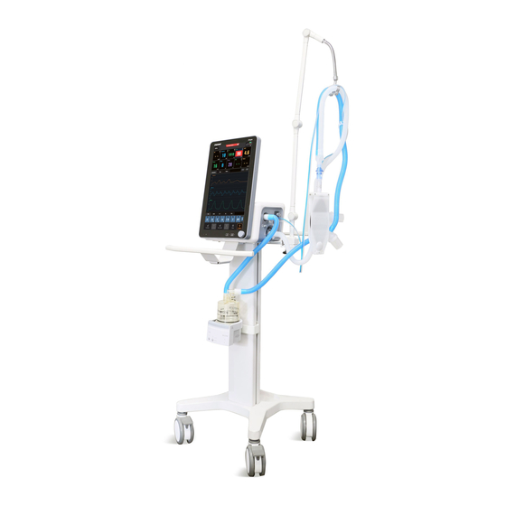
2. General Information 2.3 Potential Side Effects Noninvasive ventilation may be accompanied by some side effects. Advise the patient to immediately report any unusual chest discomfort, shortness of breath, or severe headache. Other potential side effects of noninvasive positive pressure ventilation include: ear discomfort, conjunctivitis, skin abrasions due to mask/patient interface, and gastric distention (aerophagia). - Page 31 2. General Information Display screen Circuit support arm Inspiratory bacteria filter Nebulizer device Patient circuit(dual-limb) Humidifier Trolley Figure 2-1.Ventilator with Accessories Table lists recommended patient circuits, masks/patient interfaces, and other accessories for use with the ventilator. Appendix B provides more information for parts and accessories.
-
Page 32: Main Unit
2. General Information Part Description Humidifier Humidifier listed in Appendix B. Heat and Moisture HME, commonly known as artificial nose, listed in Exchangers (HME) Appendix B. Oxygen sensor Oxygen sensor listed in Appendix B. Nebulizer VADI M-0801-EN 2.4.2 Main Unit Figure 2-2 through Figure 2-4 show the controls, indicators, and other important parts of the ventilator unit... - Page 33 2. General Information Description AC power LED LED is continuously on when AC power is connected. LED is not lit when the ventilator is not connected to an external power supply. Battery LED Lit: Indicates that the battery is being charged or the ventilator is operating on battery power.
- Page 34 2. General Information Figure 2-3.Rear view Table 2-3.Description of rear view Description USB connector RS-232 connector Connects to correcting devices and hospital information systems. Reserved for future use. Reserved for future use. Low-pressure oxygen inlet connector. See section 3.5 for more information.
- Page 35 2. General Information Description Cooling fan filter. See section 10.2.4 for more information. Equipotentiality Network connector HDMI connector Figure 2-4.Side view Table 2-4.Description of side view Description Inspiration connector(to patient) Expiratory connector(from patient) NOTE: This port is not available for RS200. Flow sensor connectors Nebulizer connector Leak test plug...
- Page 36 2. General Information (For your note.)
- Page 37 Chapter 3 3. Installations and Connections........3-1 3.1 Installing the Support Arm ..........3-1 3.2 Installing the Patient Tubing ...........3-4 3.3 Installing the Humidifier ..........3-8 3.4 Installing the Nebulizer ..........3-11 3.5 Connecting the Oxygen Supply ........3-12 3.6 Installing the Gas Cylinder ..........3-15 3.7 Installing the Oxygen Sensor ........3-15 3.8 Connecting the Power Supply ........3-17 3.9 Inspecting the Batteries ..........3-18...
-
Page 39: Installations And Connections
3. Installations and Connections Installations and Connections WARNING Do not cover or position the ventilator so as to • adversely affect its operation or performance. To reduce the risk of the device overheating and • possible burn injury, do not block the fan intake at the rear of the ventilator. - Page 40 3. Installations and Connections Fixing block knob Fixing block Tube hook Support arm joint Support bar Support arm joint Support arm joint Figure 3-1.Installing the patient tubing support arm...
- Page 41 3. Installations and Connections 1. Loosen the fixing block knob. Place the fixing block onto the handle on the side of the ventilator. 2. Tighten the fixing block knob. 3. Adjust the support arm. ◆ Support arm joint 6 or 7: to adjust the upward- bending angle of the support arm, only lift up the support bar to the desired position without the need to push the white unlocking key.
-
Page 42: Installing The Patient Tubing
3. Installations and Connections 3.2 Installing the Patient Tubing WARNING To minimize the risk of bacterial contamination or • physical damage, handle bacteria filters with care. To prevent patient or ventilator contamination, • always use a bacteria filter between the ventilator and the inspiratory limb of the patient breathing circuit. - Page 43 3. Installations and Connections Inspiratory bacteria filter Inspiratory tube Exhalation port Proximal pressure line Figure 3-2.Single-limb, without humidifier...
- Page 44 3. Installations and Connections Inspiratory bacteria filter Inspiratory tube Humidifier Water trap Exhalation valve Proximal pressure line Figure 3-3.Single-limb circuit with humidifier...
- Page 45 3. Installations and Connections Inspiratory bacteria filter Expiratory bacteria filter Inspiratory tube Expiratory tube Humidifier Water trap Y-piece Flow sensor Proximal pressure line Figure 3-4.Dual-limb circuit with humidifier Properly position the patient circuit before use on a patient. Make sure the tubing will not be pushed, pulled, or kinked during patient movement or other procedures.
-
Page 46: Installing The Humidifier
3. Installations and Connections 1. Mount the filters onto the inspiratory and expiratory ports. 2. Connect the inspiratory filter to the water trap via the tubing. Then connect the water trap to the Y piece via the tubing. 3. Connect the expiratory filter to the water trap via the tubing. - Page 47 3. Installations and Connections NOTE • The humidifier shall comply with the requirements of ISO 8185. The humidifier assembly and its installation steps described in this section are only for reference. Install a humidifier to the ventilator using the slide bracket on the trolley column.
- Page 48 3. Installations and Connections Humidifier Humidifier mounting plate Screw Humidifier bracket slot Humidifier outlet Humidifier inlet Figure 3-5.Installing the humidifier The range of the ventilator breathing system (VBS): Inspiratory and expiratory gas pathway resistance: 0 to 6 cmH O/ (L/s) at 60 L/min VBS compliance: 0 to 5 mL/cmH 3-10...
-
Page 49: Installing The Nebulizer
3. Installations and Connections 3.4 Installing the Nebulizer NOTE • Install the specified nebulizer. The nebulizer assembly and its installation steps described in this section are only for reference. Refer to the nebulizer user manual for use to install and use the nebulizer. •... -
Page 50: Connecting The Oxygen Supply
3. Installations and Connections Nebulizer connector Nebulizer Nebulizer tube Figure 3-6.A pneumatic nebulizer 3.5 Connecting the Oxygen Supply WARNING Connect the ventilator only to an appropriate • medical-grade oxygen source. Inspect the O supply connector carefully and • make sure there is no leakage. If gas leakage is significant, O concentration in the ambient environment will exceed normal atmosphere,... - Page 51 3. Installations and Connections To reduce the risk of hypoxia, connect only oxygen • to the high-pressure connector at the rear of the ventilator. CAUTION To prevent possible damage to the ventilator, • ensure that the connection to the oxygen supply is clean and unlubricated, and that there is no water in the oxygen supply gas.
- Page 52 3. Installations and Connections Oxygen supply inlet Oxygen supply hose Figure 3-7.Connecting the oxygen supply To connect the high-pressure oxygen supply as follows: 1. Before connecting the oxygen supply hose, check if the sealing ring at the gas supply connection is in good condition.
-
Page 53: Installing The Gas Cylinder
3. Installations and Connections 3.6 Installing the Gas Cylinder CAUTION Ensure that the gas cylinder is equipped with • pressure-reducing valve. Hook & Loop tapes Gas cylinder Figure 3-8.Installing the gas cylinder 1. Place the gas cylinder onto the trolley base. 2. - Page 54 3. Installations and Connections cell connection cable cell cell cover Figure 3-9.Installing the oxygen sensor 1. Rotate the O cell clockwise to install it. 2. Connect the O cell connection cable. 3. Install the O cell cover on to machine casing. CAUTION To reduce the risk of explosion, do not burn the O •...
-
Page 55: Connecting The Power Supply
3. Installations and Connections 3.8 Connecting the Power Supply WARNING To reduce the risk of strangulation, route the • power cord to avoid entanglement. CAUTION Grounding reliability can only be achieved when • equipment is connected to an appropriate voltage receptacle marked “hospital only”... -
Page 56: Inspecting The Batteries
3. Installations and Connections 1. Remove the anti-unplugging hook of power. 2. Insert the AC power cord into the AC power receptacle. 3. Install anti-unplugging hook of power to clamp the power cord in place. 3.9 Inspecting the Batteries WARNING To reduce the risk of power failure, pay close •... - Page 57 3. Installations and Connections own icon. The power source symbols in the top right- hand corner of the screen show the available power sources. A frame around a symbol indicates the current ventilator power source. A green symbol indicates a fully charged battery.
- Page 58 3. Installations and Connections (For your note.) 3-20...
- Page 59 Chapter 4 4. User Interface ..............4-1 4.1 Screen Display ...............4-1 4.2 Waveform Window............4-4 4.3 Loops Window ..............4-4 4.4 Values Window ...............4-5 4.5 Trend ................4-6 4.5.1 Graphic Trend ............4-6 4.5.2 Tabular Trend............4-8 4.5.3 Event Logbook ............4-8 4.6 Freeze ................4-10 4.6.1 Enter or Exit Freeze Status .........4-10 4.6.2 View Frozen Waveforms or Loop ......4-10 4.7 Screen Capture ............
-
Page 61: User Interface
4.User Interface 4. User Interface 4.1 Screen Display XXXXXXXXXX 12:46 2018/05/10 01:56 XXXXX XXXXX XXXXX XXXXX 1:2.0 XXXXX 30.0 15.0 -6.0 120.0 60.0 -60.0 -120.0 500.0 250.0 -100.0 Figure 4-1.Screen display... - Page 62 4.User Interface 1. Ventilation mode field Displays Standby or active ventilation mode and ventilation assist indication. 2. Patient type / Inspiratory trigger icon field Indicates current patient type. The icon for Inspiratory trigger is lung symbol. 3. Ventilation type field Displays Non-invasive or Invasive ventilation type: Displays icon when the ventilation type is Non- invasive.
- Page 63 4.User Interface 9. Power status icon field Displays the status of currently-used power supply. 10. Screen capture icon field By select this icon, you can capture and save the screen. 11. Freeze icon field Select this icon to enter freeze status. In this status, the system temporarily pauses the real-time refreshing of waveforms and loop graphs on the screen, so that you can review specific patient data.
-
Page 64: Waveform Window
4.User Interface 4.2 Waveform Window Select the [ Waveforms ] key to access the interface as shown below. The ventilator displays the real-time pressure/ time, flow/time and volume/time waveforms in the waveforms window. 30.0 15.0 -6.0 120.0 60.0 -60.0 -120.0 500.0 250.0 -100.0... -
Page 65: Values Window
4.User Interface 30.0 15.0 -6.0 -100 -100 XXXXXX XXXXXX XXXXXX XXXXXX XXXXXX XXXXXX XXXXXX Figure 4-3.Loops window 4.4 Values Window Select the [ Values ] key on the screen to open the interface as shown below. The ventilator displays the numeric patient data on the screen. -
Page 66: Trend
4.User Interface 30.0 15.0 -6.0 2720 1:4.0 0.55 Figure 4-4.Values window 4.5 Trend The system can display a rolling 72 hours of continuous trend data. Select the [ Trend&Log ] key on the screen to view trend graphic, trend table and logbook in the opened window. - Page 67 4.User Interface Graphic Trend highlights the parameter data in the corresponding alarm color if an alarm condition existed for the parameter at the time of trend record storage. XXXXXXXXXX XXXXXXXXXX XXXXXXXXXX XXXXXXXXXX Figure 4-6.Graphic trends window 1. Current cursor: The corresponding time displays above the cursor.
-
Page 68: Tabular Trend
4.User Interface 4.5.2 Tabular Trend You can view the patient’s monitored parameter data and events under the Tabular Trend tab. Trend data displays at one-minute intervals by default. XXXXXXXXXX XXXXXXXXXX XXXXXXXXXX Figure 4-7.Tabular trends window 1. Interval: You can set the display interval to [ 5 Minutes ], [ 10 Minutes ], [ 15 Minutes ], [ 30 Minutes ], [ 1 Hour ] and [ 2 Hours ]. - Page 69 4.User Interface powering on, but the time of powering down cannot be captured. The contents of the log after the alarm system has experienced a total loss of power (supply mains and internal electrical source) of a finite duration can maintain the same as that before the loss of power.
-
Page 70: Freeze
4.User Interface events are already stored, the new event overwrites the earliest one. 4.6 Freeze The freeze function’s feature is that it can pause the real-time refreshing of waveforms and spirometry loops on the screen, so that you can have a close examination of the patient’s status within this time period. -
Page 71: Screen Capture
4.User Interface 30.0 15.0 -6.0 -100 -100 XXXXXX XXXXXX XXXXXX XXXXXX XXXXXX XXXXXX XXXXXX Figure 4-9.Freeze waveforms and loops In freeze status, the [ Capture Ref. ] key is disabled, and you cannot save a loop as a reference loop. However, you can view reference loops that are already saved. -
Page 72: Lock Screen
4.User Interface XXXXXXXXXXXXXXXXXX XXXXXXXX XXXXXXXX XXXXX XXXXXXXXXXXXXXXXXX XXXXXXXXXXXXXXXXXX XXXXXXXXXXXXXXXXXX XXXXXXXXXXXXXXXXXX XXXXXXXXXXXXXXXXXX XXXXXXXXXXXXXXXXXX XXXXXXXXXXXXXXXXXX XXXXXXXXXXXXXXXXXX XXXXXXXXX Figure 4-10.View captured pictures 4.8 Lock Screen By pressing the [ Screen Lock ] key to enter locked status. During the period of screen locked, all keys on the main screen are disabled. - Page 73 Chapter 5 5. System Settings ............5-1 5.1 Date and Time Settings .............5-1 5.2 Screen Settings .................5-1 5.2.1 Screen Brightness ............5-1 5.2.2 Screen Layout ..............5-2 5.3 Export Settings ................5-3 5.3.1 Screen Capture ..............5-3 5.3.2 Patient and Setting Data ..........5-4 5.3.3 Transfer Settings ..............5-5 5.4 Basic Settings ................5-7 5.4.1 Set T-insp/I:E ..............5-7 5.4.2 Set VT/IBW ..............5-7...
-
Page 75: System Settings
5. System Settings 5. System Settings 5.1 Date and Time Settings 1. Select the system time field on the main screen to pop up time setup menu. 2. Set [ Date ] and [ Time ]. 3. Set [ Date Format ] to [ YYYY-MM-DD ], [ MM-DD-YYYY ] or [ DD-MM-YYYY ]. -
Page 76: Screen Layout
5. System Settings set day or night in [ Screen Brightness ] filed directly: 10% to 100%. Level 10% is the darkest setting and 100% is the brightest. If the ventilator is battery powered, you can select a less bright screen to save battery capacity. -
Page 77: Export Settings
5. System Settings XXXXXXXXXX XXXXXXXXXX XXXXXX XXXXXX XXXXXX XXXXXX XXXXXXXXXX XXXXXX XXXXXX XXXXXX XXXXXX XXXXXXXXXX XXXXXXXXXX XXXXXXXXXX Figure 5-3.Screen layout settings 5.3 Export Settings 5.3.1 Screen Capture The Media window displays all the screen capture files, you can preview, delete or export them. The exported file is saved in “bmp”... -
Page 78: Patient And Setting Data
5. System Settings XXXXXXXXXXXXXXXXXX XXXXXXXX XXXXXXXX XXXXX XXXXXXXXXXXXXXXXXX XXXXXXXXXXXXXXXXXX XXXXXXXXXXXXXXXXXX XXXXXXXXXXXXXXXXXX XXXXXXXXXXXXXXXXXX XXXXXXXXXXXXXXXXXX XXXXXXXXXXXXXXXXXX XXXXXXXXXXXXXXXXXX XXXXXXXXX Figure 5-4.Media window 5.3.2 Patient and Setting Data Exporting data means to export data from the ventilator, such as patient demographics, current setting parameters, current alarm limits, trend data and so on. -
Page 79: Transfer Settings
5. System Settings 4. After exporting is completed, select [ Remove USB Device ] to remove the USB device. NOTE • If you need to check the exported data, please contact the servive providers. XXXXXXXXXX XXXXXXXXXX XXXXXXXXXX XXXXXXXXXXXXXXXXXXXXXXXXXXXXXXXXXXX Figure 5-5.Export window 5.3.3 Transfer Settings You can export or import settings, while unit is in standby. - Page 80 5. System Settings filed. The system will run a check to verify that there is sufficient storage space available on the USB device. If there is sufficient space, the system will save the current settings and machine defaults to the USB device. 5.
-
Page 81: Basic Settings
5. System Settings 5.4 Basic Settings 5.4.1 Set T-insp/I:E 1. Select[ Setup ] → [ Vent ] → [ Setting ]. 2. Set [ T-insp/I:E ] and toggle between [ T-insp ] and [ I:E ] Based on [ T-insp/I:E ], adopt the corresponding T-insp or I:E ventilation parameter settings for ventilation modes (refer to Figure 5-7). -
Page 82: Set Oxygen Concentration During Suction
5. System Settings XXXXXXXXXX XXXXXXXXXX XXXXXXXXXX XXXXXXXXXX XXXXXXXXXX 100% 1.25 XXXXXXXXXX XXXXXXXXXX Figure 5-7.Ventilation settings windows 5.4.5 Set Oxygen Concentration during Suction 1. Select [ Setup ] → [ Maintain ] → [ Vent ] → [ Setting ]. 2. Set [ O % during suction ]: Set oxygen enrichment in accordance with different patient types. - Page 83 5. System Settings the screen. After Oxygen Sensor Monitoring off, the ventilator will disable relevant alarm messages and prompt messages. NOTE • The system total response time for oxygen concentration monitoring is 15s. • The time from powering on the ventilator to reaching the oxygen concentration monitoring performance specified in this manual is approximately 30s.
-
Page 84: Set Oxygen Supply
5. System Settings 5.4.7 Set Oxygen Supply 1. Select [ Setup ] → [ Maintain ] → Enter system password → [ System ]. 2. Select [ Gas supply ] and select a desired Oxygen. XXXXXXXXXX XXXXXXXXXX Figure 5-9.Oxygen supply settings window 5.4.8 Set Language 1. -
Page 85: Set Unit
5. System Settings XXXXXXXXXX XXXXXXXXXX Figure 5-10.Language settings windows 5.4.9 Set Unit Set Paw Unit 1. Select [ Setup ] → [ Maintain ] → Enter password → [ System ]. 2. Set [ Pressure Unit ]: [ cmH O ], [ hPa ] or [ mbar ]. Set Weight Unit 1. -
Page 86: System Information
5. System Settings XXXXXXXXXX XXXXXXXXXX XXXXXXXXXX XXXXXXXXXX Figure 5-11.Unit settings windows 5.4.10 System Information Version Information Select [ Setup ] → [ Info ] to check the system software version. Configuration Information Select [ Setup ] → [ Maintain ] → Enter system password → [ Configuration ] to view the configuration information of the ventilator such as ventilation mode. - Page 87 5. System Settings XXXXXXXXXXXXXXXX XXXXXXXXXXXXXXXX XXXX XXXXXXXXXX XXXXXXXXXX XXXXXXXXXXXXX XXXXXX XXXXXXXXXX XXXXXXXXXX XXXXXXXXXXXXXXXXX XXXXXXXXXX XXXXXXXXXX XXXXXXXXXX XXXXXXXXXX XXXXXXXXXX XXXXXXXXXXXXXXXX XXXXXXXXXX XXXXXX Figure 5-12.Info window 5-13...
- Page 88 5. System Settings (For your note.) 5-14...
- Page 89 Chapter 6 6. Start Ventilation ............6-1 6.1 Turning on the Ventilator ..........6-1 6.2 System Check ..............6-1 6.3 Select Patient ..............6-6 6.4 Ventilation Type ..............6-8 6.4.1 Invasive Ventilation ..........6-8 6.4.2 Non-Invasive Ventilation (NIV) ......6-9 6.4.3 Set Ventilation Type ..........6-9 6.5 Ventilation Mode ............6-10 6.5.1 Ventilation Mode and Parameters Setup .....6-10 6.5.2 Apnea Ventilation ..........6-12 6.5.3 Sigh Ventilation ............6-12...
- Page 90 6.5.16 PPS ..............6-25 6.6 Tube Resistance Compensation ........6-26 6.7 Leak Compensation ............6-27 6.8 Start Ventilation ............6-30 6.9 Standby Status .............6-30 6.10 Turn the Ventilator Off ..........6-31...
-
Page 91: Start Ventilation
6. Start Ventilation 6. Start Ventilation 6.1 Turning on the Ventilator NOTE • When the ventilator is started, the system detects whether audible alarm tones and alarm lamp function normally. If yes, the alarm lamp flashes red and yellow successively, and the speaker and the buzzer give check tones. - Page 92 6. Start Ventilation NOTE • To ensure optimum performance of the ventilator, re-do system check each time when accessories or components like tubes, humidifiers, or filters are replaced. • If the O cell is installed for the first time, or a newly replaced one, please calibrate the oxygen concentration first before running system check, otherwise the O...
- Page 93 6. Start Ventilation ◆ Exhalation Branch Test: test the expiratory valve. ◆ Pressure Sensor Test: test the pressure sensor. ◆ Leakage. ◆ Compliance. ◆ Circuit Resistance. ◆ Pressure Release Valve Test. The System Check for single-limb including the below items: ◆...
- Page 94 6. Start Ventilation During system check, if you select [ Skip ], the system stops check of this item immediately and begins to check the next item. If you select [ Stop ], the system stops all the items. When checks of all items are completed, if you select [ Retry ], the system starts a new round of check.
- Page 95 6. Start Ventilation XXXXXXXXXXXXXXXXXX XXXXXXXXXXXXXXXXXX XXXXXXXXXXX Figure 6-2.Single-limb system check prepareation & system check items...
-
Page 96: Select Patient
6. Start Ventilation 6.3 Select Patient Open the patient setting menu in standby and select the patient information: If selecting [ New Patient ], please set [ Patient ◆ Category ], [ Gender ], [ Height ]/[ IBW ] and [ Ventilation Type ] in the accessed [ New Patient ] menu. - Page 97 6. Start Ventilation XXXXXXXXXX XXXXXXXXXX XXXXXXXXXX XXXXXXXXXX XXXX XXXXXXXXXX XXXX XXXXXXXXXX XXXXXXXXXX XXXXXXXXXX XXXXXXXXXX 1.70 Figure 6-3.Ventilation settings Select [ Last Patient ] from the Standby window. The ventilator will start up with the same mode and settings as last power down. Then you can press the [ Start Ventilation ] button to start ventilation.
-
Page 98: Ventilation Type
6. Start Ventilation 6.4 Ventilation Type The ventilator provides two ventilation types: invasive and non-invasive. WARNING Check the alarm limit settings after switching over • from NIV to Invasive. 6.4.1 Invasive Ventilation Invasive ventilation means to ventilate the patient through manual airway (ET tube or Trach tube). In dual-limb invasive ventilation, the enabled ventilation modes include: ◆... -
Page 99: Non-Invasive Ventilation (Niv)
6. Start Ventilation CAUTION Do not attempt to use NIV on intubated patients. • 6.4.2 Non-Invasive Ventilation (NIV) NIV means to ventilate the patient by using a nasal mask or facial mask instead of ET tube or Trach tube. In single-limb NIV, the enabled ventilation modes include: ◆... -
Page 100: Ventilation Mode
6. Start Ventilation 6.5 Ventilation Mode NOTE • At the inspiratory phase, the ventilator will not automatically generate negative pressure. However, it may cause negative pressure because patients inhale air. • The user can set high-pressure alarm limit. If the pressure reaches the high pressure alarm limit in the inspiratory phase, the [ High Pressure ] high- level alarm is triggered. - Page 101 6. Start Ventilation Displays ventilation parameter value adjustment. XXXXXXXXXX XXXXXX XXXXXX XXXXXX XXXXXX XXXXXX XXXXXX 1.70 XXXXXX XXXXXX XXXXXX XXXXXX XXXXXX XXXXXX XXXXXXXXXX XXXXXXXXXXXXXXXXXXXXXXXXXXXXXX XXXX XXXX XXXX Figure 6-5.Ventilation mode and parameters To set ventilation mode, 1. In the ventilation mode area, select the required ventilation mode key, and the ventilation parameters can be set in this ventilation mode will be displayed in the opened menu.
-
Page 102: Apnea Ventilation
6. Start Ventilation 6.5.2 Apnea Ventilation Apnea ventilation is a backup vent mode initiated when the ventilator detects patient apnea in CPAP/PSV, VSIMV, PSIMV, V+SIMV, BPAP and APRV modes. If no spontaneous breathing time beyond apnea time, mandatory breaths are triggered with apnea ventilation. Apnea ventilation mode includes volume-controlled and pressure-controlled Ventilation. -
Page 103: Vcv
6. Start Ventilation Table 6-2.Sigh support modes Mode Sigh CPAP/PSV,BPAP,APRV Not available VCV,PCV,PRVC,PSIMV,VSIMV,V+SIMV Increase in PEEP Table 6-3.Sigh settings Parameter Description Sigh Switch for turning on sigh function. Interval Time interval between two groups of sigh. Cycles Sigh Number of sigh cycles. △... -
Page 104: Pcv
6. Start Ventilation Time of inspiration or ratio of inspiratory time to T-insp. / I:E expiratory time. PEEP Positive end-expiratory pressure. Controlled breaths per minute. Assist Assistant trigger. T-pause(%) Percent of inspiratory pause time. F-trigger /P-trigger Inspiration trigger level. 6.5.5 PCV (Pressure Controlled Ventilation Mode )... -
Page 105: Prvc
6. Start Ventilation T-slope Rise time of inspiratory pressure. F-trigger /P-trigger Inspiration trigger level. 6.5.6 PRVC (Pressure Regulated Volume Controlled Ventilation Mode) Volume-controlled mandatory breaths(PRVC) are administered at a set rate. Spontaneous respiratory efforts only trigger controlled breaths in the case of PRVC. Pressure adjustment increase of the ventilator cannot exceed 10 cmH O for the first 3 cycles and cannot... -
Page 106: Vsimv
6. Start Ventilation T-slope Rise time of inspiratory pressure. F-trigger /P-trigger Inspiration trigger level. 6.5.7 VSIMV (Volume Controlled Synchronized Intermittent Mandatory Ventilation Mode) Volume-controlled mandatory breaths(VCV) are delivered at the set rate. After mandatory breath, the patient is free to take any number of spontaneous breaths which are supported by corresponding pressure in set in the rest time of IMV cycle. -
Page 107: Psimv
6. Start Ventilation Assist Assistant trigger. Tpause(%) Percent of inspiratory pause time. F-trigger /P-trigger Inspiration trigger level. Exp% Expiration trigger level. △ P-supp. Pressure support (relative above PEEP). 6.5.8 PSIMV (Pressure Controlled Synchronized Intermittent Mandatory Ventilation Mode) Pressure-controlled mandatory breaths are delivered at the set rate. -
Page 108: Simv
6. Start Ventilation Time of inspiration or ratio of inspiratory time to T-insp. / I:E expiratory time. PEEP Positive end-expiratory pressure. f-SIMV Controlled breaths per minute. T-slope Rise time of inspiratory pressure. F-trigger /P-trigger Inspiration trigger level. Exp% Expiration trigger level. △... -
Page 109: Cpap/Psv
6. Start Ventilation Table 6-9.V+SIMV settings Parameter Description Adjustment of oxygen concentration. Tidal volume of controlled breaths. PEEP Positive end-expiratory pressure. f-SIMV Controlled breaths per minute. T-slope Rise time of inspiratory pressure. F-trigger /P-trigger Inspiration trigger level. Exp% Expiration trigger level. △... -
Page 110: Bpap
6. Start Ventilation T-slope Rise time of inspiratory pressure. F-trigger /P-trigger Inspiration trigger level. Exp% Expiration trigger level. △ P-supp. Pressure support (relative above PEEP). 6.5.11 BPAP (Bilevel Positive Airway Pressure Mode) Airway pressure switches between two pressure levels, P-low and P-high. The patient can breathe spontaneously at both pressure levels. -
Page 111: Aprv
6. Start Ventilation P-high Upper pressure level (absolute pressure). P-low Lower pressure level. T-high Time of high pressure. T-low Time of low pressure. T-slope Rise time of inspiratory pressure. F-trigger /P-trigger Inspiration trigger level. Exp% Expiration trigger level. △ P-supp. Pressure support (relative above P-low). -
Page 112: Ramp
6. Start Ventilation T-low Time of low pressure. T-slope Rise time of inspiratory pressure. 6.5.13 Ramp The ramp function is used to raise IPAP and EPAP slowly, making it easier for the patient to adapt to ventilation. The ramp time for a rise in ventilation pressure can be set by the user. -
Page 113: S/T
6. Start Ventilation 6.5.14 S/T (Spontaneous/Timed Mode) Pressure-supported breaths are triggered on a synchronised basis. Inspiration ends as soon as the flow has dropped to an adjustable percentage of peak flow. Expiration is initiated when Tinsp-max (4s) is exceeded. The mode is only available for single-limb non-invasive ventilation . -
Page 114: Pps
6. Start Ventilation 6.5.15 VS (Volume Support Ventilation Mode) VS achieves the target volume by regulating the pressure applied following an initial pressure ramp-up. VS delivers time-cycled mandatory breaths and pressure-supported spontaneous breaths. The mode is only available for single-limb non-invasive ventilation . - Page 115 6. Start Ventilation PPS provides pressure targeted ventilation in proportion to the patient’s efforts. The two types of pressure support, volume- proportional pressure support (volume assist) and flow- proportional pressure support (flow assist) can be used in combination. The mode is only available for single-limb non-invasive ventilation.
-
Page 116: Tube Resistance Compensation
6. Start Ventilation 6.6 Tube Resistance Compensation Synchronized tube resistance compensation (STRC) stands for the function of automatic tube resistance compensation. By selecting appropriate endotracheal (ET) tube or tracheostomy (Trach) tube of different diameters for the user, the ventilator can adjust gas delivery pressure automatically, so that the pressure at the end of the tube is consistent with the ventilator’s pressure setting value as much as possible. -
Page 117: Leak Compensation
6. Start Ventilation compensation during exhalation. 3. Select [ Exit ] for the system to initiate STRC. After STRC has been enabled, if you enter the STRC interface and then select [ Disable ], the system will terminate STRC immediately in the ventilation. When STRC is enabled, Ptrach waveform is displayed with the Paw waveform. - Page 118 6. Start Ventilation patients respectively. In volume control ventilation mode, the delivered gas volume is the sum of the setting TV and the amount of leakage. The leakage compensation in invasive ventilation: the upper limit of the leakage compensation is 80% of the setting TV. In pressure control ventilation mode, the ventilator regulates the flow automatically to compensate the leakage in order to maintain the inspiratory pressure.
- Page 119 6. Start Ventilation inspiration side and a minute volume of 5.0 L/min is measured on the expiration side. The lung is ventilated with an MV of 5.4 L/min. Without leakage compensation, the set TV determines the volume delivered by the ventilator. With Leakage compensation With automatic leakage compensation, the ventilator delivers 660mL on the basis of the measured leakage...
-
Page 120: Start Ventilation
6. Start Ventilation Unlimited volume compensation is inappropriate. The ventilator compensates for losses of up to 100 % of the set tidal volume TV. Due to technical tolerances, a small leakage minute volume may be displayed even if the hose system is leakproo. -
Page 121: Turn The Ventilator Off
6. Start Ventilation You must confirm that no patient is attached before entering Standby status. To prevent possible patient injury or damage to • breathing circuit from overheated gas, turn off the humidifier before entering the Standby status. 6.10 Turn the Ventilator Off Press the power switch on the rear side of machine for more than 3s in Standby status to turn the system off. - Page 122 6. Start Ventilation (For your note.) 6-32...
- Page 123 Chapter 7 7. Alarms ................7-1 7.1 Introduction ..............7-2 7.2 Alarm Categories ............7-3 7.3 Alarm Priority Levels ............7-4 7.4 Alarm Signals..............7-4 7.4.1 Alarm Lamp ............7-5 7.4.2 Audible Alarm ............7-5 7.4.3 Alarm Messages ............7-6 7.4.4 Flashing Alarm Numeric ........7-6 7.4.5 Alarm Status Symbol ..........7-6 7.5 Alarm Volume Settings ...........7-7 7.6 Alarm List ................7-8 7.7 Alarm Limits ..............7-9...
- Page 124 7.12.7 High Pressure ............7-18 7.12.8 Low Pressure ............7-18 7.12.9 High Tidal Volume ..........7-18 7.12.10 Low Tidal Volume ..........7-18 7.12.11 Low Minute Volume ........7-19 7.13 Alarm Troubleshooting Table ........7-19 7.14 Alarm Parameter ............7-27...
-
Page 125: Alarms
7. Alarms 7. Alarms NOTE • The delay time from the onset of an alarm condition to the point that the alarm signal leaves the ventilator input/output port is typically 500ms. The time it takes the message to appear on an external device such as a remote alarm depends on the characteristics of the device. -
Page 126: Introduction
7. Alarms Table 7-1.Alarm indications Alarm Alarm Alarm Alarm Type Lamp Message Alarm Audio Action Require Type Symbol Color The patient’s A sequence safety is of 5 beeps, Red, with compromised. High- repeated alarm The problem priority until the message needs alarm is immediate... -
Page 127: Alarm Categories
7. Alarms the buzzer give check tones. If not, do not use the equipment and contact servive providers immediately. • When multiple alarms of different priorities occur simultaneously, the ventilator selects the alarm of the highest priority and gives visual and audible alarm indications accordingly. -
Page 128: Alarm Priority Levels
7. Alarms 7.3 Alarm Priority Levels By severity, the ventilator’s alarms fall into three categories: high priority alarms, medium priority alarms and low priority alarms. The priorities for all alarms are preset before the ventilator leaves the factory and are not user adjustable. Table 7-2.The alarm priority and action required Alarm Priority Action Required... -
Page 129: Alarm Lamp
7. Alarms 7.4.1 Alarm Lamp If a technical alarm or physiological alarm occurs, the alarm lamp will flash. The flashing color and frequency match the alarm priority as follows: ◆ High priority alarms: the lamp quickly flashes red. ◆ Medium priority alarms: the lamp slowly flashes yellow. -
Page 130: Alarm Messages
7. Alarms 7.4.3 Alarm Messages When an alarm occurs, an alarm message will appear in the ventilator’s alarm message filed. The alarm message uses a different background color to match the alarm priority: ◆ High priority alarms: red ◆ Medium priority alarms: yellow ◆... -
Page 131: Alarm Volume Settings
7. Alarms to match the alarm priority. Red background means that the highest priority of the multiple alarm messages is high while yellow background means that the highest priority of the multiple alarm messages is medium. You can view active alarms by selecting the alarm message field. -
Page 132: Alarm List
7. Alarms XXXXXXXXXX XXXXXXXXXXXXXXXX Figure 7-1.Minimum Alarm Volume Setting 7.6 Alarm List The Alarm button is displayed on the top of screen while the active alarms happen. Click the Alarm button to open the Alarm List window which shows the most recent active alarms. -
Page 133: Alarm Limits
7. Alarms XXXXXXXXXX XXXXXXXXXX XXXXXXXXXXXXXXXXXXXX XXXXXXXXXXXXXXXXXXXXXXXXXXXXXX Figure 7-2.Active alarms window 7.7 Alarm Limits WARNING To prevent possible patient injury, avoid setting • alarm limits to extreme values, which can render the alarm system useless. To reduce patient risk from inappropriate •... - Page 134 7. Alarms is higher than the high limit or lower than the low limit. • When using the ventilator, always keep an eye on whether the alarm limits of a specific parameter are set to the appropriate values. Select [ Alarm Limit ] to set ventilation or module- related alarm limits.
-
Page 135: Nurse Call
7. Alarms XXXXXXXXXX 245 - 600 XXXXX XXXXX XXXXX XXXXX XXXXX Figure 7-4.Adjusting the alarm settings 7.8 Nurse Call The ventilator provides nurse call function that enables the ventilator to output nurse call signals to the nurse call system when an alarm meeting the user set requirements occurs. - Page 136 7. Alarms [ Continuous ]: indicates that the nurse call signal lasts until the alarm ends, i.e. the duration of a nurse call signal equals to that of the alarm. 4. Select [ Contact Type ]. [ Normally Open ]: to trigger nurse call with normally open signal.
-
Page 137: Responding To Alarms
7. Alarms reliable alarm notification combines audible and visual alarm indications with the patient’s clinical condition. 7.9 Responding to Alarms WARNING If AC power fails and the backup battery is • depleted, an audible alarm annunciates for at least 2 minutes. Immediately discontinue ventilator use and secure an alternative means of ventilation. -
Page 138: Audio Paused
7. Alarms clinical condition or an equipment problem. • Be aware that one alarm condition can induce multi-ple alarms. Normally only one or two indicate the root cause of the alarm; the rest are resultant. Your search for the causes of the alarm condition should be assisted by, but not limited to, the alarm messages displayed. -
Page 139: Alarm Off
7. Alarms Pause the alarm audio for 2 minutes by pressing the [ AUDIO PAUSED ] key on the bottom of the monitor. When the 120s countdown time is up, the AUDIO PAUSED status terminates and audible alarm tones start again. -
Page 140: Alarm Test
7. Alarms 7.12 Alarm Test The Ventilator performs a self-check during start-up and continuously during operation. You may want to run alarm tests to demonstrate the alarm’s operation. The sum of the mean alarm condition delay plus the mean alarm signal generation delay is less than 5s. 7.12.1 Low PEEP 1. -
Page 141: Low Oxygen
7. Alarms 7.12.4 Low Oxygen 1. Connect the ventilator to high-pressure oxygen supply. Set the oxygen supply type to HPO. 2. Make sure a demonstration lung is connected to the ventilator and start ventilation normally. 3. Switch off the high-pressure oxygen supply after ventilation is stable. -
Page 142: High Pressure
7. Alarms 5. Reconnect the external power supply. 6. Verify that the alarm resets and the ventilator is again powered by external power supply. 7.12.7 High Pressure 1. After the ventilator system starts up normally, connect a test lung to the ventilator and start ventilation. -
Page 143: Low Minute Volume
7. Alarms ventilation in VCV mode normally. 2. Set the VT low alarm limit to be greater than the current VTe. 3. Verify that the [ Low Tidal Volume ] alarm is activated. 7.12.11 Low Minute Volume 1. Make sure a demonstration lung is connected to the ventilator and start ventilation in VCV mode normally. - Page 144 7. Alarms Table 7-3.Physiological alarm messages Item Alarm Priority Definition Action needed Check the patient. Adjust the pressure alarm limit. The measured Check the breathing airway pressure circuit and flow sensor High High exceeds the set tubes for kinks and Pressure pressure alarm occlusions.
- Page 145 7. Alarms Item Alarm Priority Definition Action needed The measured tidal volume is Check the patient. less than the set Check and adjust the Low Tidal high alarm limit ventilator settings, Medium Volume for continuous including alarm limits. 3 mechanical Check for leaks and ventilation disconnects.
- Page 146 7. Alarms Item Alarm Priority Definition Action needed The time of failure to detect respiration Apnea Check apnea ventilation High exceeds Tapnea. Ventilation parameter setup. Start apnea ventilation mode. This alarm Apnea is given There is no need to ventilation when apnea process this alarm.
- Page 147 7. Alarms Item Alarm Priority Definition Action needed Connect to the Battery Battery external power temperature is Temperature supply. too high during High High Remove the discharge. Syst Maybe ventilator from the The system may Down sun or other heat be down.
- Page 148 7. Alarms Item Alarm Priority Definition Action needed Check the patient Patient’s PEEP tubing for leakage. is less than the Low PEEP Medium Perform System setting value to Check to test the a certain extent. leakage. Oxygen cell calibration data Cell is not within Calibrate the oxygen...
- Page 149 7. Alarms Item Alarm Priority Definition Action needed The flow sensor does not have correct Check the flow Please calibration data sensor. Calibrate Flow High or automatic Try to calibrate the Sensor recalibration of flow sensor. the flow sensor is impossible. Running System is Connect ventilator...
- Page 150 7. Alarms Item Alarm Priority Definition Action needed Blower Power Technical Contact your service Medium Supply Voltage Error (2077): providers. Error. Atmospheric Technical Contact your service Medium Pressure Sensor Fault (1042) providers. Failure. Inspiratory Technical Contact your service Medium pressure zero Fault (1044) providers.
- Page 151 7. Alarms Item Alarm Priority Definition Action needed Protecting Technical Contact your service High module Comm Fault (3005) providers. Stop. Technical Power Board Contact your service High Fault (3006) Comm Stop. providers. Technical Key Board Contact your service High Fault (3007) Comm Stop.
- Page 152 7. Alarms Item Alarm Priority Definition Action needed Spontaneous b reathing fails t o satisfy the ex Disconnect the Inspiratory p. sensitivity al patient. Restart the time too long l the time so th ventilator. at expiration is unable to end. Check the patient.
- Page 153 7. Alarms Item Alarm Priority Definition Action needed The mainstream sensor module faulty, please Please reinsert the Medium sensor reinsert the sensor. connection is sensor abnormal. Pressure reaches Check parameter Pressure Limit pressure settings, including Exceeded high alarm pressure high limit-5cmH alarm limit setting.
-
Page 154: Alarm Parameter
7. Alarms Item Alarm Priority Definition Action needed Technical Blower temp. Contact your service Medium Fault (1040) sensor failure personnel. Technical HEPA pressure Contact your service Medium Fault (1043) sensor failure personnel. Technical PEEP pressure Contact your service High Fault (1054) sensor failure personnel. - Page 155 7. Alarms Factory Parameter Range Resolution default Paw Low Limit Off, 10 ~ 83 cmH 1 cmH Adult: 0.2 ~ 100.0 L/min; MV High Limit 0.1 L/min VT*f*1.5 Pediatric: 0.2 ~ 60.0 L/min Adult: 0.1 ~ 50.0 L/min; MV Low Limit 0.1 L/min VT*f*0.6 Pediatric: 0.1 ~ 30.0 L/min;...
- Page 156 7. Alarms Factory Parameter Range Resolution default High Limit (Low-pressure 20 ~ 100% 100% oxygen supply) Low Limit (Low-pressure 18 ~ 98% oxygen supply) Inspiratory Pressure High 2 ~ 50 cmH2O 1 cmH 50 cmH Limit Inspiratory Pressure Low Off, 1 ~ 48 cmH2O 1 cmH Limit VT High Limit...
- Page 157 Chapter 8 8. Special Functions ............8-1 8.1 O ↑ (O Enrichment) ............8-1 8.2 Suctioning Tool ...............8-2 8.3 Manual Breath ...............8-2 8.4 Inspiratory Hold .............8-3 8.5 Expiratory Hold ..............8-3 8.6 Nebulization ..............8-4 8.7 P0.1 ................8-4 8.8 NIF ..................8-5 8.9 PEEPi ................8-5 8.10 PV Tool ................8-5 8.11 O Therapy ..............8-8...
-
Page 159: Special Functions
8. Special Functions 8. Special Functions 8.1 O ↑ (O Enrichment) NOTE • Oxygen alarms are suppressed while the O ↑ function is active. • ↑ is not available with low pressure oxygen mode. • The system cannot start O ↑... -
Page 160: Suctioning Tool
8. Special Functions 8.2 Suctioning Tool NOTE • P0.1, PEEPi and NIF are disabled after suction is activated. • The system cannot start O ↑ Suction in the Standby modes or O therapy modes. During suctioning, the patient’s secretion can escape of the tubing. -
Page 161: Inspiratory Hold
8. Special Functions stage of inspiration or the early stage of exhalation, the breath will not be delivered. 8.4 Inspiratory Hold NOTE • There is at least one expiratory phase between two inspiration holds. • Inspiration Hold function is disabled in CPAP mode and is supported when apnea ventilation occurs. -
Page 162: Nebulization
8. Special Functions to 30s additional. 8.6 Nebulization CAUTION Remove the nebulizer after nebulization,otherwise • the ventilation may be affected. The remaining nebulizer drug will affect the • surrouding air. NOTE • For adults or pediatric patients, the nebulization flow of ventilator is zero when the inspiratory flow is less than 15 L/min. -
Page 163: Nif
8. Special Functions 1. Select the [ Function ] ->[ Diagnostics ] ->[ P0.1 ]. 2. Press the [ Start ] key to start the measurement, and the result will be displayed after the measurement is completed. 8.8 NIF The Negative Inspiratory Force (NIF) maneuver is used to determine the patient’s ability to pull a negative inspiratory pressure against an occluded airway. - Page 164 8. Special Functions within one minute after nebulization or suction, within one minute after last PV loop test. • The PV tool function is not recommended when there is great leakage or when the patient has spontaneous breathing. The relevant characteristic points the PV tool function provides are only for your reference.
- Page 165 8. Special Functions When you select [ Cursor 1 ] or [ Cursor 2 ], you can move the position of the cursor to determine the characteristic points. The system also displays the volume value and pressure value in the inspiratory limb and expiratory limb corresponding to the cursor position and displays the compliance of these limbs.
-
Page 166: O Therapy
8. Special Functions 8.11 O Therapy therapy is a method to increase O concentration in the airway at normal pressure through simple tube connections. O therapy is a way for hypoxia prevention or treatment, providing O concentration higher than that in the air. Therapy, select the [ Standby ] ->... - Page 167 Chapter 9 9. Maintenance ..............9-1 9.1 Instructions ..............9-1 9.2 Preventive Maintenance ..........9-2 9.3 Battery Maintenance ............9-5 9.3.1 Battery Use Guidance ...........9-7 9.3.2 Battery Performance Checking......9-7 9.3.3 Battery Performance Conditioning......9-8 9.3.4 Battery Storage .............9-9 9.3.5 Battery Recycling ..........9-10 9.4 Pressure and Flow Zeroing ..........9-10 9.5 Flow Calibration ............9-10 9.6 Oxygen Concentration Calibration ........9-12 9.7 Electrical Safety Inspection ..........9-14...
-
Page 169: Maintenance
9. Maintenance 9. Maintenance WARNING To reduce the risk of electric shock, power down • the ventilator and disconnect it from AC power before cleaning or servicing it. Movable parts and removable components may • present a pinch or a crush hazard. Use care when moving or replacing system parts and components. -
Page 170: Preventive Maintenance
9. Maintenance Used equipment may contain blood and body fluids. Movable parts and removable components may • present a pinch or a crush hazard. Take care to move or replace system parts and components. Do not use lubricants that contain oil or grease, •... - Page 171 9. Maintenance between patients and at regular intervals (or as stated by the manufacturer). To prevent possible patient injury, inspect and • verify the proper operation of the exhalation port regularly during use. CAUTION Because some environments cause a quicker •...
- Page 172 9. Maintenance Interval Part/accessory Procedure Breathing circuit (including mask, inspiratory filter, Replace with sterilized or flow sensor, new single use parts. Run Each patient or as nebulizer jar, the flow sensor calibration. necessary expiratory valve cover and membrane). Entire ventilator. Run the system self-check.
-
Page 173: Battery Maintenance
9. Maintenance Interval Part/accessory Procedure Replace the O cell if it is damaged. [ Note ] If ICU work normally, the service life of chemical O Sensor is one year. The service life of sensor is an approximate Oxygen cell specification only. - Page 174 9. Maintenance their life. Charge the batteries before they are depleted. • Inspect and replace batteries regularly. Battery life depends on how frequent and how long it is used. For a properly maintained and stored lithium battery, its life expectancy is approximately 2 years. For more aggressive use models, life expectancy can be shortened.
-
Page 175: Battery Use Guidance
9. Maintenance Indicates the capacity of the battery is 81%-100%. Indicates the capacity of the battery is 61%-80%. Indicates the capacity of the battery is 41%-60%. Indicates the capacity of the battery is 21%-40%. Indicates the capacity of the battery is 0%-20%. Indicates the battery is charging. -
Page 176: Battery Performance Conditioning
9. Maintenance • If obvious signs of damage are detected on the battery or the battery recharging is failed, replace the battery and recycle it properly. Check battery performance once every six months. Checking battery performance is also required before ventilator repair is carried out or when battery is doubted to be the source for ventilator failure. -
Page 177: Battery Storage
9. Maintenance Condition batteries when they are put into use for the first time. A complete battery conditioning cycle is: uninterrupted charging, followed by uninterrupted discharging until the ventilator shuts off, and then uninterrupted charging. Condition batteries regularly to maintain their service life. Follow the below steps to condition batteries: 1. -
Page 178: Battery Recycling
9. Maintenance 9.3.5 Battery Recycling If obvious signs of damage are detected on the battery or the battery recharging has failed, replace the battery and recycle it properly. Dispose of the battery in compliance with the local laws regulating the disposal of such product. - Page 179 9. Maintenance • It is recommended not to connect the humidifier to the ventilator before calibration. • In case of calibration failure, check for relevant malfunctioning alarm and then troubleshoot it if there is. If it still fails or great measurement error occurs after calibration, replace the flow sensor and repeat the above operation.
-
Page 180: Oxygen Concentration Calibration
9. Maintenance 6. After the calibration completed, the message indicating calibration failure is displayed if the calibration is failed. In this case, you need to do the calibration again. XXXXXXXXXXXXX XXXXXXXXXXXXXXXXXXXXXXXXXXXXXXXXXXXXXXXXXXXXXXXXXXXXXXXXXXXXXXXXX XXXXXXXXXXXXXXXXXXXXXXXXXXXXXXXXXXXXXXXXXXXXXXXXXXXXXXXXXXXXXXXXX XXXXXXXXXXXXXXXXXXXXXXXXXXXXXXXXXXXXXXXXXXXXXXXXXXXXXXXXXXXXXXXXX XXXXXXXXXXXXXXXXXXXXXXXXXXXXXXXXXXXXXXXXXXXXXXXXXXXXXXXXXXXXXXXXX XXXXXXXXXXXXX XXXXXXXXXXXXX XXXXXXXXXXXXXXXXXXXXXXXXXXXXXXXXXXXXXXXXXXXXXXXXXXXXXXXXXXXXXXXXX Figure 9-2.Flow calibration 9.6 Oxygen Concentration Calibration NOTE •... - Page 181 9. Maintenance affects the partial pressure of oxygen. Do oxygen concentration calibration again when atmospheric pressure has changed. • Increasing to periodical pressure of 10 kPa (100 O) has no effect upon oxygen concentration monitoring accuracy. • In case of calibration failure, check for relevant malfunctioning alarm and then troubleshoot it if there is.
-
Page 182: Electrical Safety Inspection
9. Maintenance sensor. XXXXXXXXXXXXX XXXXXXXXXXXXXXXXXXXXXXXXXXXXXXXXXXXXXXXXXXXXXXXXXXXXXXXXXXXXXXXXX XXXXXXXXXXXXXXXXXXXXXXXXXXXXXXXXXXXXXXXXXXXXXXXXXXXXXXXXXXXXXXXXX XXXXXXXXXXXXXXXXXXXXXXXXXXXXXXXXXXXXXXXXXXXXXXXXXXXXXXXXXXXXXXXXX XXXXXXXXXXXXXXXXXXXXXXXXXXXXXXXXXXXXXXXXXXXXXXXXXXXXXXXXXXXXXXXXX XXXXXXXXXXXXX XXXXXXXXXXXXX XXXXXXXXXXXXXXXXXXXXXXXXXXXXXXXXXXXXXXXXXXXXXXXXXXXXXXXXXXXXXXXXX Figure 9-3.O calibration 9.7 Electrical Safety Inspection NOTE • Perform an electrical safety inspection after servicing or routine maintenance. Before performing the electrical safety inspection, ensure that all the covers, panels, and screws are correctly installed. - Page 183 9. Maintenance ◆ b. Test the earth resistance with a current of 25A. ◆ c. Verify the resistance is less than 0.1 ohms (100 mohms). ◆ d. If the resistance is larger than 0.1 ohms (100 mohms) but less than 0.2 ohms (200 mohms), disconnect the AC power cord and plug the probe, that was previously plugged in the protective earth terminal of the AC power cord, into the protective...
- Page 184 9. Maintenance mA)on the BF type applied parts; that the maximum leakage current in the middle four tests is not higher than 50 μA(0.05 mA)on the CF type applied parts and not higher than 500 uA(0.5 mA)on the BF type applied parts;...
- Page 185 Chapter 10 10. Cleaning and Disinfection ........10-1 10.1 Methods ...............10-2 10.2 Part Disassemble ............10-6 10.2.1 Expiration Valve Assembly and Membrane ..10-6 10.2.2 Inspiratory Valve Assembly ........10-7 10.2.3 HEPA Filter and Air Intake Dust Filter ....10-8 10.2.4 Cooling Fan Dust Filter ........10-9 10.2.5 Patient Tubing ..........10-10 10.2.6 Humidifier ............
-
Page 187: Cleaning And Disinfection
10. Cleaning and Disinfection 10. Cleaning and Disinfection WARNING Read the material safety data sheet for each • cleaning agent. Reuse of undisinfected reusable accessories or • components may cause cross-contamination. Wear gloves and safety glasses. A damaged • sensor can leak and cause burns (contains potassium hydroxide). -
Page 188: Methods
10. Cleaning and Disinfection with body fluids and expired gases during both NORMAL CONDITION and SINGLE FAULT CONDITION. • Do not use organic, halogenated, or petroleum based solvents, anesthetic agents,glass cleaners, acetone, or other harsh cleaning agents. • Do not use abrasive cleaning agents (such as steel wool, silver polish, or cleaner). - Page 189 10. Cleaning and Disinfection Wipe : wipe with a damp cloth immersed in medium- or high-efficiency disinfectant and then wipe off the remaining detergent with a dry lint free cloth. Immersion : immerse it in medium- or high-efficiency disinfectant (alcohol or isopropyl alcohol, etc.) for more than 30 minutes (recommended time).
- Page 190 10. Cleaning and Disinfection Inspiration valve √ √ √ assembly necessary Inspiration valve assembly dust √ √ necessary filter Expiration valve Each patient assembly (except √ √ √ /weekly membrane) Expiration valve Each assembly (except patient/ √ √ √ membrane) weekly /weekly √...
- Page 191 10. Cleaning and Disinfection Ultraviolet radiation for 30 to 60 minutes (recommended time). NOTE • As necessary: shorten the cleaning and disinfection intervals if the equipment is used in dusty environment to ensure that the equipment surface is not covered by dust. •...
-
Page 192: Part Disassemble
10. Cleaning and Disinfection 10.2 Part Disassemble 10.2.1 Expiration Valve Assembly and Membrane Expiration valve handwheel Expiration valve membrane Figure 10-1.Disassemble expiration valve and membrane To disassemble: 1. Rotate the expiration valve handwheel until the indicating arrow on the handwheel is aligned with the unlock position. -
Page 193: Inspiratory Valve Assembly
10. Cleaning and Disinfection Push the expiratory valve assembly into the corresponding connector on the ventilator horizontally until it is fully inserted. Then rotate the expiratory valve handwheel (and press the handwheel in the direction the expiratory valve is installed) until the indicating arrow on the handwheel is aligned with the lock position. -
Page 194: Hepa Filter And Air Intake Dust Filter
10. Cleaning and Disinfection To install: Push the inspiratory valve assembly into the corresponding connector on the ventilator horizontally until it is fully inserted. Ensure that the inspiration valve is fully locked by the button. 10.2.3 HEPA Filter and Air Intake Dust Filter HEPA filter Air intake dust filter Cover... -
Page 195: Cooling Fan Dust Filter
10. Cleaning and Disinfection 1. Align the HEPA filter with the corresponding slot, and push in the direction the HEPA filter is installed. Fasten the HEPA filter latch. 2. Check whether the key placement above HEPA has been installed correctly. 3. -
Page 196: Patient Tubing
10. Cleaning and Disinfection 2. Pinch the backup air supply cooling fan dust filter with two fingers and remove. To install: 1. Place the fan dust filter of backup air supply in the corresponding position inside the cooling fan. 2. Close the cover. 10.2.5 Patient Tubing WARNING To minimize the risk of bacterial contamination or... -
Page 197: Humidifier
10. Cleaning and Disinfection Inspiratory filter Expiratory filter Humidifier Inspiratory water trap Expiratory water trap Support arm hook Figure 10-5.Disassemble patient tube 10.2.6 Humidifier NOTE • The humidifier shall comply with the requirements of ISO 8185. The humidifier assembly, its installation and disassembling steps described in this section are only for reference. -
Page 198: Nebulizer
10. Cleaning and Disinfection Humidifier Humidifier mounting plate Screw Humidifier bracket slot Humidifier outlet Humidifier inlet Figure 10-6.Disassemble humidifier To disassemble: 1. Disconnect the tubes from the humidifier. 2. Remove the screw. 3. Lift up the humidifier to remove it from the humidifier bracket fixed seat. - Page 199 10. Cleaning and Disinfection Nebulizer connect Nebulizer Nebulizer tube Figure 10-7.Disassemble nebulizer To disassemble: 1. Pull out the nebulizer tube from the nebulizer connector. 2. Pull out the nebulizer tube from the nebulizer and remove the nebulizer. To install: Refer to 3.4 Installing the nebulizer.
- Page 200 10. Cleaning and Disinfection (For your note.) 10-14...
- Page 201 Chapter 11 11.Specifications ............11-1 11.1 Physical Characteristic ........11-1 11.2 Environmental Requirements ......11-2 11.3 Electrical Specifications ........11-4 11.4 Pneumatic Specifications ........11-5 11.5 Control Settings ...........11-6 11.6 Monitored Parameters .........11-10 11.7 Configuration Specifications ........11-15 11.8 Factory Default Settings ........11-17 11.9 Residual Risk .............11-26 11.10 Other Technical Data ........11-26...
-
Page 203: Specifications
11. Specifications 11. Specifications 11.1 Physical Characteristic 11-1... -
Page 204: Environmental Requirements
11. Specifications Table 11-1.Physical characteristic Parameter Specification 327 mm * 310 mm * 493 mm 664mm * 600 mm * 1465 mm (with Dimensions (L*W*H) trolley) Note: The tolerance of all dimensions is ±5mm. Approximately 11.7 kg Weight Approximately 32.5 kg (with trolley) Size: 18.5 TFT color touch screen Screen Resolution: 1920*1080... - Page 205 11. Specifications 1000 2000 3000 4000 5000 Altitude(m) Figure 11-1.Altitude/Pressure changes NOTE • The environment required for oxygen sensor is listed as follows table. Relative humidity Barometric Item Temperature (non-condensing) pressure Operating 0 to 50 ℃ 0 to 99 %RH 0.6 to 2 bar -20 to 50 ℃...
-
Page 206: Electrical Specifications
11. Specifications 11.3 Electrical Specifications Table 11-3.Electrical specification Parameter Specification AC voltage: 100 to 240 V AC frequency: 50 to 60 Hz Input power AC current: 2.5 to 1.1 A Fuse: T3.15 AH/250 V Class I / Internally powered equipment; Type BF applied part;... -
Page 207: Pneumatic Specifications
11. Specifications 11.4 Pneumatic Specifications Table 11-4.Pneumatic specification Parameter Specification Pressure:280 to 600 kPa/41 to 87 psi/ 2.8 to 6.0 bar; High-pressure oxygen inlet Flow: 40 to 120 L/min STPD Connector: NIST or DISS Pressure: < 100 kPa/1 bar/14.5 psi Low-pressure oxygen Flow: ≤... -
Page 208: Control Settings
11. Specifications Adult disposable circuit (including inspiratory valve, adult disposable breathing tubes, water trap, expiration valve): ≤ 4 mL/ Adult reusable circuit (including inspiratory valve, adult reusable breathing tubes, water trap, expiration valve, Y piece): ≤ 2mL/ Compliance Pediatric disposable circuit (including inspiratory valve, pediatric disposable breathing tubes, water trap, expiration valve): ≤... - Page 209 11. Specifications Parameter Range Resolution Accuracy ±1 /min Relation expanded 1 to 80 /min 1 /min uncertainty: k=2, U=2.22% f-SIMV 1 to 80 /min 1 /min ±1 /min 2:1 to 1:4: ±10% 1:10 to 4:1 Other range: ±15% ±0.1s or ± 10%, T-insp.
- Page 210 11. Specifications Parameter Range Resolution Accuracy ±(2.0 cmH O + 5% of ΔP-apnea 5 to 80 cmH 1 cmH set value) Adult:100 to Adult:10 mL 2000mL ±(10 mL + 10% of VT-apnea Pediatric: 1 Pediatric:20 to set value) 300mL f-apnea 1 to 80 /min 1 /min ±1 /min...
- Page 211 11. Specifications Abbreviation Range Resolution Accuracy ±(5 vol.% +1% of 21 to 100 vol.% 1 vol.% set value) 4 to 60 /min 1 /min ±1 /min ±0.1s or ± 10% of set value, T-insp. 0.3 to 3.00 s 0.05 s whichever is greater ±(2.0 cmH...
-
Page 212: Monitored Parameters
11. Specifications Oxygen concentration controlling response time The responded time of the oxygen concentration in the delivered volume to change from a volume fraction of 21 % to 90 % of the maximum settable oxygen concentration: When TV=500 mL, f=10 /min, I:E=1:2, ≤ 50 s ; When TV=150 mL, f=20 /min, I:E=1:2, ≤... - Page 213 11. Specifications Parameter Range Resolution Accuracy ±8 % of actual ≥ 3.0: 0.1 L/min reading or ± 0.3 L/ 0~99.9 L/min < 3.0: 0.01 L/min min whichever is greater ±8 % of actual ≥ 3.0: 0.1 L/min reading or ± 0.3 L/ MV-leak 0~99.9 L/min <...
- Page 214 11. Specifications Parameter Range Resolution Accuracy ±5 % of actual reading or ±1 / f-total 0~99 /min 1 /min min, whichever is greater ±5 % of actual reading or ±1 / f-mand. 0~99 /min 1 /min min, whichever is greater ±5 % of actual reading or ±1 / f-spn.
- Page 215 11. Specifications Parameter Range Resolution Accuracy ± (1 J/min + 15 % 0~100 J/min 1 J/min of actual reading) ±(3 1/( min·L) RSBI 0~999 1/(min·L) 1 1/(min·L) ±15 % of actual reading) ± (2 cmH O +4% of -45-0 cmH 0.1 cmH actual reading) ±...
- Page 216 11. Specifications Abbreviation Range Resolution Accuracy Volume 0 to 4000 mL ± (2 cmH O + 4 % 0 to 50 cmH 1 cmH of actual reading) ± (2 cmH EPAP 0 to 50 cmH 1 cmH 4 % of actual reading) ±...
-
Page 217: Configuration Specifications
11. Specifications 11.7 Configuration Specifications Table 11-10.Feature specifications Model Features RS300 RS200 RS100 CPAP (Continuous √ √ Positive Airway Pressure) PCV (Pressure Control √ √ √ Ventilation) PPS (Proportional √ √ Pressure Support) S/T (Spontaneous/ √ √ Timed) VS (Volume Support) √... - Page 218 11. Specifications Model Features RS300 RS200 RS100 Therapy Mode Oxygen Therapy √ √ √ Monitoring Waveform √ √ √ Numeric √ √ √ Loop √ √ √ Trend √ √ √ NIV(Non Invasive √ √ √ Ventilation) Apnea Ventilation √ √...
-
Page 219: Factory Default Settings
11. Specifications Items Range 6mL/kg , 7mL/kg , 8mL/kg , 9mL/kg , 10mL/kg , VT/IBW 11mL/kg , 12mL/kg Monitoring ON / OFF System Date System Time Date Format YYYY-MM-DD, MM-DD-YYYY, DD-MM-YYYY Time Format 12h, 24h 11.8 Factory Default Settings Table 11-12.Ventilation mode settings Mode Parameter Factory Default Settings... - Page 220 11. Specifications Mode Parameter Factory Default Settings % (HPO) Adult: 10 /min Pediatric: 20 /min PEEP 3 cmH △ P-insp. 15 cmH Adult: 2.00 s T-insp. Pediatric: 1.00 s PCV (INV) T-slope 0.2 s Adult: 2.0 L/min F-trigger Pediatric: 1.0 L/min Assist Sigh Sigh Interval...
- Page 221 11. Specifications Mode Parameter Factory Default Settings % (HPO) f-SIMV Adult: 5 /min PEEP 3 cmH △ P-insp. 15 cmH △ P-supp. 0 cmH T-insp. Adult: 2.00 s T-slope. 0.2 s Adult: 2.0 L/min F-trigger Pediatric: 1.0 L/min Exp% Auto Δ...
- Page 222 11. Specifications Mode Parameter Factory Default Settings Adult: 2.0 L/min F-trigger Pediatric: 1.0 L/min Exp% Auto Δ P-apnea 15 cmH f-apnea 1 /min Adult: 2.00 s Apnea T-insp. Pediatric: 1.00 s Adult: max(7*mL/kg*IBW, 100) VT-apnea Pediatric: 7*mL/kg*IBW Apnea Vent Sigh Sigh Interval 1 min Sigh Cycles...
- Page 223 11. Specifications Mode Parameter Factory Default Settings Adult: max(7*mL/kg*IBW, 100) VT-apnea Pediatric: 7*mL/kg*IBW Apnea Vent Sigh Sigh Interval 1 min Sigh Cycles Δ int.PEEP 5 cmH % (HPO) △ P-supp. 0 cmH T-slope 0.2 s P-high 15 cmH P-low 3 cmH Adult: 1.7 s T-high Pediatric: 0.7 s...
- Page 224 11. Specifications Mode Parameter Factory Default Settings Adult: max(7*mL/kg*IBW, 100) Pediatric: 7*mL/kg*IBW % (HPO) Adult: 10 /min Pediatric: 20 /min PEEP 3 cmH Adult: 2.00 s T-insp. Pediatric: 1.00 s PRVC T-slope 0.2 s Adult: 2.0 L/min F-trigger Pediatric: 1.0 L/min Assist Sigh Sigh Interval...
- Page 225 11. Specifications Mode Parameter Factory Default Settings Adult: max(7*mL/kg*IBW, 100) VT-apnea Pediatric: 7*mL/kg*IBW % (HPO) CPAP 4 cmH Rise Ramp CPAP Δ P-apnea 5 cmH f-apnea 1 /min Adult: 2.00 s Apnea T-insp. Pediatric: 1.00 s % (HPO) Adult: 10 /min Pediatric: 20 /min Adult: 2.00 s T-insp.
- Page 226 11. Specifications Mode Parameter Factory Default Settings Adult: max(7*mL/kg*IBW, 100) Pediatric: 7*mL/kg*IBW % (HPO) Adult: 10 /min Pediatric: 20 /min I-trigger E-cycle EPAP 10 cmH Rise P-min 10 cmH P-max 20 cmH % (HPO) Adult: 10 /min Pediatric: 20 /min Adult: 2.00 s T-insp.
- Page 227 11. Specifications Table 11-14.System configuration Items Factory Default Setting Screen brightness T-insp./I:E T-insp. Height/IBW Height IV Apnea Mode Pressure Control VT/IBW 7mL/kg Monitoring System Date 2017.01.01 System Time 00:00:00 Date Format YYYY-MM-DD Time Format Paw Unit Weight Unit Supply Tube Compensation: Disable Tube I.D.: 8.0mm (Adult) 5.0mm (Pediatric) STRC...
-
Page 228: Residual Risk
11. Specifications 11.9 Residual Risk Table 11-15.Residual risk Number Risk item Residual Risk The battery is charging and the charging voltage is over than the manufacturer specified. The battery is charging It will lead to overcharging and the charging current is and cause fire or safety risk. - Page 229 11. Specifications Parameter Specification ≤ 6.0 cmH O at 2.5 L/min, using a 10 mm circuit Inspiratory and expiratory ≤ 6.0 cmH O at 15 L/min, using a 15 mm pressure drop following circuit equipment failure ≤ 6.0 cmH O at 30 L/min, using a 22 mm circuit 45 to 85 dB(A) (primary alarm) Audio alarm loudness...
- Page 230 11. Specifications (For your note.) 11-28...
- Page 231 Appendix A. Pneumatic Diagram ............A-1 B. Parts and Accessories ............. B-1 C. Communications Interface ..........C-1 D. EMC Declarations ............D-1 E. Compliance ............... E-1 F. Neonatal Ventilation ............F-1 Glossary ................. 1...
-
Page 233: Pneumatic Diagram
A. Pneumatic Diagram A. Pneumatic Diagram Figure A-1.Pneumatic diagram... - Page 234 A. Pneumatic Diagram Table A-1.Description of pneumatic diagram Symbol Name Symbol Name Low-pressure Air Flow sensor of the inlet mixed gas Low-pressure O Insp. hold (Low) Inspiratory hold valve inlet valve High-pressure O (High) Check valve inlet Filter Pressure release valve Dust filter Rinse valve Switch valve...
-
Page 235: Parts And Accessories
B. Parts and Accessories B. Parts and Accessories WARNING Use only accessories specified in this chapter. • Using other accessories may cause incorrect measured values or equipment malfunction. Check the accessories and their packages for • damage. Do not use them if any sign of damage is detected. - Page 236 Face mask, size medium 5000-000014-00 Face mask, size large 5000-000022-00 Test lung 50105-000004-00 VADI Clipped test lung 50105-000002-00 VADI HEPA filter 11006-000002-00 Resvent Oxygen supply hose assembly-NIST connector, 11003-000004-00 GENTEC European standard Nebulizer(M-0801-EN) 50199-000018-00 VADI Oxygen supply hose assembly-DISS connector, 11003-000003-00...
- Page 237 B. Parts and Accessories Item Description Part No. Manufacturer Power cord with continental European 0100-000004-00 JINHE plug, 3-pin Flow sensor, adult 60201-000068-00 RESVETN Flow sensor, adult 60201-000071-00 RESVETN Power cord (Brazil) 05601-000004-00 JINHE Power cord ( India) 05601-000003-00 JINHE Power cord (UK) 05601-000002-00 JINHE Power cord (Korea)...
- Page 238 B. Parts and Accessories Item Description Part No. Manufacturer Support arm 10199-000001-00 RESVETN Inspiratory valve assembly, 60201-000009-00 Resvent reusable Expiratory valve assembly, 60201-000007-00 Resvent reusable Air inet dust filter 10006-000016-00 Resvent Fan dust filter 10006-000017-00 Resvent...
-
Page 239: Communications Interface
C. Communications Interface C. Communications Interface WARNING Connect to the ventilator only items that • are specified as part of or compatible with the ventilator system. Additional equipment connected to medical electrical equipment must comply with the respective IEC or ISO standards. Furthermore, all configurations shall comply with the requirements for medical electrical systems (see IEC 60601-1-1 or clause 16 of edition 3 of IEC... - Page 240 C. Communications Interface (For your note.)
-
Page 241: Emc Declarations
D. EMC Declarations D. EMC Declarations NOTE • Using accessories other than those specified may result in increased electromagnetic emission or decreased electromagnetic immunity of the equipment. • The ventilator or its components should not be used adjacent to or stacked with other equipment. If adjacent or stacked use is necessary, the ventilator or its components should be observed to verify normal operation in the configuration in which it... -
Page 242: Compliance
D. EMC Declarations Table D-1.Guidance and manufacturer's declaration- electromagnetic emissions Electromagnetic environment - Emissions test Compliance guidance The ventilator uses RF energy only for its internal function. Therefore, its RF emissions are RF emissions CISPR 11 Group 1 very low and are not likely to cause any interference in nearby electronic equipment. - Page 243 D. EMC Declarations IEC 60601-1-2 test Compliance Electromagnetic Immunity test level level environment - guidance ±1 kV Mains power quality ±1 kV line(s) to line(s) to Surge IEC should be that of a typical line(s) ±2 kV line(s) line(s) ±2 61000-4-5 commercial or hospital to earth...
- Page 244 D. EMC Declarations IEC 60601-1-2 test Compliance Electromagnetic Immunity test level level environment - guidance Portable and mobile RF communications equipment should be used no closer to any part of the ventilator, including cables, than the 3 Vrms 150 recommended separation kHz to 80 MHz distance calculated from (for RGM, SpO...
- Page 245 D. EMC Declarations IEC 60601-1-2 test Compliance Electromagnetic Immunity test level level environment - guidance Note 1: At 80 MHz and 800 MHz, the separation distance for the higher frequency range applies. Note 2: These guidelines may not apply in all situations. Electromagnetic propagation is affected by absorption and reflection from structures, objects and people.
- Page 246 D. EMC Declarations Table D-3.Recommended separation distances between portable and mobile RF communications equipment and the ventilator Rated maximum Separation distance in meters (m) according to output power of frequency of the transmitter transmitter(W) 150 kHz to 80 80 kHz to 800 800 MHz to 2.5 0.01 0.12...
- Page 247 E. Compliance E. Compliance IEC Standard EN Standard Designation General requirements IEC 60601-1 EN 60601-1 for basic safety and essencial performance Electromagnetic IEC 60601-1-2 EN 60601-1-2 compatibility IEC 60601-1-6 EN 60601-1-6 Usability IEC 62366-1 EN 62366-1 Usability IEC 60601-1-8 EN 60601-1-8 Alarm systems Repiratory gas ISO 80601-2-55...
- Page 248 E. Compliance (For your note.)
-
Page 249: Neonatal Ventilation
F. Neonatal Ventilation F. Neonatal Ventilation WARNING Check the neonatal flow sensor before use. DO • NOT use the neonatal flow sensor if the sensor’s main body, tubing or connector is damaged or occluded. DO NOT use the neonatal flow sensor if the •... - Page 250 F. Neonatal Ventilation position where the tubing or cables may become easily entangled, knotted or detached. Otherwise, this may result in hypercarbia or hypoxemia. Please DO NOT apply pressure to the neonatal flow • sensor by pulling the neonatal flow sensor tubing, or rotate the neonatal flow sensor.
- Page 251 F. Neonatal Ventilation confirmation of the expiration valve assembly must be done before connecting the tube. If it is not a neonatal expiration valve assembly, please replace it. 1-Neonatal expiration valve assembly 2-Adult/pediatric expiration valve assembly To disassemble: 1. Rotate the expiration valve handwheel until the indicating arrow on the handwheel is aligned with the unlock position.
- Page 252 F. Neonatal Ventilation F.2 Installing Neonatal Tubing 3.2 Installing the Patient Tubing Refer to .The use of a humidifier is recommended when installing neonatal tubing. 1. Mount the filters onto the inspiratory and expiratory ports. 2. Connect the inspiratory filter to the humidifier inlet via the neonatal tube.
- Page 253 F. Neonatal Ventilation F.3 System check 6.3 System check Refer to . Please make sure that the system check is completed before initiation of neonatal ventilation. F.4 Start Ventilation WARNING Before using the ventilator on the patient, check • that the oxygen concentration in the delivered gas is consistent with the setting value.
- Page 254 F. Neonatal Ventilation When the neonatal flow sensor returns to normal, the ventilator will switch back to the original ventilation mode automatically. F.6 Neonatal Flow Sensor calibration Please perform calibration of the neonatal flow sensor when the measured value has a great deviation. Refer 9.5 Flow sensor calibration NOTE •...
- Page 255 F. Neonatal Ventilation Table F-1.Control settings Parameter Range Resolution Accuracy 20 to 2000mL: ±(10mL+10% of setting) 2 to 300 mL 1 mL 2 to 20mL: ±(2mL+10% of setting) 1 to 150 /min 1 /min ±1 /min f-SIMV 1 to 150 /min 1 /min ±1 /min ±0.1s or ±10% of...
- Page 256 F. Neonatal Ventilation F.8 Monitored Parameters For all measured and computed variables that are displayed or used for control, the low pass filtering and moving average smoothing techniques is used. NOTE • The unlisted parameters are the same as the corresponding parameters of adult.
-
Page 257: Glossary
Glossary Glossary Apnea Inspiration time set in apnea ventilation mode. T-insp. Apnea Vent Apnea ventilation. Assist Assisted trigger function. APRV Airway Pressure Release Ventilation. ATPD Ambient Temperature and Pressure Dry. BPAP Bilevel Positive Airway Pressure. BTPS Body Temperature and Pressure Saturated C-dyn. - Page 258 Glossary Inspiratory positive airway pressure. A control setting. The application and maintenance of pressure above IPAP atmospheric at the airway throughout the inspiration phase of positive-pressure mechanical ventilation. I-trigger Inspiratory trigger sensitivity The accumulated expired tidal volume in one minute. The accumulated leakage (inspiratory volume minus MV-leak expiratory volume) in one minute.
- Page 259 Glossary PRVC Pressure Regulated Volume Control. Pressure Synchronized Intermittent Mandatory PSIMV Ventilation. Patient leak, the leak resulting from leaks around the mask Pt.-leak or from unintentional leaks in the circuit. A monitored parameter shown when the intentional leak is known. Patient trigger, Percentage of patient-triggered breaths.
- Page 260 Glossary T-high Time of High Pressure Inspiratory duty cycle. Inspiratory time divided by Ti/Ttot. total cycle time, averaged over 8 breaths, a monitored parameter. Time of Inspiration. The duration of inspiration in one T-insp. breathing cycle. T-low is the time that the ventilator will hold the low T-low pressure level.
- Page 261 Glossary Intermittent Positive End-Expiratory Pressure. It is a Δ int.PEEP relative value relative to PEEP. Δ P-insp. It is a relative value relative to PEEP. Pressure Support Level. It is a relative value relative to Δ P-supp. PEEP or P-low. Pressure of Apnea Ventilation.
Need help?
Do you have a question about the iHope RS Series and is the answer not in the manual?
Questions and answers
START VENTILATION IS NOT ACTIVATED
The ventilation on the Resvent iHope RS Series may not be activated due to several reasons:
1. Power Issues – The ventilator may not be connected to an external power supply, or the battery may not be installed or charged.
2. Screen Lock – If the screen is locked, all buttons and tabs on the touchscreen are deactivated, preventing activation.
3. Alarm Pause – If the Alarm Pause button is active, it may temporarily halt some operations.
4. Incorrect Settings – Ventilation parameters such as IPAP, EPAP, or mode settings may not be properly configured.
5. Hardware Fault – There could be a fault with the battery, connectors, or other essential components.
To resolve the issue, check the power source, ensure the settings are correct, and verify that the ventilator is not in a locked state.
This answer is automatically generated
What do I do if the machine is alarming,as in high blower temperature
If the Resvent iHope RS Series machine is alarming due to high blower temperature, ventilation will be stopped. You should contact service providers for assistance.
This answer is automatically generated