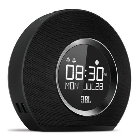
Summary of Contents for JBL Horizon
-
Page 1: Table Of Contents
Service Manual HORIZON Bluetooth clock radio with USB charging and ambient light CONTENTS Safety Information Schematics Diagram Layout Diagram Quick Start Guide Mechanical Exploded View Software Version Check & Upgrade Process Packaging Exploded View Dismantling Instructions Packaging Parts List IC Pins Voltage Mech. -
Page 2: Safety Information
BDS 270 / BDS 570 harman/kardon Important Safety Instructions 1. Read these instructions. CAUTION 2. Keep these instructions. 3. Heed all warnings. RISK OF ELECTRIC SHOCK. DO NOT OPEN. 4. Follow all instructions. 5. Do not use this apparatus near water. 6. - Page 3 Some semiconductor (solid state) devices can be damaged easily by static electricity. Such components commonly are called Electrostatically Sensitive (ES) Devices. Examples of typical ES devices are integrated circuits and some field effect transistors and semiconductor "chip" components. The following techniques should be used to help reduce the incidence of component damage caused by static electricity. 1.
- Page 4 SAFETY PRECAUTIONS The following check should be performed for the continued protection of the customer and service technician. LEAKAGE CURRENT CHECK Measure leakage current to a known earth ground (water pipe, conduit, etc.) by connecting a leakage current tester between the earth ground and all exposed metal parts of the appliance (input/output terminals, screwheads, metal overlays, control shaft, etc.).
-
Page 5: Quick Start Guide
QUILK START GUIDE & SPECIFICATIONS... - Page 6 QUILK START GUIDE & SPECIFICATIONS SPECIFICATIONS...
-
Page 7: Software Version Check
Software Version Check & Software Upgrade Process, and so on Item Operation Description Duration i s r i t a > VOL+ & Bluetooth VOL- & Bluetooth i t a > VOL+ & FM i t a > VOL- & FM >... -
Page 8: Dismantling Instructions
DISMANTLING DIAGRAM Tools List Item Tools Remark The head of The head of screw driver The head of The head of screw driver The head of screw driver Slotted screwdriver Screw driver... - Page 9 DISMANTLING DIAGRAM 3.Remove8pcsscrewsusing 1.Rotateaslottedscrewdriverina 2. Removethelogoplateand screwdriver2.0 counterclockwisedirection,then siliconepart moveupthelogoplate. 4. PutofftheLEDcover...
- Page 10 DISMANTLING DIAGRAM 5. RemoveDSTbuttonandrotate15- 7. Removethemainsiliconepart 6. Afterremovebatterycoverand 30° forBatterycovercounterclockwise DSTbutton onthebottomusingthetool. th b tt th t 9.Removethegrille&siliconecaseas 10. Takeoutthesiliconecaseofmain 8. Disassemblethesiliconecaseas abovepicture setafterremovinggrille. above picture abovepicture...
- Page 11 DISMANTLING DIAGRAM 13. Disassemble2pcsscrewsand 11. Disassemble4pcsscrewsonone 12. Disassemble4pcsscrewson removeUSBcover. sideofSNOOZEbracket. anothersideofSNOOZEbracket. 14. Remove4pcsscrewsforSETbutton 15.Remove2pcsscrewsforUSBboard 16.Remove1pcscrewsofINPUT Board.
- Page 12 DISMANTLING DIAGRAM 19. Splitintothefrontandtherear 17. Disassemble9pcsscrews 18. Removeallthecablesasabove parts. 20. Remove4pcsscrewsonmain 21. PulloutthecablesonPos.No. 22. Disassemble11pcsscrewsofLED board CN9/CN25/CN19/CN24/CN16/CN21 Board.
-
Page 13: Ic Pins Voltage
HORIZON VOLTAGE ON IC PINS ASM32 M016GA 0.31 1.95 3.31 0.669 1~1.5 0.9~1.2 1.7~2 2.8~3.2 3.2 1.56 1.47 2.25 2.25 2.25 2.25 2.25 2.25 2.25 2.25 2.0~2.3 4.94 0.72~0.761.5~1.72 1.4~1.9 HT1621B 1.84 3.26 3.28 3.31 2.9~0.4 3.3-0 0-3.3 2.68 2.34 3.27... -
Page 14: Set Block Diagram
SET BLOCK DIAGRAM ANALOG MUX AUX IN ADC AKM5358A HC4052 TAS5709 AUDIO SN74LV1G04 DSP+AMPLIFIER BT MODULE FM AP420 (SI4702) BM830 12.288MHz 32.768KHz BT2301 LED LIGHT AUDIO DETECT LCD DRIVER MCU M016GA LM358 HT1621 B LCD DISPLAY KEYPAD PCF85163NC 8MHz USB CHARGER BUTTON BATTERY 5V/1A CLOCK... -
Page 15: Set Wiring Diagram
SET WIRING DIAGRAM... -
Page 16: Schematics Diagram
SCHEMATIC DIAGRAM - KEY & MAIN BOARD (PART 1) R120 [1,2] FM_ANT R128 R129 CE13 R114 R107 82nH 100P 100U/16mini 100P C118 AP420 R143 2.7PF C130 C125 LOUT ESD2 FM_L 74HC4052 5.6P 5.6P GND2 ROUT FM_R R144 GND2 GND1 12 OLIN C119 FB1K FM_L... - Page 17 SCHEMATIC DIAGRAM - USB & MAIN BOARD (PART 2) R162 R169 BTANT C100 1N4148 ANT1 SPK_LP C124 A8550 SPK_LN R159 SPK_RP R165 SPK_RN [1,2] 15UH C128 C117 R170 R161 C143 C144 470U/16mini R190 9014 C135 AVDD_3.3V AVDD R189 PGND_AB C142 C141 BM830 FAULT...
- Page 18 SCHEMATIC DIAGRAM - LCD BOARD R217 R216 R215 SEG7 SEG8 DATA1 SEG6 SEG9 HT1621B SEG5 SEG10 C154 C153 SEG4 SEG11 ESD20 12/1206 R218 LCD_5V SEG3 SEG12 LED+ SEG2 SEG13 BT2301 BACKLIGHT_EN LED- BK_EN SEG1 SEG14 GRES R221 SEG0 SEG15 3.3K SEG16 R213 SEG17...
-
Page 19: Layout Diagram
LAYOUT DIAGRAM - MAIN BOARD... - Page 20 LAYOUT DIAGRAM - LCD BOARD...
- Page 21 LAYOUT DIAGRAM - KEY BOARD LAYOUT DIAGRAM - USB BOARD...
- Page 22 LAYOUT DIAGRAM - LAMP/SNOOZE/INPUT/BATTERY BOARD...
-
Page 23: Mechanical Exploded View
SET MECHANICAL EXPLODED VIEW... -
Page 24: Packaging Exploded View
Packaging Exploded View Adaptor Insert M FM Antenna RETAIL BOX LDPE BAG EPE Bag MAIN UNIT INSERT A INSERT B Insert L Insert R 4 RETAIL BOXES CARTON BOX Safety Sheet... -
Page 25: Packaging Parts List
WHITE VERSION 412301100109 Power adaptor with Exchangeable plugs 88-280V 13V/2.2A L1.5M DC4.0*1.7*9.5mm US/JP GIP ,080-2986 l i a 462510483009 Quick Start Guide 128g C2S, 4colors, 4 folded,080-2997 462510483019 Safety Sheet L150*W80mm 4P/100g, 80P/70g,080-2556-D 412301100209 Power adaptor with Exchangeable plugs 88-280V 13V/2.2A L1.5M DC4.0*1.7*9.5mm EU/UK GIP ,080-2988 l i a EMEA... - Page 26 Generic Parts...
-
Page 27: Mech. & Elec. Parts List
USB BOARD 993104830509 USB BOARD WHT 993104830519 USB BOARD BLK 311048306009 INPUT BOARD 993104830609 INPUT BOARD 311048307009 Horizon LCD BOARD 993104830719 Horizon LCD BOARD 403900050109 IC HT1621B SSOP48 U22,U24 411000260109 LCD 56PIN 4.5V 84*51.5MM WITH BACKLIGHT 993104830819 EU BATTERY BOARD WHT... - Page 28 461126000219 CABLE 2P L=60MM 28AWG CN23 331104830109 GRILL ASS'Y(Fabric+Bracket+Chrome Rim) BLK 53+54+55 331104830119 GRILL ASS'Y(Fabric+Bracket+Chrome Rim) BLK 53+54+55 331104830139 GRILL ASS'Y(Fabric+Bracket+Chrome Rim) WHT 53+54+55 24104830301049 FRONT HOUSING 24104830101049 PORT LOWER 24104831601049 PORT UPPER 24104831401049 SNOOZE BUTTON 24104831501049 SNOOZE BUTTON BRACKET 25104830201009 REAR HOUSING 420201460109...
-
Page 29: Revision List
Revision List V1.0 2014-11 Initial release V1.1 2014-12 Remove SW/FW upgrade process and add Parts List V1.2 2015-09 Parts List Updated...


Need help?
Do you have a question about the Horizon and is the answer not in the manual?
Questions and answers