Table of Contents
Advertisement
Quick Links
Advertisement
Table of Contents

Related Manuals for PROVA A9+


Summary of Contents for PROVA A9+
- Page 1 AC/DC TRMS CLAMP METER USERS MANUAL PROVA INSTRUMENTS INC.
- Page 2 25/09/2019 Version: 20190925 Specifications are subjected to change without notice. Copyright © 2019 Prova Instruments Inc., All rights reserved.
- Page 3 EN 61010-2-032 CAT III 600V CAT IV 300V Pollution Degree 2 SYMBOLS showed on the clamp meter or in this manual: Caution, risk of danger. Refer to accompanying documents Caution, risk of electric shock. Double Insulation Application around and removal from HAZARDOUS LIVE conductors is permitted.
- Page 4 Overvoltage Category I (CAT I): Equipment for connection to circuits in which measures are taken to limit the transient overvoltages to an appropriat e low level. Overvoltage Category II (CAT II): Energy-consuming equipment to be supplied from the fixed installation. Overvoltage Category III (CAT III): Equipment in fixed installations, distribution boards, and circuit breakers.
-
Page 5: Table Of Contents
TABLE OF CONTENTS I. Features ........................2 II. Panel Description ....................3 III. Operation Instructions ..................6 3.1 AC/DC Current Measurements ..............6 3.2 Frequency (Hz) Measurement ..............7 3..3 Relative (Δ) Reading Measurements ............7 3.4 Data Hold of the LCD Reading ..............8 3.5 In-Rush Current (INR) Measurement ............ -
Page 6: Features
I. Features 1. Min. resolution AC/DC 1mA and max. current range of AC/DC 1000A 2. Super wide range AC/DC 4.000A/40.00A/400.0A/1000A 3. Best accuracy ±1.5%±3dgts for all ranges 4. Accurate and solid AC/DC mini pocket-size clamp meter 5. True RMS measurement Δ... -
Page 7: Panel Description
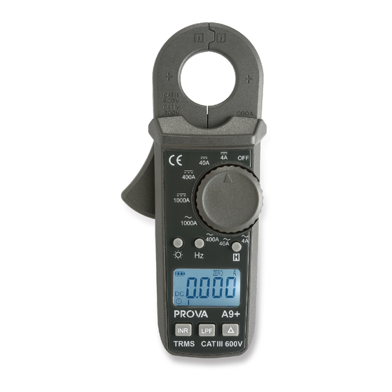
II. Panel Description 1. Moving and Stationary Jaws This is used to pick up current signal. To measure DC/AC current, conductor must be enclosed by the jaw. 2. Moving Jaw Trigger This is used to open the jaw. 3. Rotary Switch This is the on/off switch and used to select the function user desired, such as DCA, or ACA. - Page 8 release it. 5. Frequency (Hz) Button This button is used to measure frequency of ACA current in the ACA function. 6. Backlight Button Press this button to turn the backlight on. Press it again to turn the backlight off. The backlight will turn itself off automatically in 5 minutes. 7.
- Page 9 A clock symbol is displayed to indicate auto power off is enabled.
-
Page 10: Operation Instructions
III. Operation Instructions 3.1 AC/DC Current Measurements 3.1.1 DC Current a. Set the rotary switch at appropriate DC range. Δ b. Push the zero ( ) button to adjust the reading to zero. The symbol “ZERO” is displayed on LCD. c. -
Page 11: Frequency (Hz) Measurement
a. Set the rotary switch at appropriate AC range. b. Press the trigger to open the jaw and fully enclose the conductor to be measured. No air gap is allowed between the two half jaws. c. Read the ACA value from the LCD display. button is pressed in the ACA function, the symbol of “... -
Page 12: Data Hold Of The Lcd Reading
Note: If the (ZEROed value +relative measured value) is greater than the range (4000 counts), the meter will still show OL under ZERO function. Namely, if the absolute measured value is greater than 4000 counts, LCD shows OL. 3.4 Data Hold of the LCD Reading Press the HOLD button, then the reading shall be held and kept on LCD. -
Page 13: Specifications
IV. Specifications (23 ℃ ±5 ℃, Accuracy is indicated as % of reading, and the conductor is placed at the center of jaws) DC Current (% of reading): Range Resolution Accuracy Overload Protection 10mA ±1.5%±3dgts 400A 100mA DC 1000A 0-900A(1000A) 900-1000A(1000A) ±2.0%±3dgts AC Current (True RMS, Crest Factor ≦... - Page 14 AC Low Pass Filter (LPF, Cut-off frequency (-3db) 1 KHz (approx.)) Range Resolution Accuracy (of reading, 50/60Hz) 0.001 0.01 3%±5dgts 400A 0 – 900A (1000A) 900-1000A(1000A) 4%±5dgts Indoor Use 0.98” / 25mm max. (approx.) Conductor Size: Battery Type: two 1.5V LR03 AAA size Display: 3 3/4 LCD with 20 segments Bar-graph Range Selection:...
-
Page 15: Battery Replacement
V. Battery Replacement When the low battery symbol is displayed on the LCD, replace the old batteries with two new batteries. A. Turn the power off. B. Remove the screw of the battery compartment. C. Lift and remove the battery compartment. D.
Need help?
Do you have a question about the A9+ and is the answer not in the manual?
Questions and answers