
Related Manuals for Nokia IP710 Series


Summary of Contents for Nokia IP710 Series
- Page 1 All manuals and user guides at all-guides.com IP700 Series Installation Guide Part Number: N450436003 Rev B April 2004...
- Page 2 IMPORTANT NOTE TO USERS This software and hardware is provided by Nokia Corporation as is and any express or implied warranties, including, but not limited to, implied warranties of merchantability and fitness for a particular purpose are disclaimed. In no event shall Nokia, or its affiliates, subsidiaries or suppliers be liable for any direct, indirect, incidental, special, exemplary, or consequential damages (including, but not limited to, procurement of substitute goods or services;...
- Page 3 Tel: 1-877-997-9199 313 Fairchild Drive Outside USA and Canada: +1 512-437-7089 Mountain View, CA 94043-2215 e-mail: info.ipnetworking_americas@nokia.com Europe Nokia House, Summit Avenue Tel: 00800 5543 1816 or 1+44 (0) 8700 555 777 Southwood, Farnborough e-mail: info.ipnetworking_emea@nokia.com Hampshire GU14 ONG U.K Asia-Pacific...
- Page 4 All manuals and user guides at all-guides.com...
-
Page 5: Table Of Contents
......11 About Nokia IP700 Series Network Security Platforms ....12 IP700 Series Documentation. - Page 6 Connecting to Gigabit Ethernet Devices ..104 Connecting to a Modem ..... . 107 Installing the Nokia Encryption Accelerator CHAPTER 6 Card .
- Page 7 All manuals and user guides at all-guides.com Contents Protecting the Boot Manager with a Password ..130 Installing Boot Manager ..... 131 Upgrading Boot Manager .
- Page 8 All manuals and user guides at all-guides.com Contents General Public Licensed Software APPENDIX C ..167 GNU GENERAL PUBLIC LICENSE ... 168 Warranty and Software License APPENDIX D .
- Page 9 8-pin female (host) ..........98 Typical Nokia T1 Network Interface Card Front Panel Details... . . 100 Output Connector for the T1 Cable .
- Page 10 All manuals and user guides at all-guides.com Figures IP700 Series Installation Guide...
-
Page 11: About This Guide
All manuals and user guides at all-guides.com About This Guide This preface provides the following information: • About Nokia IP700 Series Network Security Platforms (see page 12) • IP700 Series Documentation (see page 13) • Structure of This Guide (see page 14) •... -
Page 12: About Nokia Ip700 Series
• OS and application upgrades and licensing • configuration-file backup and restore • application installation Nokia Horizon Manager allows you to manage all your NSPs and perform image management actions on multiple platforms simultaneously. IP700 Series Installation Guide... -
Page 13: Ip700 Series Documentation
All manuals and user guides at all-guides.com IP700 Series Documentation IP700 Series Documentation The Nokia documentation set consists of Release Notes for the Nokia software release you are running, the IP700 Series Installation Guide (this document), a Voyager inline help feature, and the Voyager Reference Guide (online). -
Page 14: Structure Of This Guide
CHAPTER 5, Connecting to the Network explains how to connect to and use each of the supported network interface cards. • CHAPTER 6, Installing the Nokia Encryption Accelerator Card explains how to install and enable the accelerator card. • CHAPTER 7, Using the Boot Manager explains how to use the boot manager, which is part of the built-in IPSO software. - Page 15 APPENDIX C, General Public Licensed Software provides information about publicly licensed software that comes with the appliance. • APPENDIX D, Warranty and Software License contains Nokia warranty and software license information. • APPENDIX E, Glossary of Abbreviations provides definitions to acronyms and initialisms used throughout the guide.
-
Page 16: Conventions Used In This Guide
All manuals and user guides at all-guides.com About This Guide Conventions Used in This Guide This section describes the conventions used in text, examples, and graphics. Typeface/ Example Meaning Italic • Link, data entry location, Click the Interfaces link. menu name, option name, Turn Internal Clock off. - Page 17 All manuals and user guides at all-guides.com Conventions Used in This Guide WARNING: Shows critical information that, if ignored, could cause injuries to you or to other people, damage to your equipment, or a potential security breach. Caution: Addresses actions that cause damage to equipment, compromise the system, or would cause data loss.
- Page 18 All manuals and user guides at all-guides.com About This Guide IP700 Series Installation Guide...
-
Page 19: Chapter 1 Overview
All manuals and user guides at all-guides.com Overview CHAPTER 1 About the IP700 Series Platform The Nokia IP700 Series platform combines the power of IPSO software with your choice of applications. Each IP700 Series appliance consists of components in three primary categories: •... -
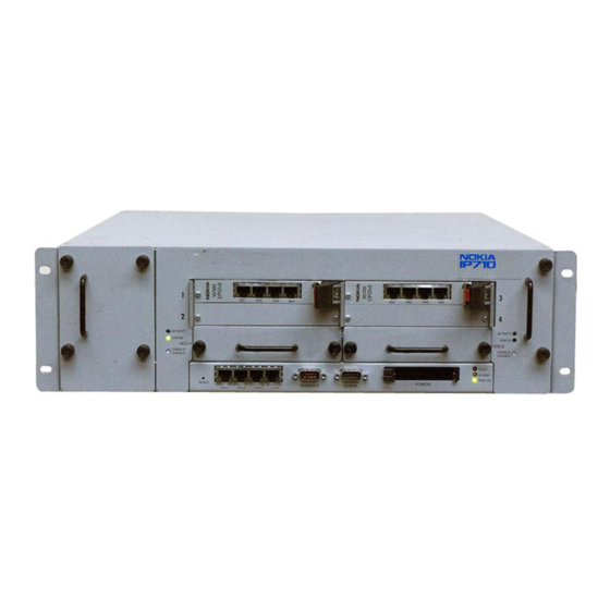
Page 20: Component Locations (Sample Configuration)
All manuals and user guides at all-guides.com Chapter 1: Overview The following diagram shows component locations in a sample configuration. Component Locations (Sample Configuration) Four-port Ethernet Front View Fan tray (10/100 Mbps) card T1 Card Hard-Disk Drive 00082 PCMCIA Slot Four-port Ethernet Modem port (10/100 Mbps) - Page 21 The IP700 Series appliance also includes a PCMCIA slot that supports PCMCIA modems. Nokia products support only Nokia cards. The Nokia Customer NOTE: Support Department supports Nokia cards purchased either from Nokia Inc. or approved resellers. Contact Nokia for sales or reseller information. IP700 Series Installation Guide...
-
Page 22: Site Requirements
All manuals and user guides at all-guides.com Chapter 1: Overview Site Requirements Before you install the IP700 Series appliance, ensure that your computer room or wiring closet conforms to the environmental specifications listed in APPENDIX A, Technical Specifications. Using controls, making adjustments in performance, or WARNING: following procedures that are not described in this document can result in hazardous radiation exposure. -
Page 23: Chapter 2 Installing The Ip700 Series Appliance
Installing the IP700 Series Appliance CHAPTER 2 This chapter describes how to install the Nokia IP700 Series appliance, configure the system, connect it to your network, and monitor it. See these topics for instructions to perform the tasks necessary for installing or maintaining your appliance: •... -
Page 24: Using Dhcp To Configure The Appliance
All manuals and user guides at all-guides.com Chapter 2: Installing the IP700 Series Appliance IPSO Version Requirements To run an IP710 appliance, you must use IPSO v3.5 or higher. To run an IP740 appliance, you must use IPSO v3.4 or higher. Using DHCP to Configure the Appliance You can use the built-in dynamic host configuration protocol (DHCP) client to configure the system instead of using a console connection. - Page 25 The minimum IP address lease required is one year. Either the DHCP server must be on the same network as your NOTE: Nokia IP700 Series appliance, or DHCP/BOOTP relay must be configured on the intermediate routers. Following is an example of relevant DHCP configuration information: ddns-update-style ad-hoc;...
- Page 26 From a computer on the same network, ping the IP address that you configured the DHCP server to provide to the IP700 Series appliance. When you receive replies from ping, you can use Nokia Network Voyager to connect to the system.
-
Page 27: Using The Console Connection To Configure The Appliance
All manuals and user guides at all-guides.com Using the Console Connection to Configure the Appliance Using the Console Connection to Configure the Appliance If you use a console connection (a direct serial connection to the console port) to configure your IP700 Series appliance, you are prompted for the appropriate configuration settings the first time you turn it on. -
Page 28: Connecting Power And Turning The Power On
All manuals and user guides at all-guides.com Chapter 2: Installing the IP700 Series Appliance Connecting Power and Turning the Power On The IP700 Series appliance power supplies automatically detect NOTE: the input voltage (115VAC [90 to 132] or 220VAC [180 to 264]) and configure themselves appropriately. - Page 29 If the power supply fans are not running, check the power supply cord to make sure it is properly connected. If the fans are still not running after this check, contact technical support. See “Nokia Contact Information” on page 3 for more information.
-
Page 30: Connecting To The Console
All manuals and user guides at all-guides.com Chapter 2: Installing the IP700 Series Appliance Connecting to the Console The IP700 Series appliance requires a serial console connection for initial configuration and occasional maintenance (cable included). The console port on the IP700 Series appliance provides the following: •... -
Page 31: Component Location
All manuals and user guides at all-guides.com Connecting to the Console If you connect the console port to a data communications NOTE: equipment (DCE) device, use a straight-through cable. Component Location 00082 Console port IP700 Series Installation Guide... - Page 32 All manuals and user guides at all-guides.com Chapter 2: Installing the IP700 Series Appliance The following figure provides pin assignment information for console and modem-port connections. Input/ Pin# Assignment Output Input Input Output Output 700001 Input Output Input Output Connect the other end of the cable to the VT100 console, computer, or laptop running a terminal emulation program.
-
Page 33: Monitoring The Appliance
All manuals and user guides at all-guides.com Monitoring the Appliance Do not type anything at the prompt yet. CHAPTER 4, Configuring and Monitoring the IP700 Series Appliance contains software configuration instructions. If the hostname message does not appear on the console, check NOTE: the console port and console display connections to ensure that the serial cable is completely plugged in at both ends. -
Page 34: Typical Four-Port Ethernet Network Interface Card Front Panel Details
E1 cards See “Typical E1 Network Interface Card Front Panel Details” on page 96. T1 cards See “Typical Nokia T1 Network Interface Card Front Panel Details” on page 100. ATM cards See “Typical ATM Network Interface Card Front Panel Details” on page 102. -
Page 35: Chapter 3 Installing, Monitoring, And Replacing Components
All manuals and user guides at all-guides.com Installing, Monitoring, and Replacing CHAPTER 3 Components Your IP700 Series appliance might come with its network interface cards (NICs) preinstalled. However, if you need to add or replace a NIC, this chapter provides instructions on how to do so, including tasks related to installing, monitoring, and replacing components associated with your IP700 Series appliance: •... -
Page 36: Network Interface Card Preinstallation
All manuals and user guides at all-guides.com Chapter 3: Installing, Monitoring, and Replacing Components Caution: Protect your IP700 Series appliance and other electronic equipment from static discharge by making sure you are properly grounded before touching any electronic components. When you are handling a card, take care not to damage the Caution: EMI shield on the top edge of the face plate. - Page 37 All manuals and user guides at all-guides.com Network Interface Card Preinstallation Considerations In the IP740, each cPCI bus is independently capable of running at 66 Mhz, but it can run at 33 Mhz under certain circumstances. Accordingly, you can use any compatible card in any slot, but certain configurations might not provide optimum performance.
- Page 38 All manuals and user guides at all-guides.com Chapter 3: Installing, Monitoring, and Replacing Components Operating Speeds of Network Interface Cards Used With the IP700 Series Platforms The following 66-Mhz and 33-Mhz cards are available from Nokia. Network Interface Operating Speed of Operating Speed of...
- Page 39 All manuals and user guides at all-guides.com Network Interface Card Preinstallation Considerations Preferred Slot Assignments for 33-Mhz Cards If you install a 33-Mhz card in one of the IP740 appliance slots, that bus runs at 33 Mhz. Therefore, if possible, confine your 33-Mhz cards to one bus.
-
Page 40: Connecting To Gigabit Ethernet Nics For High Availability With A Dmz Port
All manuals and user guides at all-guides.com Chapter 3: Installing, Monitoring, and Replacing Components To use this type of configuration, install four gigabit Ethernet NICs and connect to the NIC interfaces as the following figure shows. Connecting to Gigabit Ethernet NICs for High Availability With a DMZ Port Traffic #1 Port Synchronization Port Traffic #2 Port... -
Page 41: High Availability With A Dmz Environment
All manuals and user guides at all-guides.com Network Interface Card Preinstallation Considerations The following figure shows an example of a network configured for high availability using VRRP including a DMZ. High Availability With a DMZ Environment Switch Switch E-mail/ Network Web Server Management IP700... - Page 42 All manuals and user guides at all-guides.com Chapter 3: Installing, Monitoring, and Replacing Components IP740 Example Configurations Hot Plugging a 66-Mhz Card in the IP740 If you hot plug a 66-Mhz card, the card is automatically brought online. If a 33-Mhz card is already on that bus, the new card also runs at 33 Mhz. If no 33-Mhz cards are on the bus, but the Slot Status Voyager page indicates that cards on the bus are running at 33 Mhz, a 33-Mhz card was previously present on that bus.
-
Page 43: Installing A New Network Interface Card
All manuals and user guides at all-guides.com Installing a New Network Interface Card Installing a New Network Interface Card The following procedure applies to all network interface cards: See “Network Interface Card Preinstallation Considerations” on page 36. Use a screwdriver to remove the retaining screws that hold the blank panel in place. - Page 44 All manuals and user guides at all-guides.com Chapter 3: Installing, Monitoring, and Replacing Components Insert the new card. Push it gently into place. Take care to make sure that the card edge is completely seated into the connector inside the IP700 Series appliance.
-
Page 45: Monitoring Network Interface Cards
For information about the LEDs, see “Typical E1 Network Interface Card Front Panel Details” on page 96 For information about the LEDs, see “Typical Nokia T1 Network Interface Card Front Panel Details” on page 100 For information about the LEDs, see “Typical ATM Network Interface Card Front Panel... -
Page 46: Removing A Network Interface Card
All manuals and user guides at all-guides.com Chapter 3: Installing, Monitoring, and Replacing Components Removing a Network Interface Card The following procedure applies to all network interface cards: Use Voyager to perform the following: Deactivate all of the logical interfaces on the card. Deactivate all of the physical interfaces on the card. - Page 47 All manuals and user guides at all-guides.com Removing a Network Interface Card Gently pull the card forward from the card slot. If the card has an ejector, use it to assist you in removing the card from the slot. 00084 IP700 Series Installation Guide...
- Page 48 All manuals and user guides at all-guides.com Chapter 3: Installing, Monitoring, and Replacing Components Cover the empty slot with a blank panel and screw the retaining screws into place. The blank panel goes in only one way, with the EMI fingers up. NOTE: 00096 IP700 Series Installation Guide...
-
Page 49: Replacing A Network Interface Card
All manuals and user guides at all-guides.com Replacing a Network Interface Card Replacing a Network Interface Card You can replace a network interface card with the following card types: • A different type (for example, replace an Ethernet card with a T1 card). - Page 50 All manuals and user guides at all-guides.com Chapter 3: Installing, Monitoring, and Replacing Components Gently pull the card forward from the card slot. If the card has an ejector, use it to assist you in removing the card from the slot. 00084 IP700 Series Installation Guide...
- Page 51 All manuals and user guides at all-guides.com Replacing a Network Interface Card Insert the new card. Push it gently into place. Make sure that the card edge is completely seated into the connector inside the IP700 Series appliance. If the card has an ejector, you can use it to assist in the final seating of the card.
-
Page 52: Installing A Pcmcia Modem
Voyager Reference Guide. To use a modem with the IP700 Series appliance, use the following procedures: If the modem is not factory installed, insert the Nokia-approved PCMCIA modem into either the top or bottom PCMCIA slot until the modem clicks into place. -
Page 53: Monitoring And Replacing A Hard-Disk Drive Unit
All manuals and user guides at all-guides.com Monitoring and Replacing a Hard-Disk Drive Unit Monitoring and Replacing a Hard-Disk Drive Unit The IP700 Series appliance includes one disk drive unit, which you can remove and replace. The following figure shows a hard-disk drive unit. The status LEDs and hot swap switch are indicated by the gray circle. - Page 54 All manuals and user guides at all-guides.com Chapter 3: Installing, Monitoring, and Replacing Components Monitoring a Hard-Disk Drive Unit The disk drive unit has two LEDs associated with it, one for disk activity and one for disk status, as shown in the preceding figure. These LEDs are located to the left of the unit.
-
Page 55: Power Switch Locations
All manuals and user guides at all-guides.com Monitoring and Replacing a Hard-Disk Drive Unit Removing a Hard-Disk Drive Unit Caution: Failing to use the following procedure when removing the hard-disk drive unit can result in damage to the unit or data loss. To perform an orderly shut down of the operating system, follow these steps: On the Voyager home page for the appliance, click... - Page 56 All manuals and user guides at all-guides.com Chapter 3: Installing, Monitoring, and Replacing Components Use a screwdriver to remove the retaining screw holding the hard- disk drive unit 00085 Gently pull the hard disk-drive unit forward from the card slot and remove the hard-disk drive unit 00100 IP700 Series Installation Guide...
- Page 57 Before you can replace a hard-disk drive unit, you must load the new unit with the appropriate software. For further information, contact the appropriate Nokia customer support site as listed in “Nokia Contact Information” on page 3. Make sure you replace the new disk drive in slot A, as the NOTE: following figures show.
- Page 58 All manuals and user guides at all-guides.com Chapter 3: Installing, Monitoring, and Replacing Components Screw the retaining screws into place. 00085 Switch on the IP700 Series appliance. IP700 Series Installation Guide...
-
Page 59: Replacing The Fan Tray
All manuals and user guides at all-guides.com Replacing the Fan Tray Replacing the Fan Tray You can change the fan tray without turning off the IP700 Series appliance. Components inside the chassis can overheat if they are not Caution: cooled for even short periods of time. If you keep the power to the IP700 Series appliance on, do not allow the fan tray to remain out of the chassis for any longer than is necessary. - Page 60 All manuals and user guides at all-guides.com Chapter 3: Installing, Monitoring, and Replacing Components Pull the fan tray forward to remove it from the chassis. 00088 Slide the new fan tray into the chassis. 00088 Screw in the retaining screws. IP700 Series Installation Guide...
-
Page 61: Monitoring And Replacing A Power Supply
All manuals and user guides at all-guides.com Monitoring and Replacing a Power Supply Monitoring and Replacing a Power Supply If the IP700 Series appliance contains two power supplies, you can replace one of the power supplies without turning off the IP700 Series appliance. - Page 62 All manuals and user guides at all-guides.com Chapter 3: Installing, Monitoring, and Replacing Components Deactivate the power supply you are replacing by turning off the switch on the back of the power supply. 00099 Unplug the power cord from the power supply. Confirm that the cooling-fan blade assembly is no longer turning.
- Page 63 All manuals and user guides at all-guides.com Monitoring and Replacing a Power Supply Grasp the handle and firmly pull the power supply toward you. 00087 Slide the new power supply into place. 00087 Replace the retaining screws and screw them into place. Reconnect the power cord.
-
Page 64: Upgrading The Memory
Upgrading the Memory This section explains how to upgrade the memory to 1 GB from 512 MB by using either one or two Nokia-approved memory upgrade kits. Each kit includes two 256-MB DIMMs, and the number you use depends on the number and capacity of the DIMMs currently installed in your appliance. - Page 65 Physical access to the appliance • A Phillips-head screwdriver • The appropriate number of Nokia memory upgrade kits, each of which includes two 256-MB Dual Inline Memory Modules (DIMMs) • Access to the appliance through Voyager or Lynx Accessing DIMM Sockets...
- Page 66 All manuals and user guides at all-guides.com Chapter 3: Installing, Monitoring, and Replacing Components Turn off both power switches on the rear of the appliance and remove both power cords from the power supplies. Confirm that the two cooling-fan blade assemblies are no longer turning.
- Page 67 All manuals and user guides at all-guides.com Upgrading the Memory Accessing and Removing the Existing DIMMs To install the memory upgrade kit, use the following procedure. Remove the two power supplies as follows (removing the power supplies allows you to disengage the motherboard chassis assembly from its connectors and prevents the front panel from being damaged as the chassis assembly is pulled out).
- Page 68 All manuals and user guides at all-guides.com Chapter 3: Installing, Monitoring, and Replacing Components Grasp each power-supply handle and firmly pull each power supply toward you. 00087 Loosen the four front-panel thumbscrews indicated in the following figure. 00085 IP700 Series Installation Guide...
- Page 69 All manuals and user guides at all-guides.com Upgrading the Memory Slide the chassis assembly forward to expose the motherboard components, as the following figure shows. 00171 IP700 Series Installation Guide...
-
Page 70: Dimm Socket Locations
All manuals and user guides at all-guides.com Chapter 3: Installing, Monitoring, and Replacing Components The DIMM sockets are located at the right of the IP700 mother board, as you look at the appliance from the front, as the following figure shows. DIMM Socket Locations Front of Motherboard Installing the New DIMMs in the IP700 Series Appliance... - Page 71 All manuals and user guides at all-guides.com Upgrading the Memory For each DIMM you remove from your IP700 series appliance, perform the following procedure. NOTE: The figures show these steps for the DIMM socket closest to the front of the appliance. If your appliance has four 128-MB DIMMs, remove the four NOTE: 128-MB DIMMs and install a 256-MB DIMM into each of the four...
-
Page 72: Pressing Dimms Into Dimm Sockets
All manuals and user guides at all-guides.com Chapter 3: Installing, Monitoring, and Replacing Components Press the new DIMM into the socket until it clicks into place, as the following figure shows. The top of the DIMM is smooth. The bottom edge of the DIMM has two keyed sets of contacts, which mate with two key slots on the socket. - Page 73 All manuals and user guides at all-guides.com Upgrading the Memory Slide the two power supplies into place. 00087 Replace the retaining screws and screw them into place. Reattach the power cords. Turn on the power. The appliance automatically recognizes the new memory configuration.
- Page 74 All manuals and user guides at all-guides.com Chapter 3: Installing, Monitoring, and Replacing Components IP700 Series Installation Guide...
-
Page 75: Configuring And Monitoring The Ip700 Series Appliance
All manuals and user guides at all-guides.com Configuring and Monitoring the CHAPTER 4 IP700 Series Appliance System startup consists of the following steps: • Entering the Hostname (see page 76) • Entering the Passwords (see page 76) • Entering the Browser Type (see page 76) •... -
Page 76: Entering The Hostname
System startup prompts you to select the browser type you plan to use to complete your configuration, as follows: You can configure your Nokia system in two ways. 1) configure an interface and use our Web-based Voyager via remote browser... - Page 77 All manuals and user guides at all-guides.com Entering the Browser Type Select option if the IP700 Series appliance is connected to a network and you have access to a host machine that can run Netscape Navigator, version 4.0 or later, or Microsoft Internet Explorer, version 4.0 or later. You can also use a laptop connected to the Ethernet interface with a local address.
-
Page 78: Entering Initial Interface Information
All manuals and user guides at all-guides.com Chapter 4: Configuring and Monitoring the IP700 Series Appliance Entering Initial Interface Information Select an interface you want to use to access the IP700 Series appliance from the host that runs your browser. System startup searches for all of the connected interfaces and displays a list of the physical IDs that it finds. - Page 79 All manuals and user guides at all-guides.com Entering Initial Interface Information Enter the IP address for the interface you selected in step 1. If you selected an Ethernet, fiber distributed data interface (FDDI) interface, enter the IP address and mask length (in bits). For example: 192.0.0.1/25 If you selected an asynchronous transfer mode (ATM) or serial interface, enter the local and remote IP addresses.
- Page 80 All manuals and user guides at all-guides.com Chapter 4: Configuring and Monitoring the IP700 Series Appliance If you selected a V.35 or X.21 serial interface, enter: • The appropriate serial datalink (Cisco HDLC, PPP, or frame relay) • Serial datalink configuration parameters, just as you do if you selected a serial interface If you selected a serial interface, enter the configuration for the selected serial datalink protocol.
-
Page 81: Confirming New System Setup Summary
All manuals and user guides at all-guides.com Confirming New System Setup Summary Confirming New System Setup Summary Confirm the setup summary (type Y), or type N to make different selections. Selecting Y allows you to use the quit option (4 in this example) to exit system startup. -
Page 82: Voyager Reference Access Points Example
Voyager Reference Guide The Voyager Reference Guide is the reference source for Voyager. To access this source, click You can also access the Voyager Reference Guide at the Nokia support site ( ) or on the CD that was delivered with your https://support.nokia.com... - Page 83 All manuals and user guides at all-guides.com Using Voyager to Configure the Network Interfaces Voyager Inline Help You can access inline help when you are using Voyager. Inline help is the context-sensitive information source for Voyager. To enable inline help for a specific subject, click the button next to the subject.
- Page 84 All manuals and user guides at all-guides.com Chapter 4: Configuring and Monitoring the IP700 Series Appliance Using Voyager to Monitor the IP700 Series Appliance After you install and configure your IP700 Series appliance, you can use Voyager to monitor its operation. Click from the Voyager home ONITOR page to access the monitoring functions.
-
Page 85: Connecting To The Network
All manuals and user guides at all-guides.com Connecting to the Network CHAPTER 5 This chapter describes how to connect your IP700 Series appliance to other network devices through network interface cards and how to maintain those and other appliance components. These tasks are as follows: •... -
Page 86: Connecting To Ethernet Devices
IP700 Series appliances. Most NIC cards developed for earlier Nokia IP platforms are cPCI v1 compatible and do not work in the IP740. The only exceptions are the gigabit Ethernet card and the newest of the quad ethernet cards. - Page 87 00019 Link LEDs (Green) NOTE: Although Nokia distributes two versions of the quad-port Ethernet cards, only one is compatible with the IP700 Series platform. The connector on the back of the correct quad-port Ethernet card runs IP700 Series Installation Guide...
- Page 88 All manuals and user guides at all-guides.com Chapter 5: Connecting to the Network across the entire width of the card, while the connector on the back of the incompatible quad-port Ethernet card runs only halfway across the width of the card. Hardware Setup When you specify that an Ethernet NIC is to be included with your IP700 Series appliance, the board is installed before the appliance is delivered to...
-
Page 89: Output Connector For The Ethernet Cable
All manuals and user guides at all-guides.com Connecting to Ethernet Devices Cables connecting to any of the Ethernet ports must use a Caution: minimum of 26-AWG wire. In the following figures, the RJ-45 cable output connector is numbered from right to left, with the copper tabs facing up and toward you. Output Connector for the Ethernet Cable Pin# Assignment... -
Page 90: Ethernet Crossover-Cable Pin Connections
All manuals and user guides at all-guides.com Chapter 5: Connecting to the Network Ethernet Crossover-Cable Pin Connections 00017 NOTE: After the power is turned on, the Ethernet link LEDs on both the IP700 Series appliance and on the remote equipment light up to indicate the connection. -
Page 91: Connecting To V.35 Or X.21 Devices
All manuals and user guides at all-guides.com Connecting to V.35 or X.21 Devices Connecting to V.35 or X.21 Devices The IP700 Series appliance supports Nokia-approved, dual-port V.35 and X.21 cards. The cards support the following features: • Line speed to full T1 and E1 •... - Page 92 All manuals and user guides at all-guides.com Chapter 5: Connecting to the Network Hardware Setup When you specify that a V.35 or X.21 NIC is to be included with your IP700 Series appliance, the board is installed before the appliance is delivered to you.
-
Page 93: Output Connector For The V.35 Cable
All manuals and user guides at all-guides.com Connecting to V.35 or X.21 Devices To determine the type of interface (V.35 or X.21), look at the connector on the front panel of the card. The following figures show the physical configuration for each connector type. Output Connector for the V.35 Cable Signal Ground B A Chassis Ground... -
Page 94: Output Connector For The X.21 Cable
All manuals and user guides at all-guides.com Chapter 5: Connecting to the Network Output Connector for the X.21 Cable 1 Protective Ground Transmitted Data (B) 9 2 Transmitted Data (A) Control (B) 10 3 Control (A) Receive Data (B) 11 4 Received Data (A) Indicate (B) 12 5 Indicate (A) -
Page 95: Connecting To E1 (Built-In Csu/Dsu) Devices
All manuals and user guides at all-guides.com Connecting to E1 (Built-in CSU/DSU) Devices Connecting to E1 (Built-in CSU/DSU) Devices The IP700 Series appliance supports Nokia-approved, single-port E1 cards. The card supports the following features: • Direct, high-speed access for network connections over leased lines •... - Page 96 All manuals and user guides at all-guides.com Chapter 5: Connecting to the Network Front Panel Details Typical E1 Network Interface Card Front Panel Details LOS ALARM (Red LED) REMOTE ALARM (Yellow LED) SYNC (Green LED) LOOP (Yellow LED) 00181 E1 cards marked cPCI v2 are the only versions of this card that NOTE: function properly in IP700 Series appliances.
-
Page 97: Output Connector For The E1 Cable
All manuals and user guides at all-guides.com Connecting to E1 (Built-in CSU/DSU) Devices You can order appropriate adapter cables separately. You can order additional cables from a cable vendor of your choice. Caution: Cables connecting to the E1 card must use a minimum of 26- AWG wire. -
Page 98: E1 Crossover Cable Pin Connections
All manuals and user guides at all-guides.com Chapter 5: Connecting to the Network E1 Crossover Cable Pin Connections 8-pin female (host) 00018 IP700 Series Installation Guide... -
Page 99: Connecting To T1 (Built-In Csu/Dsu) Devices
All manuals and user guides at all-guides.com Connecting to T1 (Built-in CSU/DSU) Devices Connecting to T1 (Built-in CSU/DSU) Devices The IP700 Series appliance supports Nokia-approved, single-port T1 cards. The T1 cards provide the following features: • Built-in CSU/DSU for lengthy and short operations •... - Page 100 All manuals and user guides at all-guides.com Chapter 5: Connecting to the Network Front Panel Details Typical Nokia T1 Network Interface Card Front Panel Details LOS ALARM (Red LED) REMOTE ALARM (Yellow LED) SYNC (Green LED) LOOP (Yellow LED) T1 cards marked cPCI v2 are the only versions of this card that NOTE: function properly in IP700 Series appliances.
-
Page 101: Output Connector For The T1 Cable
All manuals and user guides at all-guides.com Connecting to T1 (Built-in CSU/DSU) Devices Cables connecting to the T1 card must use a minimum of 26- Caution: AWG wire. In the following figures, the RJ-48 cable output connector is numbered from right to left, with the copper tabs facing up and toward you. Output Connector for the T1 Cable Pin# Assignment... -
Page 102: Connecting To Atm Devices
All manuals and user guides at all-guides.com Chapter 5: Connecting to the Network Connecting to ATM Devices The IP700 Series appliance supports Nokia-approved ATM cards. The card supports the following features: • Hot swappability • Tracing through tcpdump • Conformance with RFC 1483 for a default MTU value of 9180 bytes You can configure and monitor ATM interfaces with Voyager, the Web-based configuration and monitoring program. - Page 103 All manuals and user guides at all-guides.com Connecting to ATM Devices Hardware Setup When you specify that an ATM NIC is to be included with your IP700 Series appliance, the board is installed before the appliance is delivered to you. Connectors and Cables To connect the card to an ATM device, use a multimode, fiber-optic cable with an SC output connector.
-
Page 104: Connecting To Gigabit Ethernet Devices
All manuals and user guides at all-guides.com Chapter 5: Connecting to the Network Connecting to Gigabit Ethernet Devices The IP700 Series platforms support Nokia-approved, single-port and dual-port gigabit Ethernet cards. The cards provide the following features: • High bandwidth •... - Page 105 All manuals and user guides at all-guides.com Connecting to Gigabit Ethernet Devices Front Panel Details of a Single-Port Gigabit Ethernet Interface Card Single-Port Gigabit Ethernet Network Interface Card Front Panel Details 00122 Transmit LED (Yellow) Receive LED (Yellow) Link LED (Green) Front Panel Details of a Dual-Port Gigabit Ethernet Card Dual-Port Gigabit Ethernet Network Interface Card Front Panel Details Port 1 (P1)
- Page 106 All manuals and user guides at all-guides.com Chapter 5: Connecting to the Network Hardware Setup When you specify that a gigabit Ethernet NIC is to be included with your IP700 Series appliance, the board is installed before the appliance is delivered to you.
-
Page 107: Connecting To A Modem
All manuals and user guides at all-guides.com Connecting to a Modem Connecting to a Modem The following figure provides pin assignment information for modem connections. Pin assignments for modem connections 700001 Input/ To DB25 To DB9 Output Cable Out Cable Out 1 (DCD) Input 8 (DCD) - Page 108 All manuals and user guides at all-guides.com Chapter 5: Connecting to the Network IP700 Series Installation Guide...
-
Page 109: Installing The Nokia Encryption Accelerator Card
IP700 series appliances. When you specify that a Nokia accelerator card is to be included NOTE: with a Nokia appliance, the card is installed before the appliance is delivered to you. -
Page 110: Installing The Encryption Accelerator Card
Chapter 6: Installing the Nokia Encryption Accelerator Card Installing the Encryption Accelerator Card When you specify that a Nokia encryption accelerator card is to be included with an IP700 series appliance, the card is installed before the appliance is delivered to you. If you purchase an accelerator card separately, use the following information to install the card. - Page 111 All manuals and user guides at all-guides.com Installing the Encryption Accelerator Card Confirm that the two cooling-fan blade assemblies are no longer turning. 00099 IP700 Series Installation Guide...
- Page 112 All manuals and user guides at all-guides.com Chapter 6: Installing the Nokia Encryption Accelerator Card Installing the Encryption Accelerator Card WARNING: Before you open the appliance, be sure to disconnect power to the unit to minimize the risk of electrical shock.
- Page 113 All manuals and user guides at all-guides.com Installing the Encryption Accelerator Card Slide the chassis assembly forward to expose the motherboard components, as the following figure shows. 00171 IP700 Series Installation Guide...
- Page 114 All manuals and user guides at all-guides.com Chapter 6: Installing the Nokia Encryption Accelerator Card Locate the 66-MHz PMC connectors on the motherboard. Two 33-MHz connectors are also located on the motherboard. Caution: Do not use the 33-MHz connectors, as using them impairs performance.
- Page 115 All manuals and user guides at all-guides.com Installing the Encryption Accelerator Card Position the male PMC connectors on the card over the female PMC connectors on the motherboard. The two sets of connectors should be aligned with each other. The four screw holes and four standoffs should also be aligned with one another.
- Page 116 All manuals and user guides at all-guides.com Chapter 6: Installing the Nokia Encryption Accelerator Card Final Installation Steps After you install the accelerator card, perform the following procedure: Slide the chassis assembly back into the appliance and resecure the four thumbscrews.
-
Page 117: Enabling The Encryption Accelerator Card
Point software to create a VPN tunnel, see ““Enabling the accelerator card for a Check Point VPN” on page 117.” Enabling the accelerator card for an IPSO VPN Start Nokia Network Voyager for your appliance. On the Voyager home page, click Config. Under Interfaces, click IPSec. - Page 118 Cryptographic Hardware Acceleration. At Hardware Device Configuration, click On. Click Apply to enable the card. You can also monitor Nokia encryption accelerator card interfaces with Voyager. For more information about accessing Voyager and locating relevant reference materials, see the Voyager Reference Guide.
-
Page 119: Using The Boot Manager
All manuals and user guides at all-guides.com Using the Boot Manager CHAPTER 7 The IP700 Series platform incorporates a boot manager in a flash disk to control the boot-up process. The boot manager allows you to perform a number of tasks, including the following: •... -
Page 120: Variables
All manuals and user guides at all-guides.com Chapter 7: Using the Boot Manager • Installing Boot Manager (see page 131) • Upgrading Boot Manager (see page 132) When you first receive your IP700 Series appliance, boot manager uses factory-default parameters (kernel, boot device, and so on) for the boot process. - Page 121 All manuals and user guides at all-guides.com Variables boot-file: The name of the file to use as the operating system kernel. Factory default: /image/current/kernel. boot-flags: The string of flags that is passed to the kernel. Factory default: -x. The following table lists possible boot flags. Flag Meaning Debug mode.
- Page 122 All manuals and user guides at all-guides.com Chapter 7: Using the Boot Manager For example: BOOTMGR[93]> printenv Bootmgr Revision: 3.2.1,base kernel= 3.2.1-fcs1 11.24.1999-102644 autoboot: YES bootwait: 5 boot-file: /image/current/kernel boot-flags: -x boot-device: wd0 BOOTMGR[94]> showalias Use the showalias command to view the values of the aliases currently stored in the boot manager nonvolatile memory.
- Page 123 All manuals and user guides at all-guides.com Variables Alias 7: <empty> BOOTMGR[47]> sysinfo Use the sysinfo command to view system information such as CPU speed, memory size, and so forth. The command has the following form: sysinfo For example: BOOTMGR[1]> sysinfo CPU 0: 1000 MHz Pentium-III w ATC Memory: 536870912 (512M bytes) Disk Devices:...
- Page 124 All manuals and user guides at all-guides.com Chapter 7: Using the Boot Manager stof0: flags=2903<UP,LINK,PRESENT,IPV6ONLY> tun0: flags=107<UP,LINK,POINTOPOINT,PRESENT> eth1: flags=130<BROADCAST,MULTICAST,PRESENT> ether 0:a0:8e:40:92:3e speed 10M half duplex eth2: flags=130<BROADCAST,MULTICAST,PRESENT> ether 0:a0:8e:40:92:3f speed 10M half duplex eth3: flags=130<BROADCAST,MULTICAST,PRESENT> ether 0:a0:8e:40:92:3c speed 10M half duplex eth4: flags=130<BROADCAST,MULTICAST,PRESENT>...
- Page 125 All manuals and user guides at all-guides.com Variables kernel cdrom Setting the Variables setenv Use the setenv command to set a particular variable. The command has the following form: setenv name value where name is the name of the variable, and value is the new value you want the variable to assume.
- Page 126 All manuals and user guides at all-guides.com Chapter 7: Using the Boot Manager NOTE: The autoboot variable is set to no, and the bootwait variable is set to zero (0) by this command. set-defaults Use the set-defaults command to set variables to their factory-default values.
- Page 127 All manuals and user guides at all-guides.com Variables unsetalias name where name is the name of the alias to be cleared. For example: BOOTMGR[2]> unsetalias disk deletes the disk alias from the list of aliases. Other commands halt Use the halt command to halt the system. The command has the following form: halt help...
-
Page 128: Booting The System
All manuals and user guides at all-guides.com Chapter 7: Using the Boot Manager Booting the System The boot command lets you boot up the operating system (IPSO). It allows you to set the boot device, boot file, and boot flags from the command line. -
Page 129: Using The Boot Manager To Install Ipso
All manuals and user guides at all-guides.com Using the Boot Manager to Install IPSO Using the Boot Manager to Install IPSO The form of the install command is: install Refer to the appropriate version of release notes for complete NOTE: installation procedures. -
Page 130: Protecting The Boot Manager With A Password
All manuals and user guides at all-guides.com Chapter 7: Using the Boot Manager Protecting the Boot Manager with a Password To prevent accidental or unauthorized access to the IP700 Series appliance hard disk, you can require that the user enter a password to access the install command in boot manager. -
Page 131: Installing Boot Manager
The boot manager is installed at the factory. If you should need to reinstall the boot manager, contact the appropriate Nokia customer support site listed in the Nokia Contact Information section at the front of this guide for instructions and a new boot manager. The command to install the boot... -
Page 132: Upgrading Boot Manager
For example, to upgrade the boot manager in your IP700 Series appliance, perform the following steps: Obtain the upgraded boot-manager image from the appropriate Nokia customer support site as listed in the Nokia Contact Information section at the front of this guide. Start the IP700 Series appliance in single-user mode. -
Page 133: Chapter 8 Troubleshooting
All manuals and user guides at all-guides.com Troubleshooting CHAPTER 8 This chapter provides troubleshooting tips, problems, and solutions related to IP700 Series appliance installations. NOTE: To reinstall the operating system (IPSO) on your appliance, see CHAPTER 7, Using the Boot Manager for instructions. General Troubleshooting Information The information in this section relates to problems that might occur that are not related to routing problems. - Page 134 Solution The IP700 Series platform does not use flow control. The terminal should be set for no flow control. Cause Defective IP700 Series appliance or file system. Solution Contact the Nokia customer support site listed in the Nokia Contact Information section at the front of this guide. Cause Database is corrupt.
- Page 135 All manuals and user guides at all-guides.com Login Prompt Appears, But Password Not Accepted Login Prompt Appears, But Password Not Accepted Cause Entered wrong password. Solution Obtain a valid password or set the password to a default value. Setting the Password to a Default Value You must have local serial console access to your appliance to perform the following procedure.
- Page 136 The IP700 Series appliance is defective, or the file system on the IP700 Series appliance is defective. Solution Contact the appropriate Nokia customer support site as listed in the Nokia Contact Information section at the front of this guide. Use the full installation procedure to install a new system. The...
- Page 137 Cause Local IP700 Series appliance ports do not appear. Solution Your card might be defective. Contact the appropriate Nokia customer support site as listed in the Nokia Contact Information section at the front of this guide. NOTE: The problem might occur at the slot on the motherboard. Try locating the card in a different slot.
- Page 138 All manuals and user guides at all-guides.com Chapter 8: Troubleshooting Common Ethernet Problems—Connectivity with Attached Device Cause No link light. Solution You might have used the wrong cable. Use a crossover cable between an IP700 Series appliance and a host, and a straight-through cable between an appliance and a hub.
- Page 139 All manuals and user guides at all-guides.com Problems with Multicast Solution Check the routing table to see if a route exists to the network where the interface is located. If no route exists, see “Troubleshooting Routing Problems” on page 143. Cause Attached device does not have proper default route or routing information.
- Page 140 All manuals and user guides at all-guides.com Chapter 8: Troubleshooting Under Routing Options in the Routing Configuration section in Voyager, you can also enable several types of trace options for DVMRP. These traces are logged into /var/tmp/ipsrd.log. For information about accessing Voyager and the related reference materials, see “Using Voyager to Configure the Network Interfaces”...
- Page 141 All manuals and user guides at all-guides.com Common ATM Interface Problems Cause The MTU size is not 1500. Solution MTU size must be 1500. Nokia does not support larger MTU sizes. Common ATM Interface Problems Cause MMF to SMF interface Solution Verify that you are not trying to connect MMF to SMF.
- Page 142 All manuals and user guides at all-guides.com Chapter 8: Troubleshooting Solution You can verify what the current boot manager settings are by issuing a printenv command at the boot manager prompt, as the following example shows: Loading boot manager .. BOOTMGR[0]>...
- Page 143 All manuals and user guides at all-guides.com Troubleshooting Routing Problems Issue the following command to reboot your appliance: BOOTMGR> halt Troubleshooting Routing Problems Several useful tools are available to troubleshoot routing problems. One tool is the Monitor page in Voyager, with which you display routing statistics and errors.
- Page 144 All manuals and user guides at all-guides.com Chapter 8: Troubleshooting aggregate igrp ospf static direct inactive summary hostname | IP address> show route ospf Codes: C - connected, S - static, I - IGRP, R - RIP, B - BGP, O - OSPF E - OSPF external, A - Aggregate, K - Kernel Remnant H - Hidden S - Suppressed...
- Page 145 All manuals and user guides at all-guides.com Common Problems with RIP Solution Verify that OSPF is properly configured for all interfaces that are involved in OSPF routing. For more information, view Configuring OSPF from the Configuring Routing document page (press the button) in Voyager.
- Page 146 All manuals and user guides at all-guides.com Chapter 8: Troubleshooting Cause Number of networks exceeds the RIP limit. Solution RIP can span up to 16 networks. Verify that your network topology does not exceed this limit. Common Problems Exchanging Routes Always enter a metric value if you are exporting routes from OSPF to RIP.
-
Page 147: Chapter 9 Using Tcpdump
All manuals and user guides at all-guides.com Using tcpdump CHAPTER 9 The IPSO software includes the tcpdump utility. Use tcpdump to view traffic on a network, much like the tcpdump or snoop programs of a UNIX workstation. Some features and commands that tcpdump uses are outlined in this section;... -
Page 148: Tcpdump Command Basics
All manuals and user guides at all-guides.com Chapter 9: Using tcpdump tcpdump Command Basics To Specify an Interface tcpdump -i interface The following command returns information for slot 1 and port 1 on an IP700 Series appliance: tcpdump -i eth-s1p1c0 To Specify an Interface Running a Specified Protocol tcpdump -i interface proto protocol The following command returns OSPF traffic:... -
Page 149: Filtering Traffic With Tcpdump
All manuals and user guides at all-guides.com Filtering Traffic With tcpdump The following command returns Telnet traffic: tcpdump -i eth-s1p1c0 port telnet The following command also returns Telnet traffic: tcpdump -i eth-s1p1c0 port 23 To Specify an IP or UDP Port tcpdump -i interface <ip or udp>... -
Page 150: Saving Tcpdump Results To A Local File
Use this feature to email a copy of the tcpdump results to the appropriate Nokia customer support site as listed in the Nokia Contact Information section at the front of this guide. - Page 151 All manuals and user guides at all-guides.com Saving tcpdump Results to a Local File Port 520 is also the port used by UNIX workstations. NOTE: The following command returns all OSPF traffic on the ATM link, including LSAs and full information about routes: tcpdump -i atm-s3p1c0 -s 320 -vv proto ospf The following command returns all IGRP traffic connected to that interface:...
- Page 152 All manuals and user guides at all-guides.com Chapter 9: Using tcpdump IP700 Series Installation Guide...
-
Page 153: Tips For Installing, Configuring, And Maintaining Your Appliance
All manuals and user guides at all-guides.com Tips for Installing, Configuring, and CHAPTER 10 Maintaining Your Appliance The following list provides reminders and commands to help you install, configure, and maintain your appliance. • Define proxy ARP to support network address translation through the ARP link on the Voyager Configuration page. - Page 154 All manuals and user guides at all-guides.com Chapter 10: Tips for Installing, Configuring, and Maintaining Your Appliance IP700 Series Installation Guide...
-
Page 155: Appendix A Technical Specifications
All manuals and user guides at all-guides.com Technical Specifications APPENDIX A Physical Dimensions Height: 5.1 in./13 cm (3U) Width: 17 in./44 cm 19 in./48 cm rack mountable Depth: 21 in./53 cm Weight 34 lbs./15.5 kg base system 40 lbs./18 kg fully loaded Environmental Temperature Operating: 5°... -
Page 156: Nic Interfaces
All manuals and user guides at all-guides.com Appendix A: Technical Specifications NIC Interfaces Cable Output Cable Type Connector Ethernet IEEE 802.3 10BASE-T, RJ-45 100BASE-TX unshielded twisted-pair, full-duplex or half-duplex V.35 V.35 (DB-26 to V.35 adapter V.35 cable) X.21 X.21 (DB-26 to X.21 X.21 adapter cable) E1 (built-in CSU/DSU) -
Page 157: Space Requirements
All manuals and user guides at all-guides.com Space Requirements Space Requirements You can install the IP700 Series appliance in a rack or as a standalone item. Rack installation The cover of the IP700 Series appliance is designed for front-screw mounting in a 19-inch rack. Each IP700 Series appliance requires the following space in a rack: •... - Page 158 All manuals and user guides at all-guides.com Appendix A: Technical Specifications IP700 Series Installation Guide...
-
Page 159: Appendix B Compliance Information
All manuals and user guides at all-guides.com Compliance Information APPENDIX B This appendix contains the following compliance information: • Declaration of Conformity (see page 160) • Compliance Statements (see page 162) • FCC Notice (US) (see page 163) • FCC Requirements (US) (see page 164) •... -
Page 160: Declaration Of Conformity
All manuals and user guides at all-guides.com Appendix B: Compliance Information Declaration of Conformity According to ISO/IEC Guide 22 and EN 45014 Manufacturer’s Name: Nokia Inc. Manufacturer’s Address: 313 Fairchild Drive Mountain View, CA 94043-2215 declares that the product Product Name:... - Page 161 “The product complies with the requirements of the Low Voltage Directive 73/23/EEC and the EMC Directive 89/336/EEC with Amendment 93/68/EEC.” Alan Hutchinson Manager Regulatory Compliance Engineering Mountain View, California March 2002 European contact: Greg Shortell Nokia Telecommunications 2 Heathrow Blvd, 284 Bath Road Heathrow, Middlesex, UB7 ODQ England IP700 Series Installation Guide...
-
Page 162: Compliance Statements
All manuals and user guides at all-guides.com Appendix B: Compliance Information Compliance Statements This hardware complies with the standards listed in this section. Emissions Standards FCC Part 15 Subpart B Class A USA and Canada EN55022A (CISPR 22 Class A) European Community (CE) EN61000-3-2 European Community (CE) -
Page 163: Fcc Notice (Us)
All manuals and user guides at all-guides.com FCC Notice (US) FCC Notice (US) This device has been tested and found to comply with the limits for a Class A digital device, pursuant to Part 15 of the FCC Rules. These limits are designed to provide reasonable protection against harmful interference in a residential installation. -
Page 164: Fcc Requirements (Us)
All manuals and user guides at all-guides.com Appendix B: Compliance Information FCC Requirements (US) This equipment complies with FCC rules, Part 68. On the bottom of this equipment is a label that contains, among other things, the FCC Registration Number. When you are ready to install this unit, contact your local telephone company and supply them with the following information: Standard Jack(s) for connection to the network: RJ48... - Page 165 All manuals and user guides at all-guides.com FCC Requirements (US) If the terminal equipment cPCI T1 Interface causes harm to the telephone network, the telephone company will notify you in advance that temporary discontinuance of service may be required. But if advance notice isn’t practical, the telephone company will notify the customer as soon as possible.
-
Page 166: Equipment Attachment Regulations (Canada)
All manuals and user guides at all-guides.com Appendix B: Compliance Information Equipment Attachment Regulations (Canada) NOTICE: The Industry Canada label identifies certified equipment. This certification means that the equipment meets telecommunications network protective, operational and safety requirements as prescribed in the appropriate Terminal Equipment Technical Requirements document(s). -
Page 167: Appendix C General Public Licensed Software
Nokia Corporation modified READLINE and GDB code for a period of three (3) years from the date of Nokia Corporation's distribution of READLINE and GDB, or until January 1, 2003, whichever is longer. Alternatively, the Nokia Corporation modified source code can be downloaded from ftp://ftp.iprg.nokia.com/pub/GNU/. -
Page 168: Gnu General Public License
All manuals and user guides at all-guides.com Appendix C: General Public Licensed Software GNU GENERAL PUBLIC LICENSE Version 2, June 1991 Copyright (C) 1989, 1991 Free Software Foundation, Inc. 59 Temple Place - Suite 330, Boston, MA 02111-1307, USA Everyone is permitted to copy and distribute verbatim copies of this license document, but changing it is not allowed. - Page 169 All manuals and user guides at all-guides.com GNU GENERAL PUBLIC LICENSE 2. You may modify your copy or copies of the Program or any portion of it, thus forming a work based on the Program, and copy and distribute such modifications or work under the terms of Section 1 above, provided that you also meet all of these conditions: *a) You must cause the modified files to carry prominent notices stating that you changed the files and the date of any change.
- Page 170 All manuals and user guides at all-guides.com Appendix C: General Public Licensed Software 6. Each time you redistribute the Program (or any work based on the Program), the recipient automatically receives a license from the original licensor to copy, distribute or modify the Program subject to these terms and conditions. You may not impose any further restrictions on the recipients' exercise of the rights granted herein.
-
Page 171: Appendix D Warranty And Software License
Software error. Furthermore, the above warranty does not apply to any portion of the product supplied by a third party. In no event does Nokia warrant that the Software is error-free or that the Customer will be able to operate it without problems or service interruptions. - Page 172 Upon termination, Customer shall cease all use of the Software and shall destroy or return to Nokia the original(s) and all copies of the Software and documentation made or furnished hereunder. Customer may terminate the License at any time by destroying all copies of the Software and documentation.
- Page 173 All manuals and user guides at all-guides.com If the Software is licensed to a U.S. Governmental user, the following shall apply. The Software and documentation licensed in this agreement are “commercial items” and are deemed to be “commercial computer software” and “commercial computer software documentation.” Consistent with the Federal Acquisition Guidelines and related laws, any use modification, reproduction, release, performance, display, or disclosure of such commercial software or commercial software documentation by the US.
- Page 174 All manuals and user guides at all-guides.com Appendix D: Warranty and Software License IP700 Series Installation Guide...
-
Page 175: Appendix E Glossary Of Abbreviations
All manuals and user guides at all-guides.com Glossary of Abbreviations APPENDIX E alternate mark revision Address Resolution Protocol Asynchronous Transfer Mode channel associated signaling common channel signaling CHDLC Cisco HDLC cPCI compact PCI cyclical redundancy check CSU/DSU Channel Service Unit/Data Service Unit data communications equipment DHCP Dynamic Host Configuration Protocol... - Page 176 All manuals and user guides at all-guides.com Appendix E: Glossary of Abbreviations IGRP Interior-Gateway Routing Protocol IPsec IP security IPSO Nokia (Ipsilon) router operating system IPSRD Nokia (Ipsilon) software routing daemon logical link control local management interface link-state advertisements multimode fiber...
-
Page 177: Index
All manuals and user guides at all-guides.com Index Numerics boot manager 119 booting the system 128 10/100 Mbps Ethernet operating speed 38 installing 131 33-Mhz cards slot assignments 39 installing IPSO 120, 129 password protection for 130 33-MHz connectors 114 upgrading 132 variables used by 120, 128 Accessing 65... - Page 178 All manuals and user guides at all-guides.com Index setalias 126 dimension specifications 155 set-defaults 126 DIMM 175 setenv 125 DIMMs showalias 122 accessing and removing 67 sysinfo 123 socket locations 70 unsetalias 126 DLCI 175 unsetenv 125 DTE 175 compliance information 159 dual-port gigabit Ethernet network interface card 105 compliance statements 162 dual-port network interface cards 91...
- Page 179 IPSO 176 NIC interface specifications 156 IPSO version requirement 24 Nokia Horizon Manager 12 encryption accelerator card 109 Nokia T1 network interface card 100 gigabit Ethernet network interface cards 104 null-modem cable 30 IPSO, booting up 128 IPSRD 176 OEM 176...
- Page 180 All manuals and user guides at all-guides.com Index operating speed X.21 38 SMTP 176 OSPF 176 software license 171 output connector for the E1 cable 97 space requirements 157 output connector for the Ethernet cable 89 specifications 155 output connector for the V.35 cable 93 specifications for interfaces 156 output connector for the X.21 cable 94 stand-alone or stacked installation 157...
- Page 181 All manuals and user guides at all-guides.com Index boot-device 121 boot-file 121 bootwait 120 setting 125 VC 176 VCI 176 Voyager 12 opening 81 VPN 176 warranty 171 weight specifications 155 X.21 network interface cards connecting to 91 connectors 92 X.21 operating speed 38 X.21 specifications 156 IP700 Series Installation Guide...
- Page 182 All manuals and user guides at all-guides.com Index IP700 Series Installation Guide...