
Related Manuals for Gaymar T/PUMP TP500


Summary of Contents for Gaymar T/PUMP TP500
- Page 1 ® ® T/PUMP TP500 / TP500C Heat Therapy System LISTED 304L STANDARD (NORME) C22.2 NO. 125 RISK CLASS (CATEGORIE DE RISQUES) NO. 2G SERVICE MANUAL P/N 11950-000 9/03...
-
Page 2: Table Of Contents
The serial number is on the back of the T/Pump (see figure 2, p. 3). T/PUMP, T/PAD, Mul•T•Pad, Clik-Tite, and Gaymar are registered trademarks of Gaymar Industries, Inc. U. S. PATENT 4,068,870 © 2001. Gaymar Industries, Inc. All rights reserved. www.gaymar.com... -
Page 3: Safety Precautions
SERVICE MANUAL SAFETY PRECAUTIONS TP500/TP500C T/PUMP DANGER • Risk of explosion. Do not use in the presence of flammable a n e s t h e t i c s . • Risk of electric shock. Disconnect power before servicing the T/Pump. -
Page 4: Introduction
® The GAYMAR T/Pump Heat Therapy System provides a means of applying heat therapy by supplying temperature-controlled water through a ® connector hose to a Gaymar T/Pad . The hose is terminated in easy-to-use ® Clik-Tite or Colder-style connectors. The T/Pad provides the interface for delivering the heat therapy. The unique button design allows water to flow and provides trouble-free operation when the pad is folded. -
Page 5: Features
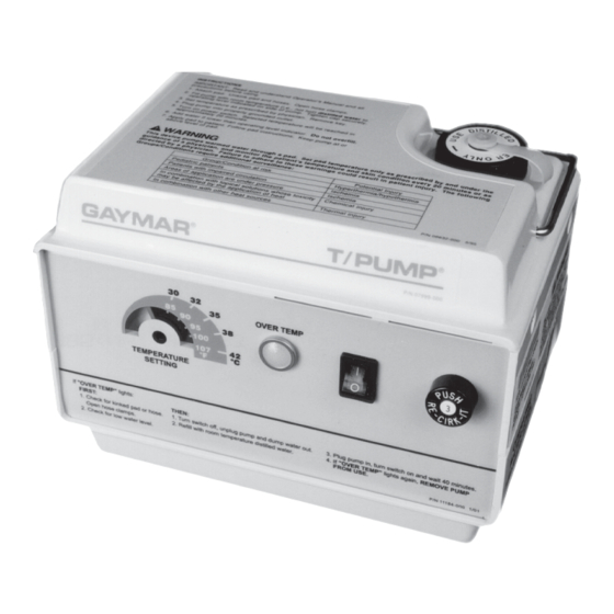
SERVICE MANUAL FEATURES TP500/TP500C T/PUMP Figure 2—T/Pump Features FEATURES Attached Hose 10 ft (305 cm) dual hose. Connectors allow pads to be connected to the pump (see figs. 3 and 4, p. 5). Tip-over Turns heater off if pump is tipped. Switch NOTE: This does not activate the OVER TEMP light. -
Page 6: Specifications
SERVICE MANUAL SPECIFICATIONS TP500/TP500C T/PUMP SPECIFICATIONS Size (approx.) " x 5- " x 6- " (20.6 cm x 14.3 cm x 15.9 cm) Weight (empty) 5 lbs, 2 oz (2.3 kg) Reservoir capacity 51 oz (1500 ml) maximum Flow rate 9 gph (34 lph) minimum with pad attached Ambient operating 60°F to 90°F (15.6°C to 32.2°C) -
Page 7: Operating Instructions
SERVICE MANUAL OPERATING INSTRUCTIONS TP500/TP500C T/PUMP T/Pumps are supplied with one of two types of hose connectors: ® TP500 T/Pumps have Clik-Tite connectors; TP500C T/Pumps have Colder-style connectors. ® CLIK-TITE CONNECTORS (on TP500): To attach Clik-Tite connectors from hose to pad: Insert male fittings into female fittings with a twisting motion (figs. - Page 8 SERVICE MANUAL OPERATING INSTRUCTIONS TP500/TP500C T/PUMP START-UP PROCEDURE 1 . Before filling, always attach a T/Pad to the T/Pump connector hose (see figs. 3 and 4, p. 5). Unkink pad and hose. Open hose clamps. 2 . Open the fill cap on top of the pump. Fill the pump with room temperature (i.e., not hot) distilled water to the operating level indicated on the side of the pump.
-
Page 9: Storage/Cleaning
To clean the fluid system, drain the pump. Fill the reservoir to the operat- ing level indicated on the side of the pump. Add 1/4 ounce GAYMAR catalog MTA33 germicidal or equivalent. Set the temperature indicator to its lowest setting (fully counterclockwise). -
Page 10: Theory Of Operation
WATER TEMPERATURE There are four devices that control the operation of the heater in the GAYMAR T/Pump: C O N T R O L • The temperature controller is thermistor actuated (fig. 5, item 1, p. 9). This controller is adjustable over a temperature range of 85°F to 107°F (29.4°C to 41.7°C). -
Page 11: T/Pump Components
SERVICE MANUAL T/PUMP COMPONENTS TP500/TP500C T/PUMP FIGURE 5—T/PUMP COMPONENTS (wire harness removed for clarity) BOTTOM... -
Page 12: Functional Check And Safety Inspeciton
12" long, 3" immersion (e.g., Brooklyn Thermometer #73544 or equivalent, Brooklyn Thermometer Co., Farmingdale, NY 11735) T/Pad --------- Any GAYMAR “12” or “22” series T/Pad; or, TP612 or TP622 pad as applicable TPC1 --------- GAYMAR T/Pump Test Cover Ground Resistance Tester... -
Page 13: Motor
If the pump motor is by Jakel, no oiling is required. If the pump motor is by Uppco, proceed with the following oiling instructions. 2 . Oil the pump motor every 6 months with Anderol #465 (GAYMAR P/N 77137-000) or equivalent to extend the life of the T/Pump motor. - Page 14 SERVICE MANUAL FUNCTIONAL CHECK TP500/TP500C T/PUMP TPC1 TEST COVER 1 . When connecting the test cover, do not remove any wiring connec- tions in the T/Pump. Simply clip the test cover alligator clips onto INSTALLATION terminals with the same color wire. 2 .
- Page 15 SERVICE MANUAL FUNCTIONAL CHECK TP500/TP500C T/PUMP FLOW RATE TEST 1 . Be sure the pad is flat and warm (approximately 107°F) and at the same level as the pump. Top of TPT9 float (see fig. 8, p. 23) should read at least 9 gph.
- Page 16 SERVICE MANUAL FUNCTIONAL CHECK TP500/TP500C T/PUMP 3 . To test the remaining thermostat, toggle the limit thermostat shorting switch to the position corresponding to the non-tripped thermostat. (This will short out the previously opened thermostat and allow the unit to continue heating.) Both thermostat indicator lights should be off and the HEATER INDICATOR light should be on.
-
Page 17: Inspection Form
SERVICE MANUAL INSPECTION FORM TP500/TP500C T/PUMP Inspection forms vary from hospital to hospital. The following sample form is intended as a guide so that the important parameters are recorded. l a i t i d n i l c i r c t i c r i t i u... -
Page 18: Disassembly/Reassembly
SERVICE MANUAL DISASSEMBLY/REASSEMBLY TP500/TP500C T/PUMP DANGER Risk of electric shock. Disconnect power before servicing the T/Pump. WARNING • Only qualified medical service personnel should repair the T/Pump. Improper repair may result in death or serious injury, equipment damage, or malfunction. •... - Page 19 SERVICE MANUAL DISASSEMBLY/REASSEMBLY TP500/TP500C T/PUMP 4 . It is necessary to remove the reservoir to remove the motor. Remove the eight (8) screws located around the inside wall of the tray. NOTE: It is not necessary to remove the front label (fig. 11, item 37, p.
- Page 20 SERVICE MANUAL DISASSEMBLY/REASSEMBLY TP500/TP500C T/PUMP 5 . On reassembly, put a small quantity of silicone heat sink compound (Dow Corning #340 or equivalent) around the thermistor capsule. Carefully insert the thermistor capsule into the hole on the brass manifold block. To avoid damaging the thermistor, do not push on the wires.
- Page 21 12" long, 3" immersion (e.g., Brooklyn Thermometer #73544 or equivalent) Insulated alignment tool T/Pad --------- Any GAYMAR “12” or “22” series T/Pad; or, TP612 or TP622 pad as applicable The calibration should be performed in a temperature controlled room, between 70°F and 75°F.
- Page 22 SERVICE MANUAL CALIBRATION TP500/TP500C T/PUMP 4 . Connect pump, pad, TPT9 flow/temp tester, and adaptor hose assem- bly if required (see fig. 8, p. 23). 5 . Fill pump with room temperature distilled water. 6 . Set Temp Dial to 107°F (maximum). NOTE: Be sure the temperature dial is always set to the maximum clockwise position when making calibration measurements and adjustments.
-
Page 23: Troubleshooting
SERVICE MANUAL T R O U B L E S H O O T I N G TP500/TP500C T/PUMP " " P g i l c t i , f f l l i f i t s e l l . -
Page 24: Tpc1 Test Covers
SERVICE MANUAL TPC1 TEST COVERS TP500/TP500C T/PUMP Figure 7A—‘NEW’ STYLE TPC1 TEST COVER CAUTION NOTE: Always match color of TPC1 wiring Route TPC1 wires as shown to avoid connections to color of T/Pump wiring. interference with T/Pump fan motor. -
Page 25: Functional Check Test Diagram
SERVICE MANUAL TEST SETUP TP500/TP500C T/PUMP Figure 8A—FUNCTIONAL CHECK TEST DIAGRAM (TP500) Figure 8B—FUNCTIONAL CHECK TEST DIAGRAM (TP500C) -
Page 26: Circuit Diagram For T/Pump
SERVICE MANUAL CIRCUIT DIAGRAM, T/PUMP TP500/TP500C T/PUMP Figure 9—CIRCUIT DIAGRAM... -
Page 27: Circuit Diagram For Tpc1 Test Cover
SERVICE MANUAL CIRCUIT DIAGRAMS, TEST COVERS TP500/TP500C T/PUMP Figure 10A—CIRCUIT DIAGRAM FOR TPC1 TEST COVER (To connect, refer to figure 7A) -
Page 28: Exploded View Of T/Pump
SERVICE MANUAL EXPLODED VIEW TP500/TP500C T/PUMP Figure 11—EXPLODED VIEW... -
Page 29: C A L I B R A T I O N
SERVICE MANUAL REPLACEMENT PARTS TP500/TP500C T/PUMP e t I i r c i t p ) t i n I [ h t i e t i i t c n I [ h t i e t i n i [ e t i , 3 , p i l... - Page 30 SERVICE MANUAL REPLACEMENT PARTS TP500/TP500C T/PUMP t p i , " l a i e t i l a t c i f e t i e t i e t i " 4 " 2 c r i t i u p i l o f i i t t...
- Page 31 SERVICE MANUAL REPLACEMENT PARTS TP500/TP500C T/PUMP t p i p i l t f a o f i ) d l , y l t s i , r e , " e t i e t i i t s...
-
Page 32: Warranties
PARTS and/or workmanship occur within 90 days from date of delivery provided the parts are returned with prior authorization* prepaid to GAYMAR I n d u s t r i e s . * For prior authorization on all items being returned to the factory and... - Page 33 SERVICE MANUAL TP500/TP500C T/PUMP...
- Page 34 SERVICE MANUAL TP500/TP500C T/PUMP...
- Page 35 SERVICE MANUAL TP500/TP500C T/PUMP...
- Page 36 ® GAYMAR INDUSTRIES, INC. 10 Centre Drive Orchard Park, NY 14127-2295 Phone: 1 800 828-7341 (716) 662-2551 FAX: ® ® T/PUMPS AND T/PADS 1 800 993-7890 ARE MADE IN THE USA (716) 662-0748...
Need help?
Do you have a question about the T/PUMP TP500 and is the answer not in the manual?
Questions and answers