
Related Manuals for Atari ASTEROIDS


Summary of Contents for Atari ASTEROIDS
- Page 1 TM-143 3rd printing « Λ . . SI ^ Λ / > Y e r f . Operation, Maintenance and Service Manual Complete with Illustrated Parts Lists...
- Page 2 GAME SERIAL NUMBER LOCATION Your game’s serial number is located on the outside rear of the game. The same number is also stamped on the chassis of the TV monitor, Game PCB and Regulator/Audio PCB. Please mention this number whenever calling your distributor for service.
- Page 3 1265 Borregas Avenue P. O. Box 427 Sunnyvale, California 94086 Copyright © 1979 by Atari, Inc. All rights reserved No part of this publication may be reproduced by any mechanical, photographic, or electronic process, or in the form of a phonographic re...
-
Page 4: Table Of Contents
Asteroids Table of Contents Location Setup New Parts....................Game Inspection..................Game Installation..................Voltage S e le ctio n ................. 3 Interlock and Power On/Off S w itc h e s ..........3 Game F u s e s ..................5 Self-Test Procedure..................5... - Page 5 Figure 14 Final Assembly..................20 Figure 15 Control Panel A s s e m b ly ................22 Figure 16 Asteroids Game PCB A sse m b ly............24 Figure 17 Regulator/Audio PCB A ssem bly............28 Figure 18 Power Supply Assembly for X-Y G am es..........30 Figure 19 Main Harness and Component A ssem bly..........
- Page 6 ---------------------------------------- N O TE---------------------------------- If reading through this manual does not lead to solving a certain maintenance problem, call Tele-Help™ at the Atari Customer Service office in your geographical area, as shown in one of the two maps below. Order all parts from the California office.
-
Page 7: New Parts
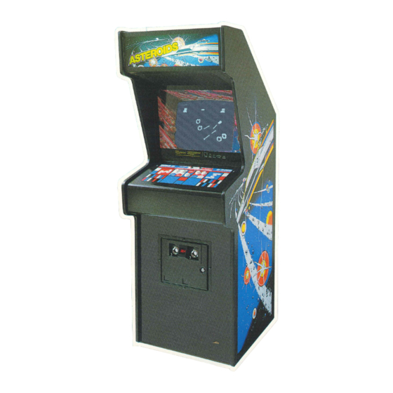
A. New Parts The Asteroids game has three new parts. If you have worked on Atari games in the past, then you should be aware of these important differences. The new parts are: • Power Supply Assembly. It covers a wider... - Page 8 Asteroids Figure 1 Overview of Game...
-
Page 9: Game Inspection
Asteroids B. Game Inspection C. Game Installation This new game is ready to play upon removal from the shipping carton. However, your careful inspec tion is needed to supply the final touch of quality Figure 2 Installation Requirements control. Please follow these steps to help us insure that your new game was delivered to you in good condition. -
Page 10: Figure 3 Power Supply
Figure 3 Power Supply Figure 4 Interlock and Power On/Off Switches... -
Page 11: Game Fuses
Asteroids Set the power on/off switch to the on position. Information on the TV monitor fuses is contained Within 30 seconds the TV monitor should in the TV monitor manual that is supplied with this game. display a picture. Slowly open the rear access panel. The TV monitor picture should disappear when the panel is opened approximately 2.5cm (1 inch). - Page 12 Asteroids Figure 6 Self-Test Procedure RESULTS IF TE S T RESULTS IF TE S T FAILS IN STR UCTIO N PASSES RAM FAILURE is indicated by a sequence of from 1 to 6 tones. A low-frequency T V monitor displays Set self-test tone is heard for each good RAM chip.
-
Page 13: Figure 7 Option Switch Settings
Asteroids Figure 7 Option Switch Settings T o change toggle positions of the sw itch assem bly, you When changing the options, verify proper results on the need not remove the game PCB. The sw itch, usually col TV m onitor display during self-test. A sw itch toggle in the... -
Page 14: Game Play
PLAYER 1 message disappears. Attract Mode The game ship for player 1 appears at the center of the display as four large asteroids appear and drift in The attract mode begins when power is applied to from the outer edges of the display. -
Page 15: High Score Initial Mode
A s te ro id s time. By pressing the LEFT ROTATE pushbutton, The game awards an extra ship each time a the displayed character steps through the alphabet player’s score reaches multiples of 10,000; i.e., one ship is awarded at 10,000 points, another ship at from A to Z. -
Page 16: Maintenance And Repair
Asteroids The Atari Asteroids game requires certain maintenance to keep it in good working order. Clean, properly maintained games attract players and earn more profits. The most important maintenance item is running the self-test every time you collect money from the cash box. -
Page 17: Cleaning
Asteroids Leaf Switch Replacement A. Cleaning All five of these leaf switches operate on 5 volts at The exterior of the game cabinet and the metal a very low current. Therefore, pitting of these and acrylic surfaces may be cleaned with any non... - Page 18 Asteroids LIGHT-EMITTING DIODE (L.E.D.) CONTACTS NORMALLY OPEN (N.O.) CONTACT NORMALLY CLOSED (N.C.) CONTACT L.E.D SWITCH: TO REMOVE TURN COUNTERCLOCKWISE To remove LED switch: Remove all wires from the faulty switch. Turn the switch counterclockwise while holding the black cone-shaped nut on the outside of the control panel.
-
Page 19: Tv Monitor Replacement
Asteroids D. TV Monitor Open the control panel as described in Section Replacement C, Opening the Control Panel. Be sure the game is unplugged from its wall outlet! Remove the acrylic TV monitor shield by sliding --- A its lower edge out. -
Page 20: Printed Circuit Board Replacement
PCB. the edge connector to the game PCB. Then Normally the only adjustments on the Asteroids unplug the edge connector on the game PCB. If game are option switch changes (made on the you are removing the Regulator/Audio PCB, 4-toggle and 8-toggle DIP switches). -
Page 21: Fluorescent Tube Replacement
Figure 12 illustrates the distribution of power in this game. Figure 13 illustrates the distribution of the Asteroids game. Sheet 1, Side A, includes infor mation that shows the arrangement of these dia signals. - Page 22 Asteroids Figure 12 Power Distribution...
- Page 23 Asteroids Figure 13 Signal Distribution...
-
Page 24: Illustrated Parts Lists
The purpose of this chapter is to provide you with the necessary information for ordering replacement parts for your Atari Asteroids game. Please note that, for simplicity, common hardware has been deleted from most of these parts lists. This includes screws, nuts, washers, bolts, etc. -
Page 25: Figure 14 Final Assembly
Asteroids 2 .6) d-PLCb 7 Places, Green Ground Wire N O T I C E T O A L L P E R S O N S R E C E I V I N G T H I S D R A W I N G... - Page 26 A cce ss Panel Assem bly A034986-01 A steroids Game PCB A ssem bly (PROM version)- -see Figure 16 A034986-02 Asteroids Game P CB A ssem bly (ROM version)— see Figure 16 A034485-01 Regulator/Audio P CB A ssem bly— see Figure 17 A034561-01 Power Supply Assem bly for X -Y Gam es—...
-
Page 27: Figure 15 Control Panel A S S E M B Ly
Asteroids Figure 14 Final Assembly, continued Parts List Item Part No. Description Lamp Socket C lip (each clip includes 2 pieces) 99-11006 18" 15-Watt Cool W hite Fluorescent Lamp 70-303 Manual for Quadrascan X -Y M onitor TM-146 A steroids Schem atic Drawings (Sheet 1) - Page 28 N O T I C E T O A L L P E R S O N S R E C E I V I N G T H I S D R A W I N G C O N F I D E N T I A L : R e p r o d u c t i o n f o r b i d d e n w i t h o u t...
-
Page 29: Figure 16 Asteroids Game Pcb A Sse M B Ly
Asteroids Figure 16 Asteroids Game PCB Assembly Parts List Part No. Description (Reference Designations and Locations in Bold) 27 Ohm, ± 5 % , 1 A W Resistor (R72) 100000-270 68 Ohm, ± 5 % , 1 A W Resistor... - Page 30 Asteroids Figure 16 Asteroids Game PCB Assembly, continued Parts List D escription (Reference D esignations and Locations in Bold) Part No. Item 31-1N756A 8.2V, ± 5 % , 1N756A Zener Diode (C R 1 3 ,14) 33-2 N3906 Typ e 2N3906 PNP Sw itching and Am plifying Transistor...
- Page 31 Asteroids Figure 16 Asteroids Game PCB Assembly, continued Parts List Part No. Description (Reference Designations and Locations in Bold) 37-7805 + 5V Voltage Regulator 37-7812 + 12V Voltage Regulator 37-7815 + 15V Voltage Regulator 37-7915 - 15V Voltage Regulator 38-MV5053...
- Page 33 N O T I C E T O A L L P E R S O N S R E C E I V I N G T H I S D R A W I N G C O N F I D E N T I A L R e p r o d u c t i o n f o r b i d d e n w i t h o u t...
-
Page 34: Figure 17 Regulator/Audio Pcb A Ssem Bly
Asteroids Figure 17 Regulator/Audio PCB Assembly Parts List Part No. Qty. D escription (Ref. Designations in Bold) 110000-010 1 Ohm, ± 5 % , 1 A W Resistor (R 1 0 ,19) 10 Ohm, ± 5 % , W Resistor... - Page 35 Asteroids TOP VIEW N O T I C E T O A L L P E R S O N S R E C E I V I N G T H I S D R A W I N G...
-
Page 36: Figure 18 Power Supply Assembly For X-Y Games
Asteroids Figure 18 Power Supply Assembly for X-Y Games Parts List D escription Part No. Qty. Item A034955-01 Power Supply Sub-Assem bly, Rev. A, consisting of the following 17 items: Base for Power Supply Chassis 034482-01 79-4411006 Panel-M ounting Non-Indicating 3AG Cartridge-Type Fuse Post... -
Page 37: Figure 19 Main Harness And Component A Ssem Bly
Asteroids N O T I C E T O A L L P E R S O N S R E C E I V I N G T H I S D R A W I N G C O N F I D E N T I A L... -
Page 38: Figure 20 Fluorescent Light A Ssem Bly
Asteroids N O T I C E T O A L L P E R S O N S R E C E I V I N G T H I S D R A W I N G C O N F I D E N T I A L :... -
Page 39: Figure 21 Coin Door A S S E M B Ly
Asteroids 21) 2 PLCS 15} 2 PLCS 9 ) 2 PLCS N O T I C E T O A L L P E R S O N S R E C E I V I N G T H I S D R A W I N G C O N F I D E N T I A L ;... - Page 40 Asteroids Figure 21 Coin Door Assembly Parts List Description Part No. Qty. » Front Bezel A s s y .— Used o n ly on -16 C o in D oor A ssy. (25<t) A007637-16 A007637-17 Front Bezel A s s y .— Used o n ly on -17 C o in D oor A s s y . (5 Fr) A007637-18 Front Bezel A s s y .—...
-
Page 41: Figure 22 Front Bezel A Sse M B Ly
Asteroids N O T I C E T O A L L P E R S O N S R E C E I V I N G T H I S D R A W I N G 6 PLCS... - Page 42 Asteroids N O T I C E T O A L L P E R S O N S R E C E I V I N G T H I S D R A W I N G C O N F I D E N T I A L :...
-
Page 43: Figure 23 New Coin D Oor
Asteroids REJECT BUTTON COVER SEE PARTS LIST (99-10055 thru 99-10059) PRICE PLATE SEE PARTS LIST COIN RETURN BUTTON ASSY . (99-10070, 99-10083 SEE PARTS LIST thru 99-10092) (99-10012 thru 99-10022) 72-JA1405B 99-10062 COIN DOOR ONLY SEE PARTS LIST 99-10054 (99-10009 thru 99-10010) - Page 44 Asteroids Figure 23 New Coin Door, continued Parts List D escription Part No. 100V Silicon Rectifier 1N4002 Diode 31-1N4002 65-441C General-usage low -force miniature sw itch 70-11-47 Miniature bayonet-base incandescent lamp, type #47 U.S. $1.00 coin mechanism 71-1201ADU 71-1201FC H...
- Page 45 Asteroids Figure 23 New Coin Door, continued Parts List D escription Part No. Coin inlet chute assem bly 99-10040 Coin counter assem bly 99-10041 99-10042 Coin sw itch assem bly for U.S. 25<t and Belgian 5 F r coins (silver wire)
- Page 46 Asteroids Figure 23 New Coin Door, continued Parts List Part No. Description Japanese Y100 price plate 99-10089 U.K. 10 P price plate 99-10090 Australian 20$ price plate 99-10091 Italian 100 Lire price plate 99-10092 Fish paper insulation 99-10094 Toggle sw itch 99-10095 “...
- Page 47 T h e use of any non-Atari parts m ay void yo u r warranty, according to the terms of the warranty. T h e use of any non-A tari parts may also adversely affect the safety of yo u r game and cause in...
- Page 48 ^ ATARI INC ' 1265 B O R R E G A S A V E N U E | V ^ P .O . B O X 427 ■ ^ e S U N N Y V A L E , C A L IF O R N IA 94086 Λ...
Need help?
Do you have a question about the ASTEROIDS and is the answer not in the manual?
Questions and answers