Advertisement
Quick Links
Use
CC1N7454en
20.11.2017
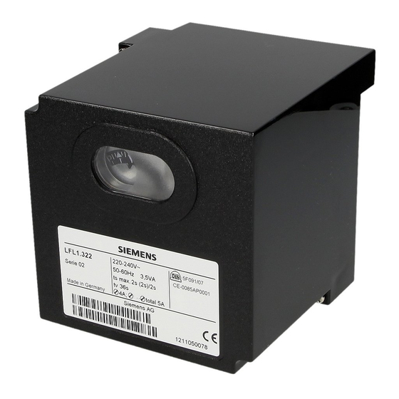
Gas Burner Control
Gas burner control
for atmospheric gas burners in intermittent operation
flame supervision with ionization probe
The LFL1.148 and this Data Sheet are intended for use by OEMs which integrate
the burner controls in their products!
For the supervision of 1- or 2-stage atmospheric gas burners
For use with medium- to high-capacity burners
For intermittent operation (at least 1 controlled shutdown in 24 hours)
The gas burner has a connection facility for an auxiliary fan or flue gas fan (e.g. for
condensing boilers)
Flame supervision is ensured by means of an ionization probe, 1 electrode is used for the
first stage and 1 for the second stage. Changeover takes place automatically after
release of the second fuel valve.
LFL1.148
Building Technologies Division
7
454
Advertisement

Related Manuals for Siemens LFL1.148


Summary of Contents for Siemens LFL1.148
- Page 1 flame supervision with ionization probe The LFL1.148 and this Data Sheet are intended for use by OEMs which integrate the burner controls in their products! For the supervision of 1- or 2-stage atmospheric gas burners ...
- Page 2 For safety reasons – self-test of the flame supervision circuit, etc. – at least one controlled shutdown must take place every 24 hours Before performing any wiring changes in the connection area of the LFL1.148, completely isolate the unit from the mains supply (all-polar disconnection) ...
- Page 3 Household and similar electrical appliances - Safety - Part 2-102: Particular requirements for gas, oil and solid-fuel burning appliances having electrical connections. The electrical connections of the LFL1.148 and the AGM comply with the requirements of EN 60335-2-102. EAC Conformity mark (Eurasian Conformity mark)
- Page 4 Local and currently valid legislation must be observed. Mechanical design The mechanical design of the LFL1.148 corresponds to that of the standard units of the LFL range (refer to Data Sheet N7451). 4/11 Building Technologies Division CC1N7454en 20.11.2017...
- Page 5 Type summary The type reference given below apply to the LFL1.148 without plug-in base and without flame detector. For ordering information for plug-in bases and other accessories, see Accessories. Gas burner control, without plug-in base LFL1.148 Article no.: BPZ:LFL1.148 Plug-in base not included in the delivery, must be ordered as a separate item!
- Page 6 Technical data For technical data – with the exception of the data listed below and the switching times of the switching mechanism – refer to Data Sheet N7451. General unit data Perm. length of detector cable Normal cable, laid separately Max.
- Page 7 Function In terms of control program and flame supervision (including test of the flame supervision circuit), the functions of the LFL1.148 correspond of those of the standard units of the LFL range. There is a difference however in the control of actuator (SA) and of load controller (LR), especially with regard to the air damper position on startup and closing of the air damper during controlled shutdown.
- Page 8 For example: Flame not extinguished After the reset, the burner control’s switching mechanism first returns to the start position and then initiates a burner restart. Connection diagram LFL1.148 19 11 15 22 3 21 12 5 14 6...
- Page 9 Basic diagram ION2 ION1 13 14 XIII VIII 9 10 18 7454a01/0204 Warning! Do not press reset bottom (EK) for more than 10 seconds! Control program 7454d02/0204 9/11 Building Technologies Division CC1N7454en 20.11.2017...
- Page 10 Diagram of switching mechanism 9 10 VIII 23 24 XIII 7454d01/0204 Legend Remote lockout indication Alarm Output signals of burner control Unit fuse Required input signals Main relay with contacts «ar...» Working relay Lockout relay with contacts «br...» Start command given by the control thermostat Fuel valve Startup sequence...
- Page 11 Dimensions Dimensions in mm LFL1.148 Plug-in base AGM410490550 / AGM14.1 7454m04/0305 27,5 27,5 2017 Siemens AG Building Technologies Division, Berliner Ring 23, D-76437 Rastatt Subject to change! 11/11 Building Technologies Division CC1N7454en 20.11.2017...