Advertisement
Quick Links
ESTIA 0-10 V interface
CAUTION
• For the details, refer to the installation manual of Hydro Unit.
• Read the "Precautions for safety" in the Hydro Unit installation manual before installation.
• To avoid personal injury (with sharp edges), be careful when handling the 0-10 V interface.
• Electrical work must be performed by a qualified electrician in accordance with the
installation manual.
• Be sure to turn off all main power supply switches or the circuit breaker before starting any
electrical work.
Accessory parts:
Installation
■
To connect the 0-10 V interface
TB04 for the 0-10 V interface wiring on the Hydro Unit E-BOX
• Communication wiring use 2-core non-polarity wires.
• Use 2-core shield wires to prevent noise trouble.
• In this case, for the system grounding, close (connect) the end of shield wires, and isolate the end of terminal.
• Be sure not input more than DC10 V to the analogue input terminals.
• The remote controller line (AB line) is available to connect maximum 2 units.
For example the header plus second remote controller or the KNX or the MODBUS or the Wireless Adapter or
the 0-10 V controller.
Wiring diagram
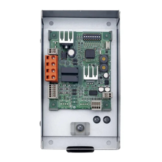
0-10 V interface
PCB
• The CN1 and CN5 connector can be removed from the
P.C. board.
• Please wire directly to the removed connector.
• Please wire as shown and return to the P.C. board.
CN5
INSTALLATION MANUAL
[ Model: HWS-IFAIP01U-E ]
Installation Manual (This manual) ×1
Hydro Unit
A B
CN1
A B
AI 1 0-10 V (+)
1
AI 2 0-10 V (+)
2
AI 3 0-10 V (+)
3
Common (-)
CN5
4
CN1
Terminal block (TB04) for the remote control wiring
Locally procured
2-core, non-polarity
Size: Total Length
0.5 ~ 2.5 mm²: Up to 50 m
■
Installation dimension
• Attach the rear case of the 0-10 V Interface to the wall.
Please procure screws locally.
93 mm
70 mm
4-Ø5 slotted hole
Locally procured
Size: Total Length
0.5 ~ 1.0 mm²: Up to 200 m
DDC
(procured locally)
English
Advertisement

Related Manuals for Toshiba HWS-IFAIP01U-E 0-10V


Summary of Contents for Toshiba HWS-IFAIP01U-E 0-10V
- Page 1 English INSTALLATION MANUAL ESTIA 0-10 V interface [ Model: HWS-IFAIP01U-E ] CAUTION • For the details, refer to the installation manual of Hydro Unit. • Read the “Precautions for safety” in the Hydro Unit installation manual before installation. • To avoid personal injury (with sharp edges), be careful when handling the 0-10 V interface. •...
- Page 2 This option allows Hydro Unit to be controlled either Setting temperatures or Capacity. Control of Setting temperature • DN 680 is set to “1”. • Set the input method for each setting temperature. Item Selectable value (Input from) Hot water setting temperature. 0: Not use AI 1: AI 1 2: AI 2...