Advertisement
Quick Links
Advertisement

Related Manuals for Fortis SK-600


Summary of Contents for Fortis SK-600
- Page 1 MAGNETIC FLYWHEEL SPIN BIKE (SK-600) FSMFWSPNBKA...
-
Page 2: Safety And Warnings
SAFETY & WARNINGS • Read all instructions before using the appliance and retain for reference. • This appliance is designed for consumer use: follow directions and use only as described. • Once fully assembled, inspect to ensure all hardware parts such as bolts, nuts and washers are positioned correctly and tightened securely. - Page 3 IN THE BOX Main Frame Handlebars Seat Handlebar Front Rear post stabiliser stabiliser Pedals...
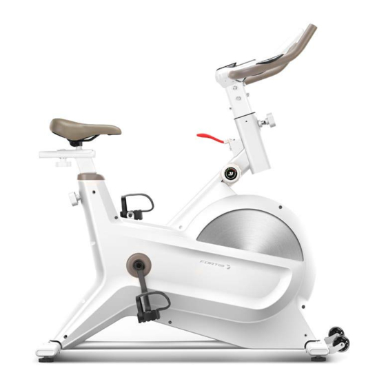
- Page 4 OVERVIEW...
- Page 5 Part name (dimensions in mm) Part name (dimensions in mm) Front stabiliser Bearing 6001-2RS (x4) idle pulley Ф39 x Ф34 x 24 Hexagon nut M8 x H5.5 x S14 (x4) Foot pad ф43 x 14 x M8 x 25. (x4) Wave washer d12 x Φ15.5 x 0.3 End cap PT70 x 30 x 20 (x4) Seat...
- Page 6 Part name (dimensions in mm) Part name (dimensions in mm) Belt Nut M12 x 1 x H5 x S19 (x3) Tension knob Handlebar End cap Φ25x16 (x2) Spring washer d6 (x2) Washer d6 x φ12 x 1.2 (x2) Foam Grip Φ23 x 3 x 420 (x2) Ring-shield d12 (x2) Main frame Washer d5 x Φ13 x 1...
- Page 7 ASSEMBLY Step 1 Attach the Front Stabiliser (1) to the Main Frame (81) using Screw (9), Spring Washer (10) and Washer (11). Attach the Rear Stabiliser (12) to the Main Frame (81) using the Screw (9), Spring Washer (10) and Washer (11). Screw the Pedal (No.
- Page 8 Step 2 Pass the Trunk line (88) through the Handlebar post (74). Then attach the Handlebar post (74) to the Handlebar (78) and tighten with the Screw (76), Spring Washer (10) and Washer (11). Rotate counter-clockwise and pull the Knob (13) out. Insert the Handlebar Post (74) and Trunk Line (88) into the Main Frame (81).
- Page 9 Step 3 Rotate counter-clockwise and pull the Knob (13) out. Adjust the Seat Post (31) to the desired position and secure with the Knob (13). Attach the Seat Slider (30) to the Seat Post (31), tighten and secure with the Washer (33) and the Knob (34).
- Page 10 Step 4 Remove the Battery Cover (95) from the Display (87) and then place x2 Batteries (96) into the Display (87). Ensure to align the “+” and “-” battery indicators correctly. Replace the Battery Cover (95) on the Display (87).
-
Page 11: Operation
OPERATION Functions Mode/Reset • Press the Display button to cycle through operations (see below). • Press and hold the Display button for 3 seconds to reset time, distance and calories. Operations SCAN: Display will rotate through the following functions: Time, Speed, Distance, Calories and Pulse. - Page 12 ADJUSTMENTS Balance • To adjust the balance of the bike, the Foot Pads (3) can be turned counter- clockwise.
- Page 13 Handlebars • The handlebars can be adjusted according to your height. • Rotate counter-clockwise and pull the Handlebar Adjustment Knob out. • The handlebar post can now be adjusted up and down (figure a). • Rotate the Handlebar Adjustment Knob clockwise and align the handlebar post hole (figure b).
- Page 14 Seat The seating position can be adjusted both vertically and horizontally. • To adjust, rotate counter-clockwise and pull the Seat Adjustment Knob (1) (vertical) or Seat Slider Adjustment Knob (2) (horizontal) out. The seat can now be adjusted (figure a). •...
- Page 15 Resistance and Braking • The tension can be adjusted by rotating the Tension Adjustment Knob (figure a). • The emergency brake handle above can be depressed during exercise to stop then bike immediately. Figure b Figure a Pedal Straps • Press the buckle and pull the strap up to loosen (figure a) or down to tighten (figure b).
- Page 16 Transporting TRANSPORTING • Ensure that the Handlebar is properly secured. • Stand directly in front of the Handlebars. • Grasp each side of the handlebar, place one foot on the front stabiliser and tilt the bike towards you until the transport wheels touch the ground.
- Page 17 NOTES...
- Page 20 Need more information? We hope that this user guide has given you the assistance needed for a simple set-up. For the most up-to-date guide for your product, as well as any additional assistance you may require, head online to help.kogan.com...
Need help?
Do you have a question about the SK-600 and is the answer not in the manual?
Questions and answers