Table of Contents
Advertisement
Quick Links
Advertisement
Table of Contents

Related Manuals for Timeguard Sure Time STW360


Summary of Contents for Timeguard Sure Time STW360
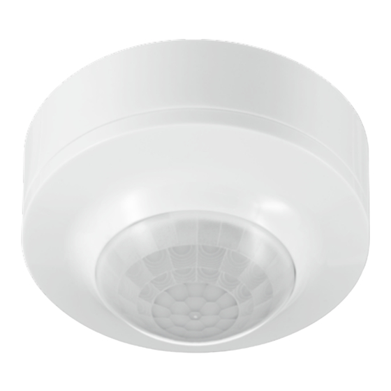
- Page 1 360° Surface Mount PIR Sensor Model: STW360...
-
Page 2: General Information
1. General Information These instructions should be read carefully and retained for further reference and maintenance. 2. Safety • Before installation or maintenance, ensure the mains supply to the PIR sensor is switched off and the circuit supply fuses are removed or the circuit breaker turned off. -
Page 3: Technical Specifications
3. Technical Specifications • 230V AC 50 Hz • This PIR sensor is of class II construction and must not be earthed • Motion Detection Range: Up to an 8 metre diameter at a 2.5m mounting height • Detection Angle: 360°... -
Page 4: Selecting A Location
4. Selecting a Location • The motion detector has number of detection zones, at various vertical and horizontal angles as shown (See image “A”). • The best all-round coverage is achieved with the unit mounted at the optimum height of 2.5 metres. •... -
Page 5: Installation
5. Installation • Ensure the mains supply is switched off and the circuit supply fuses are removed or the circuit breaker turned off. • An isolating switch should be installed to enable the power to be switched ON and OFF for maintenance purposes and to activate the manual/auto override function. - Page 6 • Insert mounting screws through the sensor assembly into the wall plugs and secure. Do not overtighten, if using a power screwdriver please ensure it is set to a low torque setting so as not to damage the unit.
-
Page 7: Connection Diagram
6. Connection Diagram • Connect the 230V 50Hz mains supply and load cables into the terminal block as follows; 230V 50Hz Mains Supply Load (Light Source) Live Supply (Brown or Red) to L Switch Live (Brown or Red) to L’ Neutral Supply (Blue or Black) to N Neutral Load (Blue or Black) to N... - Page 8 7. Walk Test Procedure (Test Mode) • The adjustment knobs located beneath the top cover of the sensor are factory set to “Walk Test Mode”. Double check they are set as follows; Time On setting – fully anti-clockwise Dusk (Lux) level setting – fully clockwise Time On Dusk (Lux) level Setting...
-
Page 9: Manual Override Mode
8. Setting Up for Automatic Operation (Auto Mode) • When the walk tests are complete, the unit can be adjusted for automatic operation. • The Time On setting controls how long the unit remains illuminated following activation and after all motion ceases. •... -
Page 10: Troubleshooting
10. Troubleshooting Problem Solution • The lamp stays ON Cover the PIR lens with a thick cloth. If the light at night. turns OFF, check the detection area for heat or a reflective source. If the light stays ON, check the wiring (See section 6. -
Page 11: Year Guarantee
Note: A proof of purchase is required in all cases. For all eligible replacements (where agreed by Timeguard) the customer is responsible for all shipping/postage charges outside of the UK. All shipping costs are to be paid in advance before a replacement... - Page 12 If you experience problems, do not immediately return the unit to the store. Telephone the Timeguard Customer Helpline; HELPLINE 020 8450 0515 or email helpline @ timeguard.com Qualified Customer Support Co-ordinators will be on-line to assist in resolving your query.
Need help?
Do you have a question about the Sure Time STW360 and is the answer not in the manual?
Questions and answers