
Related Manuals for Acer ASPIRE M3802(G)


Summary of Contents for Acer ASPIRE M3802(G)
- Page 1 Acer Aspire M3802(G) Service Guide Service guide files and updates are available on the ACER/CSD web; for more information, please refer to http://csd.acer.com.tw PRINTED IN TAIWAN...
-
Page 2: Revision History
Revision History Please refer to the table below for the updates made on this service guide. Date Chapter Updates... - Page 3 Copyright Copyright © 2009 by Acer Incorporated. All rights reserved. No part of this publication may be reproduced, transmitted, transcribed, stored in a retrieval system, or translated into any language or computer language, in any form or by any means, electronic, mechanical, magnetic, optical, chemical, manual or otherwise, without...
- Page 4 Any Acer Incorporated software described in this manual is sold or licensed "as is". Should the programs prove defective following their purchase, the buyer (and not Acer Incorporated, its distributor, or its dealer) assumes the entire cost of all necessary servicing, repair, and any incidental or consequential damages resulting from any defect in the software.
- Page 5 Conventions The following conventions are used in this manual: SCREEN MESSAGES NOTE WARNING CAUTION IMPORTANT Denotes actual messages that appear on screen. Gives additional information related to the current topic. Alerts you to any physical risk or system damage that might result from doing or not doing specific actions.
- Page 6 Service Guide. For ACER-AUTHORIZED SERVICE PROVIDERS, your Acer office may have a DIFFERENT part number code to those given in the FRU list of this printed Service Guide. You MUST use the list provided by your regional Acer office to order FRU parts for repair and service of customer machines.
-
Page 7: Table Of Contents
Table of Contents System Tour Features Block Diagram System Components Front Panel Rear Panel Hardware Specifications and Configurations Power Management Function(ACPI support function) System Utilities CMOS Setup Utility Entering CMOS setup Navigating Through the Setup Utility Setup Utility Menus System Disassembly Disassembly Requirements Pre-disassembly Procedure Removing the Side Panel... -
Page 8: System Tour
System Tour Features Below is a brief summary of the computer’s many feature: NOTE: The features listed in this section is for your reference only. The exact configuration of the system depends on the model purchased. Operating System Microsoft Windows Windows7 Home Premium 64bits •... -
Page 9: Hard Disk
Capacity support: • 1GB / 2GB DDRII 667/800 Un-buffered Non-ECC DIMM support • 1GB to 8GB Max memory support • Design Criteria: • Should meet Intel G43 Express Chipset platform design guide • Dual channel should be enabled always when plug-in 2 same memory size DDRII memory •... -
Page 10: Usb Ports
MS , MS-PRO , MS Duo , MS-PRO Due , Micro-MS(M2), xD type M and Type H card, CF type I and II, Microdrive) System BIOS Size: 2Mb Use SPI Flash • AMI Kernel with Acer skin • Power supply 500W/300W/250W in stable mode • Active PFC 220V for EMEA and China •... -
Page 11: Block Diagram
Block Diagram Chapter 1... -
Page 12: System Components
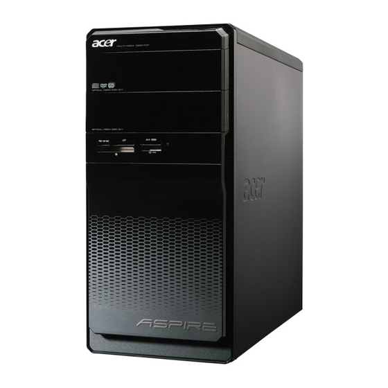
System Components This section is a virtual tour of the system’s interior and exterior components. Front Panel Chapter 1 Component Acer logo XD(XD-PICTURE) slot Micro SD/M2 slot CF I/II (CompactFlash Type I/II) slot Memory stick PRO slot SD(Secure Digital) solt... -
Page 13: Rear Panel
Rear Panel Component Power connector PS2 keyboard port VGA port HDMI port USB 2.0 ports Side Surround Surround Mic-in Expansion slot (graphics card and TV tuner card and Mode card) Line-in Line-out Center speaker/subwoofer jack USB 2.0 ports S/PDIF port LAN connector 1394 port System FAN... -
Page 14: Hardware Specifications And Configurations
LAN controller MAC controller: Intel ICH10R / PHY: Intel Boazman 82567V PCI-E Giga LAN HDD controller Intel ICH10R Chapter 1 Specification AMI Kernel with Acer skin P01-A0 SPI ROM SMBIOS 2.5 Support BBS spec 1st priority: HDD 2nd priority: CD-ROM... -
Page 15: Memory Combinations
Memory Combinations Slot Memory Slot 1 1MB,2GB Slot 2 1MB,2GB Slot 3 1MB,2GB Slot 4 1MB,2GB Maximum System Memory Supported System Memory Item Memory slot number Support Memory size per socket Support memory type Support memory interface Support memory voltage Support memory module package Support to parity check feature Support to error correction code (ECC) feature No... -
Page 16: Usb Port
SATA Interface Item SATA controller SATA controller resident bus Number of SATA channel Support bootable CD-ROM USB Port Item Universal HCI USB Class USB Connectors Quantity Environmental Requirements Item Specification Temperature Operating +5°C ~ +35°C Non-operating -20 ~ +60°C (Storage package) Humidity Operating 15% to 80% RH... -
Page 17: Power Management Function(Acpi Support Function)
Power Management Function(ACPI support function) Device Standby Mode Independent power management timer for hard disk drive devices(0-15 minutes,time step=1minute). • Hard Disk drive goes into Standby mode(for ATA standard interface). • Disable V-sync to control the VESA DPMS monitor. • Resume method:device activated (keyboard for DOS, keyboard &mouse for Windows. -
Page 18: System Utilities
System Utilities CMOS Setup Utility CMOS setup is a hardware configuration program built into the system ROM, called the complementary metal- oxide semiconductor (CMOS) Setup Utility. Since most systems are already properly configured and optimized, there is no need to run this utility. You will need to run this utility under the following conditions. When changing the system configuration settings •... -
Page 19: Entering Cmos Setup
Entering CMOS setup Turn on the server and the monitor. If the server is already turned on, close all open applications, then restart the server. During POST, press Delete. If you fail to press Delete before POST is completed, you will need to restart the server. The Setup Main menu will be displayed showing the Setup’s menu bar. -
Page 20: Setup Utility Menus
Setup Utility Menus The Setup Main menu includes the following main setup categories. Parameter Description Product Information This page shows the relevant information of the main board Standard CMOS Features This setup page includes all the items in standard compatible BIOS Advanced BIOS Features This setup page includes all the items of Award special enhanced features Advanced Chipset Features... -
Page 21: Product Information
Product Information The Product Information menu displays basic information about the system. These entries are for your reference only and are not user-configurable. Parameter Description Processor Type Type of CPU installed on the system. Processor Speed Speed of the CPU installed on the system. System Memory Total size of system memory installed on the system. -
Page 22: Standard Cmos Features
Standard CMOS Features Parameter Description System Date Set the date following the weekday-month-day-year format. System Time Set the system time following the hour-minute-second format. Halt On Determines whether the system will stop for an error during the POST. Chapter 2 Option All, But Keyboard No Errors... - Page 23 Advanced BIOS Feature Parameter Description Quick Boot Allows you to decrease the time it takes to boot the computer by shortening or skipping certain standard booting process. Quiet Boot When enabled, the BIOS splash screen displays during startup. When disabled, the diagnostic screen displays during startup. 1st/2nd/3rd/4th Boot Device Specifies the boot order from the available devices.
-
Page 24: Advanced Chipset Features
Advanced Chipset Features Parameter Description Intel EIST When enabled, this feature allows the OS to reduce power consumption. When disabled, the system operates at maximum CPU speed. Intel XD Bit When enabled, the processor disables code execution when a worm attempts to insert a code in the buffer preventing damage and worm propagation. -
Page 25: Integrated Peripherals
Integrated Peripherals Parameter Description Onboard SATA Controller Enables or disables the onboard SATA controller. Onboard SATA Mode Select an operating mode for the onboard SATA. Onboard USB Controller Enables or disables the onboard USB controller. Legacy USB Support Enables or disables support for legacy USB devices. USB Storage Emulation Enables or disables support for legacy USB devices. -
Page 26: Power Management Setup
Power Management Setup Parameter Description ACPI Suspend Mode Select an ACPI state. Deep power off mode Select the Deep power off Mode Power On by RTC Alarm Enables or Disables to wake up the system by RTC Alarm Function Power On by PCIE Devices Enables or disables to wake up the system from a power saving mode through an event on PCI Express device. -
Page 27: Pc Health Status
PC Health Status Parameter Description Smart FAN Enables or disables the smart system fan control function. Option Enabled Disabled Chapter 2... - Page 28 Frequency/Voltage Control Parameter Description Enable Clock to All DIMM/ Enables or disables control the clock to all DIMM/PCI Spread Spectrum Enables or disables the reduction of the mainboard’s EMI. Note: Remember to disable the Spread Spectrum feature if you are overclocking.
-
Page 29: Bios Security Features
BIOS Security Features Parameter Description Supervisor Password Indicates the status of the supervisor password. User Password Indicates the status of the user password. Change Supervisor Supervisor password prevents unauthorized access to the BIOS Setup Utility. Password Press Enter to change the Supervisor password. Setting a supervisor password Use the up/down arrow keys to select Change Supervisor Password menu then press Enter. -
Page 30: Load Default Settings
Load Default Settings The Load Default Settings menu allows you to load the default settings for all BIOS setup parameters. Setup defaults are quite demanding in terms of resources consumption. If you are using low-speed memory chips or other kinds of low-performance components and you choose to load these settings, the system might not function properly. -
Page 31: Exit Without Saving
Save & Exit Setup The Save & Exit Setup menu allows you to save changes made and close the Setup Utility. Exit Without Saving The Exit Without Saving menu allows you to discard changes made and close the Setup Utility. Chapter 2... -
Page 32: System Disassembly
System Disassembly This chapter contains step-by-step procedures on how to disassemble the desktop computer for maintenance and troubleshooting. Disassembly Requirements To disassemble the computer, you need the following tools: Wrist grounding strap and conductive mat for preventing electrostatic discharge • Flat-blade screwdriver •... -
Page 33: Pre-Disassembly Procedure
Pre-disassembly Procedure Before proceeding with the disassembly procedure, perform the steps listed below: Turn off the system and all the peripherals connected to it. Unplug the power cord from the power outlets. Unplug the power cord from the system. Unplug all peripheral cables from the system. Place the system unit on a flat, stable surface. -
Page 34: Removing The Side Panel
Removing the Side Panel Remove the two screws located on the rear edge of the side panel. Slide the side panel toward the back of the chassis until the tabs on the cover disengage with the slots on the chassis. Lift the side panel away from the server and put it aside for reinstallation later. -
Page 35: Removing The Heat Sink Fan Assembly
Removing the Heat Sink Fan Assembly WARNING:The heat sink becomes very hot when the system is on. NEVER touch the heat sink with any metal or with your hands. disconnect the fan cable from the mainboard. Use a long-nosed screwdriver to loosen the four screws on the heat sink, in the order as shown below. Lift the heat sink fan assembly away from the mainboard. -
Page 36: Removing The Processor
Removing the Processor IMPORTANT:Before removing a processor from the mainboard, make sure to create a backup file of all important data. WARNING:The processor becomes very hot when the system is on. Allow it to cool off first before handling. Release the load lever (1). Pull the load lever to the fully open, upright position (2) and lift the load plate (3). -
Page 37: Removing The Mode Card
Removing the Mode Card Release the Slot cover lock. Remove the screw from chassis. Gently pull the Modem card to remove it from the mainboard. Chapter 3... -
Page 38: Removing The Tv Card
Removing the TV Card Gently pull the TV card to remove it from the mainboard. Removing the VGA Card One finger Press the clip and the same time Gently pull the card to remove it from the mainboard. Chapter 3... -
Page 39: Removing The Hard Disk Drive
Removing the Hard Disk Drive Disconnect the data and power cables from the rear of the optical drive and the mainboard. Remove the HDD bracket Remove the screw that secures the HDD bracket to the ODD bracket. Lift the bracket up and turn it over. Chapter 3... - Page 40 Remove the HDD module Remove the eight screws secure the HDD module to the HDD bracket. Slide the HDD out of the bracket. Chapter 3...
-
Page 41: Removing The Front Bezel
Removing the Front Bezel Disconnect the LED cable. Release the Cable Clip. Disconnect the Power-led Cable. Release the front bezel from the chassis interior. Pull the bezel away from the chassis. Chapter 3... -
Page 42: Removing The Optical Drive
Removing the Optical Drive Disconnect the data and power cables from the rear of the optical drive. Remove Four screw from the optical drive. Pull the drive out of the drive. Chapter 3 Pow er cabl e D at a cabl e... -
Page 43: Removing The Cables
Removing the Cables Remove HDD Data and ODD Data cables from slot of M/B. Pow e- Led Cabl e HDD Cabl e Remove USB1/2/3 cable from M/B. Remove Card reader cable and Audio cable from M/B Fr ont USB Cabl e ( USB2) O DD Cabl e Rear I O USB Cabl e ( USB2) Rear SPDI F Cabl e... -
Page 44: Removing The System Fan
Removing the System FAN Remove System FAN cable from M/B. Release four screws according to the following picture. Take off the system fan from chassis. Chapter 3... -
Page 45: Removing The Power Supply
Removing the Power Supply Disconnect the 24-pin and 4-pin power supply cables from the mainboard. Remove the four screw that secures the power supply to the chassis. Lift the power supply module out of the chassis. Chapter 3... -
Page 46: Removing The Memory Modules
Removing the Memory Modules IMPORTANT:Before removing any DIMM from the memory board, make sure to create a backup file of all important data. Press the holding clips on both sides of the DIMM slot outward to release the DIMM. Gently pull the DIMM upward to pull it away from the M/B. Chapter 3... -
Page 47: Removing The Mainboard
Removing the Mainboard Remove the eight screws that secure the mainboard to the chassis. Lift the board from the chassis. Chapter 3... -
Page 48: System Troubleshooting
System Troubleshooting Please refer to generic troubleshooting guide for troubleshooting information relating to following topics: Power-On Self-Test (POST) • POST Check Points • POST Error Messages List • Error Symptoms List • Chapter 4 Chapter 4... -
Page 49: Power-On Self-Test (Post)
Power-On Self-Test (POST) Each time you turn on the system, the Power-on Self Test (POST) is initiated. Several items are tested during POST, but is for the most part transparent to the user. The Power-On Self Test (POST) is a BIOS procedure that boots the system, initializes and diagnoses the system components, and controls the operation of the power-on password option. -
Page 50: Bootblock Recovery Code Checkpoints
Checkpoint Restore CPUID value back into register. Give control to BIOS POST (ExecutePOSTKernel). See POST Code Checkpoints section of document for more information. System is waking from ACPI S3 state E1-E8 EC-EE OEM memory detection/configuration error. This range is reserved for chipset vendors & system manufacturers. - Page 51 POST Check Points Checkpoint Disable NMI, Parity, video for EGA, and DMA controllers. Initialize BIOS, POST, Runtime data area. Also initialize BIOS modules on POST entry and GPNV area. Initialized CMOS as mentioned in the Kernel Variable "wCMOSFlags." Check CMOS diagnostic byte to determine if battery power is OK and CMOS checksum is OK.
- Page 52 Checkpoint Initializes the silent boot module. Set the window for displaying text information. Displaying sign-on message, CPU information, setup key message, and any OEM specific information. Initializes different devices through DIM. See DIM Code Checkpoints section of document for more information. USB controllers are initialized at this point. Initializes DMAC-1 &...
-
Page 53: Dim Code Checkpoints
Checkpoint Uninstall POST INT1Ch vector and INT09h vector. Deinitializes the ADM module. Prepare BBS for Int 19 boot. End of POST initialization of chipset registers. Save system context for ACPI. Passes control to OS Loader (typically INT19h). 61-70 OEM POST Error. This range is reserved for chipset vendors & system manufacturers. The error associated with this value may be different from one platform to the next. -
Page 54: Post Error Messages List
POST Error Messages List If you cannot run the diagnostics program tests but did receive a POST error message, use "POST Error Messages List" to diagnose system problems. If you did not receive any error message, look for a description of your error symptoms in "Error Symptoms List"... -
Page 55: Storage Device
Message Displayed B: Drive Error The BIOS attempted to configure the B: drive during POST, but was unable to properly configure the device. This may be due to a bad cable or faulty diskette drive. Insert BOOT The BIOS attempted to boot from the A: drive, but could not find a proper boot diskette. diskette in A: Reboot and BIOS could not find a bootable device in the system and/or removable media drive does... - Page 56 Message Displayed 5th Slave Hard The IDE/ATAPI device configured as Slave in the 5th IDE controller could not be properly Disk Error initialized by the BIOS. This message is typically displayed when the BIOS is trying to detect and configure IDE/ATAPI devices in POST. 6th Master The IDE/ATAPI device configured as Master in the 6th IDE controller could not be properly Hard Disk...
-
Page 57: Virus Related
Message Displayed 6th Slave Drive The IDE/ATAPI device configured as Slave in the 6th IDE controller failed an ATAPI - ATAPI compatibility test. This message is typically displayed when the BIOS is trying to detect and Incompatible configure IDE/ATAPI devices in POST. S.M.A.R.T. - Page 58 Message Displayed Microcode BIOS could not find or load the CPU Microcode Update to the CPU. This message only Error applies to INTEL CPUs. The message is most likely to appear when a brand new CPU is installed in a motherboard with an outdated BIOS. In this case, the BIOS must be updated to include the Microcode Update for the new CPU.
- Page 59 Message Displayed CMOS CMOS settings are invalid. This error can be resolved by using AMIBIOS Setup. Settings Wrong CMOS CMOS contents failed the Checksum check. Indicates that the CMOS data has been Checksum changed by a program other than the BIOS or that the CMOS is not retaining its data due to malfunction.
-
Page 60: Usb Emodule Error Messages
USB eModule Error Messages Message Displayed Warning! Unsupported USB device found and disabled! Warning! Port 60h/64h emulation is not supported by this USB Host Controller! Warning! EHCI controller disabled. It requires 64bit data support in the BIOS. SMBIOS eModule Error Messages Message Displayed Not enough space in Runtime area!!. -
Page 61: Error Symptoms List
Error Symptoms List NOTE: To diagnose a problem, first find the error symptom in the left column. If directed to a check procedure, replace the FRU indicated in the check procedure. If no check procedure is indicated, the first Action/ FRU listed in right column is the most likely cause. - Page 62 Error Symptom Diskette drive does not work. Diskette drive read/write error. Diskette drive LED comes on for more than 2 minutes when reading data. Diskette drive LED fails to light, and the drive is unable to access for more than 2 minutes. Diskette drive test failed.
- Page 63 Error Symptom CD/DVD-ROM drive LED doesn't come on but works normally. CD/DVD-ROM drive LED flashes for more than 30 seconds before LED shutting off. Software asks to reinstall disc.Software displays a reading CD/DVD error. CD/DVD-ROM drive cannot load or eject when the system is turned on and its eject button is pressed and held.
- Page 64 Error Symptom Video memory test failed.Video adapter failed. Display problem: Incorrect colors No high intensity Missing, broken, or incorrect characters Blank monitor (dark) Blank monitor (bright) Distorted image Unreadable monitor Other monitor problems Display changing colors. Display problem not listed above (including blank or illegible monitor).
- Page 65 Error Symptom Executing software shutdown from Windows98 Start menu does not turn off the system. (Only pressing power switch can turn off the system). No system power, or power supply fan is not running. Any other problems. Action/FRU 1.Load default settings. 2.Reload software from Recovery CD.
-
Page 66: Undetermined Problems
Check all cables and connectors for proper installation. If the jumpers, switches and voltage settings are correct, remove or disconnect the following, one at a time: 10. Non-Acer devices External devices • Any adapter card (modem card, LAN card or video card, if installed) •... -
Page 67: Jumper And Connector Information
Chapter 5 Jumper and Connector Information M/B Placement Chapter 5... - Page 68 Label CPU Socket CONN,Socket,IntelPrescot tCPU,LGA- 775P,10u,G,SMD CPU_FAN CPU fan power header DIMM1~4 CONN,DIMM,DDRIII,1.5V, V/T,Blu,15u,G,DIP-240 GPIO1~2 General Purpose Input/ Output headers ATX_POWER M/B main power connector ME_DISABLE Front panel USB header SATA1~6 SATA data transfe connectors F_PANEL Front panel audio header F_USB1~4 Front panel USB headers CLR_CMOS...
-
Page 69: Jumper Setting
Jumper Setting The section explains how to set jumper for correct configuration of the mainboard. Setting Jumper Use the motherboard jumpers to set system configuration options. Jumpers with more numbered. When setting the jumpers, ensure that the jumper caps are Internal header pin definition Jumper/Header Name Chapter 5... - Page 70 Jumper/Header Name F_USB1 USB0- USB1- USB0+ USB1+ H5X2-P9E-Y F_USB2 USB0- USB1- USB0+ USB1+ H5X2-P9E-Y Function SYS FAN HEADER (3pin & 4 pin colay default:3 pin) FRONT PANEL HEADER FRONT USB HEADER FRONT USB HEADER Definition 1: GND 2: +12V 3: SENSE 4: PWM CONTROL(4 pin Fan) 1: SATALED+...
- Page 71 Jumper/Header Name F_USB3 USB0- USB1- USB0+ USB1+ H5X2-P9E-Y -O Chapter 5 Function FRONT USB HEADER FRONT USB HEADER FRONT AUDIO HEADER SPDIF HEADER SPDIF HEADER Definition 1: USBVCC_3 2: USBVCC_3 3: USB5_XN 4: USB7_XN 5: USB5_XP 6: USB7_XP 7:GND 8: GND 9: KEY 10: GND 1: USBVCC_4...
- Page 72 Jumper/Header Name Connector pin definition Connector Name Function FRONT 1394 HEADER 1: T_PA0+ 2: T_PA0- 3: GND 4: GND 5: T_PB0+ 6: T_PB0- 7: CPWR1 8: CPWR1 9: KEY 10: GND Function PSKBMS CONN 1: KBDATA 2: NC 3: GND 4: KBVCCSB 5: KBCLK 6: NC...
- Page 73 Connector Name Chapter 5 Function VGA CONN 1: RED 2: GREEN 3: BLUE 4,11: NC 9: HDMIVCC 12: VDAC_SDAT 13: HSYNC 14: VSYNC 15: VDAC_SCLK 5,6,7,8,10,16,17: GND USB+1394 CONN 1: USBVCC_5 2: USB9_XN 3: USB9_XP 4: AUGND2 5: USBVCC_5 6: USB8_XN 7: USB8_XP 8: AUGND2 9: CPWR2...
- Page 74 Connector Name Function USB+LAN CONN 1:USBVCC_6 12:MDI1_P 2:USB10_XN 13:MDI1_N 3:USB10_XP 4:AUGND2 5:USBVCC_6 16:MDI3_P 6:USB11_XN 17:MDI3_N 7:USB11_XP 8:AUGND2 9:LAN_1P8V 10: MDI0_P 11: MDI0_N 19:LAN_LED2 20:LAN_LED1 21: LAN_LED0 22: CL_3P3V G1,G2,G3,G4,G5,G6,G7, G8: AUGND2 SATA CONN 1: GND 2: SATA0_TX_P 3: SATA0_TX_N 4: GND 5: SATA0_RX_N 6: SATA0_RX_P 7: GND...
- Page 75 Connector Name Chapter 5 Function SATA CONN 1: GND 2: SATA2_TX_P 3: SATA2_TX_N 4: GND 5: SATA2_RX_N 6: SATA2_RX_P 7: GND SATA CONN 1: GND 2: SATA3_TX_P 3: SATA3_TX_N 4: GND 5: SATA3_RX_N 6: SATA3_RX_P 7: GND SATA CONN 1: GND 2: SATA4_TX_P 3: SATA4_TX_N 4: GND...
- Page 76 Connector Name Function ATX_POWER CONN 1:VCC3 2:VCC3 3: GND 4:VCC 5:GND 6:VCC 7:GND 8:ATX_PWRGD 20:NC 9:5VSB 10:+12V 11:+12V 12:VCC3 ATX12V CONN 1: GND 2: GND 3: +12V_4P 4: +12V_4P Definition 13:VCC3 14:-12V 15:GND 16:ATX_PSON_L 17:GND 18:GND 19:GND 21VCC 22:VCC 23:VCC 24:GND Chapter 5...
-
Page 77: Fru (Field Replaceable Unit) List
To scrap or to return the defective parts, follow the local government ordinance or regulations on • how to dispose it properly, or follow the rules set by your regional Acer office on how to return it. This document will be updated as more information about the FRU list becomes available. -
Page 78: Aspire M3802 Exploded Diagram
Aspire M3802 Exploded Diagram NOTE: This section will be updated when more information becomes available. Chapter 6... - Page 79 Description 6IN5-WITH-1394-X1-ASH-1 CDROM-NEC-4DX ACER-M330-MAIN-CHASSIS HOD-BKT M330-SIDE-DOOR CHASSIS-SUPPORT ATX-POWER-AA PCI-DOOR REAR-CHASSIS ODD-CAGE TOP-BEZEL TOP-RORATE-DOOR USB-ASM-NEW M330-TOP-COVER-METAL Chapter 6 Description MB-SUPPORT M330-SUB-CHASSIS POWER-PCBA M330-LIGHT LIGHT-COSTIC POWER-BOTTON ODD-BUTTON COSMETIC-LOOP-BOTTON ODD-COVER LENS-NEW CHAGE-COVER LED-3 M330-SPRING-ODD-BUTTON A3-ASPRIRE-ODD-DOOR-SPRING...
-
Page 80: Aspire M3802 Fru List
Aspire M3802 FRU List Category MAINBOARD MB Kit HimalayanII_D2 Intel G43 ICH10R GMA X4500 384M Intel 82567V Giga LAN ATX W/ 1394 V1.0 LF w/ EuP Lot6 CARD READER IOI 16-in-1 CR M1/M3 w/3.5", USB2.0, UsBSET UT330-LK w/micro SD, M2 KYE 16-in-1 CR M1/M3 w/3.5", USB2.0, Realtek RTS-5181 w/micro SD, M2 CPU COOLER FAN COOLER P4_SKT775 PKP367 W/I SUNON 4000RPM... - Page 81 Category Core 2 Quad Q8200 (2.33G 4M 1333FSB) 95W , M1 Core 2 Duo E8500 (3.16G 6M 1333FSB) , 65W , E0 Core 2 Duo E8400 (3.0G 6M 1333FSB) , 65W , E0 Core 2 Duo E7600 (2.66G 3M 1066FSB) , 65W , R0 Core 2 Duo E7500 (2.66G 3M 1066FSB) , 65W , R0 Core 2 Duo E7300 (2.66G 3M 1066FSB) , 65W , M0 Pentium Dual Core E6300 (2.8G 2M 1066FSB) , 65W , R-0...
- Page 82 Category 1.5TB 640GB 750GB DH-16D5S Win7 DH-20N(H/F) Win7 GH-41F(H/F) Win7 non-Labelflash DH-16AASH (H/F) Win7 non-Labelflash DH-4O3S Win7 CH-10F Win7 non-Labelflash DH-6E2S Win7 non-Labelflash VGA CARD GEFORCE GT220 1GB DDR2 (128BITS) SAMSUNG DVI HDMI VGA ATX BRACKET GEFORCE G210 512MB DDR2 (64BITS) SAMSUNG DVI HDMI VGA ATX BRACKET HD4650 1GB DDR 2 (128BITS) SAMSUNG DVI HDMI VGA W/ATX BKT ROHS...
- Page 83 Category MOUSE Acer 0810 Project PS2 Optical mouse Logitech 0810_USB Optical mouse USB M-UAY-ACR2 Lite-On PS2 optical mouse PS2 SM-9620 Lite-On USB optical USB SM-9625 Logitech USB Optical mouse USB M-UAE96 GS KEYBOARD Keyboard CHICONY KB-0759 PS/2 Standard 104KS Black US w/o eKey...
- Page 84 Category Keyboard CHICONY KB-0759 PS/2 Standard 105KS Black Norwegian w/o eKey Keyboard CHICONY KB-0759 PS/2 Standard 104KS Black Hebrew w/o eKey Keyboard CHICONY KB-0759 PS/2 Standard 105KS Black Polish w/o eKey Keyboard CHICONY KB-0759 PS/2 Standard 105KS Black Slovenian w/o eKey Keyboard CHICONY KB-0759 PS/2 Standard 105KS Black Slovak w/o eKey Keyboard CHICONY KB-0759 PS/2 Standard 104KS Black Russian w/o eKey...
- Page 85 Category Keyboard LITE-ON SK-9620 PS/2 Standard 107KS Black Brazilian Portuguese w/o eKey Keyboard LITE-ON SK-9620 PS/2 Standard 109KS Black Japanese w/o eKey Keyboard LITE-ON SK-9620 PS/2 Standard 105KS Black German w/o eKey Keyboard LITE-ON SK-9620 PS/2 Standard 105KS Black Italian w/o eKey Keyboard LITE-ON SK-9620 PS/2 Standard 105KS Black French w/o eKey Keyboard LITE-ON SK-9620 PS/2 Standard 105KS Black Swedish w/o eKey Keyboard LITE-ON SK-9620 PS/2 Standard 105KS Black UK w/o eKey...
- Page 86 Category Keyboard CHICONY KU-0760 USB Standard 104KS Black Traditional Chinese w/o eKey Keyboard CHICONY KU-0760 USB Standard 104KS Black Simplified Chinese w/o eKey Keyboard CHICONY KU-0760 USB Standard 104KS Black US International w/o eKey Keyboard CHICONY KU-0760 USB Standard 104KS Black Arabic/English w/ o eKey Keyboard CHICONY KU-0760 USB Standard 104KS Black Thailand w/o eKey...
- Page 87 Category Keyboard CHICONY KU-0760 USB Standard 105KS Black Danish w/o eKey Keyboard CHICONY KU-0760 USB Standard 104KS Black Czech w/o eKey Keyboard CHICONY KU-0760 USB Standard 105KS Black Romanian w/o eKey Keyboard CHICONY KU-0760 USB Standard 105KS Black Turkish w/o eKey Keyboard CHICONY KU-0760 USB Standard 105KS Black Spanish Latin w/o eKey Keyboard CHICONY KU-0760 USB Standard 105KS Black Turkish-Q w/o...
- Page 88 Category Keyboard LITE-ON SK-9625 USB Standard 105KS Black Icelandic w/o eKey Keyboard LITE-ON SK-9625 USB Standard 105KS Black Norwegian w/o eKey Keyboard LITE-ON SK-9625 USB Standard 104KS Black Hebrew w/o eKey Keyboard LITE-ON SK-9625 USB Standard 105KS Black Polish w/o eKey Keyboard LITE-ON SK-9625 USB Standard 105KS Black Slovenian w/o eKey Keyboard LITE-ON SK-9625 USB Standard 105KS Black Slovak w/o eKey Keyboard LITE-ON SK-9625 USB Standard 104KS Black Russian w/o eKey...
-
Page 89: Intel Raid Sop
Intel RAID SOP INTEL® MATRIX STORAGE TECHNOLOGY CHECK(DOS) 1.Intel(R) Matrix Storage Manager option ROM 1-1: Create SATA RAID 0 Step 1:Shut down the EUT, unplug the power cable,connect two SATA HDDS to EUT , check the EUT all devices are connect/plug ok. Step 2:Press "PWR-BTTN"... - Page 90 Step 6:Create RAID 0 Mode,enter the RAID name,such as "MyRaid0",default is"Volume0". Picture2 Step 7:Select "RAID0(Stripe)" at "RAID Level". Picture3 Chapter 7...
- Page 91 Step 8:You can select the "Strip Size" and define RAID capacity in "Capactity". Picture4 Step 9:Press "Create Volume" to create RAID0,it will pop the warning message that all data will be lost,"press "Y" to confirm it. Picture5 Step 10:It will back to create RAID interface,then press "ESC" or select 4 to exit and install OS. Chapter 7...
- Page 92 1-2: Create SATA RAID 1 Step 1:Shut down the EUT, unplug the power cable,connect two SATA HDDS to EUT , check the EUT all devices are connect/plug ok. Step 2:Press "PWR-BTTN" to power on the EUT,Load BIOS default setting . Step 4:During BIOS post, press <Ctrl-I>...
- Page 93 Step 7:Select "RAID5(Parity)" at "RAID Level". Step 8:You can select the "Strip Size" and define RAID capacity in "Capactity". Step 9:Press "Create Volume" to create RAID5,it will pop the warning message that all data will be lost,"press "Y" to confirm it. Step 10:It will back to create RAID interface,then press "ESC"...
- Page 94 Step 8:Select two HDDs in "Disk" by space key. Picture8 Step 9:Press "Enter" to finish HDD selection and it will back to RAID creation interface. Step 10:Repeat RAID1 creation step and exit,then install OS. Chapter 7...
-
Page 95: Intel Raid Sop (Windows For Win7)
Intel RAID SOP (Windows for WIN7) 2.Intel(R) Matrix Storage Console 2-1:Create a“RAID Ready” System into" RAID 0" with two Hard Drives by‘Create RAID Volume from Existing HDD Drive ’. Step 1:Install Win7 OS with one SATA HDD. Step 2:Shut down the system,then add one Serial ATA hard drive in the system. Step 3:Boot to OS desktop, open the Intel®... - Page 96 Step 5:Click "Next" at create a RAID volume window. Picture3 Step 6:Key the name in "Volume Name" and select "RAID 0" in RAID Level. Picture4 Step 7:Select minimum HDD as "Source Hard Drive". Picture5 Chapter 7...
- Page 97 Picture6 Step 8:Select Menber Hard Drive(s). Picture7 Chapter 7...
- Page 98 Step 9:Specify Volume Size then press "next". Step 10:Press "next" to finish setup and start create RAID0. Step 11:It may takes half and hours to create RAID0.After create completely,it will ask to reboot to finish create RAID0. 2-2:Create a“RAID Ready” System into" RAID 1" with two Hard Drives by‘Create RAID Volume from Existing HDD Drive ’.
- Page 99 Step 6:Key the name in "Volume Name" and select "RAID 1" in RAID Level. Step 7:Select minimum HDD as "Source Hard Drive". Step 8:Select Menber Hard Drive(s). Step 9:Specify Volume Size then press "next". Step 10:Press "next" to finish setup and start create RAID1. Step 11:It may takes half and hours to create RAID1.After create completely,it will ask to reboot to finish create RAID1.
- Page 100 Step 6:Key the name in "Volume Name" and select "RAID 5" in RAID Level. Picture11 Step 7:Select minimum HDD as "Source Hard Drive". Picture12 Chapter 7...
- Page 101 Step 8:At least select two HDD as Menber Hard Drive(s). Step 9:Specify Volume Size then press "next". Step 10:Press "next" to finish setup and start create RAID5. Step 11:It may takes half and hours to create RAID5.After create completely,it will ask to reboot to finish create RAID5.
- Page 102 Step 7:Select two HDDs as "Source Hard Drive". Step 8:At least select two HDD as Menber Hard Drive(s). Step 9:Specify Volume Size then press "next". Step 10:Press "next" to finish setup and start create RAID 10. Step 11:It may takes half and hours to create RAID 10.After create completely,it will ask to reboot to finish create RAID10.
- Page 103 Step 5:Click "Next" at create a RAID volume window. Step 6:Key the name in "Volume Name" and select "RAID 0" in RAID Level. Step 7:At least select two HDDs as "Volume Location". Picture17 Step 8:Specify Volume Size then press "next". Picture18 Step 9:Press "next"...
- Page 104 2-6:Create a“RAID Ready” System into" RAID 1" with two Hard Drives by ‘Create RAID Volume ’. Step 1:Install WIN7 OS with one SATA HDD. Step 2:Shut down the system,then add another two serial ATA hard drives in the system. Step 3:Boot to OS desktop, open the Intel® Matrix Storage Console. Step 4:Click on the by‘Create RAID Volume’...