Hach POCKET COLORIMETER II Instruction Manual
Analysis system
Hide thumbs
Also See for POCKET COLORIMETER II:
- User manual (188 pages) ,
- Basic user manual (142 pages) ,
- Instruction manuals (116 pages)

Related Manuals for Hach POCKET COLORIMETER II


Summary of Contents for Hach POCKET COLORIMETER II
- Page 1 59575-88 ™ POCKET COLORIMETER ANALYSIS SYSTEM INSTRUCTION MANUAL Fluoride (F) © Hach Company, 2006. All rights reserved. Printed in the U.S.A. te/dk 12/06 3ed...
- Page 2 Important Note This manual is intended for use with the following Pocket Colorimeter II instrument: Fluoride (F) Cat. No. 58700-05 1—2...
-
Page 3: Table Of Contents
Table of Contents Safety Precautions ....................1—7 Laboratory Safety ....................1—7 Use of Hazard Information................1—7 Precautionary Labels..................1—8 Specifications ......................1—9 Instrument Keys and Display ................1—13 Instrument Cap Cord ..................1—14 Fluoride, Pipet Method ..................1—17 Measuring Hints ....................1—17 Fluoride, AccuVac®... - Page 4 Table of Contents, continued Instrument Operation ..................2—3 Key Functions......................2—3 Menu Selections ....................2—4 Switching Ranges....................2—4 Setting the Time ....................2—4 Recalling Stored Measurements ................2—5 Battery Installation .....................2—6 Error Codes ......................2—9 Error Messages ....................2—9 Standard Calibration Adjust ................2—13 User-Entered Calibration .................2—15 Overview ......................2—15 Calibration Procedure Using Prepared Standards.........2—17 Entering a Predetermined Calibration Curve..........2—20 Editing a User-entered or Factory Calibration Curve........2—22...
- Page 5 Table of Contents, continued Certification ......................2—29 How to Order ......................2—35 Repair Service ...................... 2—37 Warranty ........................ 2—38 1—5...
- Page 6 1—6...
-
Page 7: Safety Precautions
Safety Precautions Please read this entire manual before unpacking, setting up, or operating this instrument. Pay particular attention to all danger and caution statements. Failure to do so could result in serious injury to the operator or damage to the equipment. To ensure the protection provided by this equipment is not impaired, do not use or install this equipment in any manner other than that which is specified in this manual. -
Page 8: Precautionary Labels
Safety Precautions, continued DANGER Indicates a potentially or imminently hazardous situation which, if not avoided, could result in death or serious injury. CAUTION Indicates a potentially hazardous situation that may result in minor or moderate injury. NOTE Information that requires special emphasis. Precautionary Labels Please pay particular attention to labels and tags attached to the instrument. -
Page 9: Specifications
Specifications Lamp: Light emitting diode (LED) Detector: Silicon photodiode Photometric precision: ± 0.0015 Abs Filter bandwidth: 15 nm Wavelength: 580 nm Absorbance range: 0–2.5 Abs Dimensions: 3.2 x 6.1 x 15.2 cm (1.25 x 2.4 x 6 inches) Weight: 0.2 kg (0.43 lbs) ®... - Page 10 1—10...
- Page 11 OPERATION DANGER Handling chemical samples, standards, and reagents can be dangerous. Review the necessary Material Safety Data Sheets and become familiar with all safety procedures before handling any chemicals. DANGER La manipulation des échantillons chimiques, étalons et réactifs peut être dangereuse. Lire les Fiches de Données de Sécurité...
- Page 12 1—12...
-
Page 13: Instrument Keys And Display
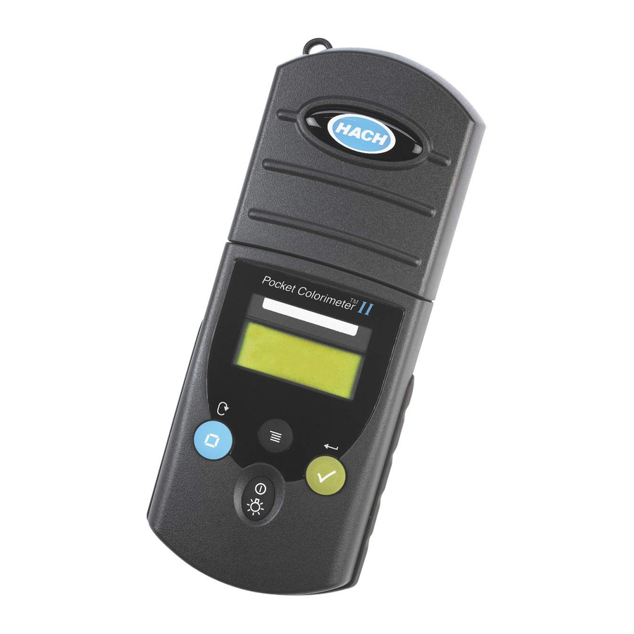
Instrument Keys and Display Item Description POWER/BACKLIGHT ZERO/SCROLL MENU Numeric Display Range Indicator Range Indicator Menu Indicator Calibration Adjusted Indicator Battery Low Indicator READ/ENTER 1—13... -
Page 14: Instrument Cap Cord
Instrument Cap Cord The instrument cap for the Pocket Colorimeter™ II doubles as a light shield. Accurate measurements cannot be obtained unless the sample or blank is covered with the cap. Use the instrument cap cord to secure the cap to the body of the colorimeter and prevent loss of the cap. - Page 15 Instrument Cap Cord, continued Figure 1 Attaching the Instrument Cap Cord 1—15...
- Page 16 1—16...
-
Page 17: Fluoride, Pipet Method
(D004) in sufficient concentration to be regulated as a hazardous waste for Federal RCRA. Note: The Pocket Colorimeter II is designed to measure solutions contained in sample cells. dip the meter in the sample or pour the sample directly into the cell holder. DO NOT * Adapted from Standard Methods for Examination of Water and Wastewater. - Page 18 Fluoride, Pipet Method, continued Press the key to Use a pipet and pipet Rinse the 10-mL pipet POWER turn the meter on. filler to transfer 10.0 mL of several times with small deionized water into a portions of the sample. The arrow should indicate clean, dry sample cell (the Transfer 10.0 mL of sample...
- Page 19 Fluoride, Pipet Method, continued HRS MIN SEC HRS MIN SEC Use a pipet filler and 2- Wait 1 minute. Place the blank in the mL Class A volumetric pipet cell holder. to transfer 2.0 mL of SPADNS Reagent into each sample cell.
- Page 20 Fluoride, Pipet Method, continued Cover the blank with the Press Place the prepared ZERO/SCROLL instrument cap. sample in the cell holder. The display will show “- - - -” then 0.00. Remove the blank from the cell holder. 1—20...
- Page 21 Fluoride, Pipet Method, continued If the instrument Cover the sample cell Press Note: READ/ENTER with the instrument cap. shows a flashing 2.20 (over The display will show range), dilute the sample “- - - -”, followed by results with an equal volume of –...
- Page 22 Fluoride, Pipet Method, continued Sampling and Storage Sampling and Storage on page 1—30. Accuracy Check Accuracy Check on page 1—30. Method Performance Method Performance on page 1—31. Standard Calibration Adjust Standard Calibration Adjust on page 2—13. Interferences Interferences on page 1—33.
- Page 23 Fluoride, Pipet Method, continued Required Reagents Description Units Cat. No. SPADNS Reagent Solution for Fluoride ........500 mL ..444-49 Water, deionized..................4 L ..272-56 Required Apparatus Pipet Filler, safety bulb ..............each ..14651-00 Pipet, volumetric, Class A, 2.0 mL............ each ..14515-36 Pipet, volumetric, Class A, 10.0 mL..........
- Page 24 Fluoride, Pipet Method, continued Optional Reagents, continued Description Units Cat. No. Silver Sulfate, ACS ................113 g ..334-14 Sodium Arsenite Solution ...........100 mL MDB ..1047-32 Spec√ ™ Secondary Standards Kit, Fluoride ........each ..27125-00 ® StillVer Distillation Solution ............500 mL ..446-49 Optional Apparatus Cylinder, graduated, 100 mL ..............each ..
-
Page 25: Fluoride, Accuvac® Method
(D004) in sufficient concentration to be regulated as a hazardous waste for Federal RCRA. Note: The Pocket Colorimeter II is designed to measure solutions contained in sample cells. dip the meter in the sample or pour the sample directly into the cell holder. DO NOT * Adapted from Standard Methods for Examination of Water and Wastewater. - Page 26 Fluoride, AccuVac® Method, continued Press the key to Collect at least 40 mL of Fill a SPADNS Fluoride POWER turn the meter on. sample in a 50-mL beaker. AccuVac Ampul with Fill another 50-mL beaker sample. Fill another SPADNS The arrow should indicate with at least 40 mL of Fluoride AccuVac Ampul channel 2.
- Page 27 Fluoride, AccuVac® Method, continued HRS MIN SEC HRS MIN SEC Quickly invert the ampuls Wait 1 minute. Place the blank in the several times to mix. cell holder. Wipe off any liquid or Note: fingerprints. 1—27...
- Page 28 Fluoride, AccuVac® Method, continued Cover the blank with the Press Place the prepared ZERO/SCROLL instrument cap. sample in the cell holder. The display will show “- - - -” then 0.0. Remove the blank from the cell holder. 1—28...
- Page 29 Fluoride, AccuVac® Method, continued If the instrument Cover the sample cell Press Note: READ/ENTER with the instrument cap. shows a flashing 2.2 (over The display will show range), dilute the sample “- - - -”, followed by results with an equal volume of –...
-
Page 30: Sampling And Storage
A variety of standard solutions covering the entire range of the test is available from Hach. Use these in place of the sample to verify technique. Note: Minor variations between lots of reagent become measurable above 1.5 mg/L. While results in this region are usable for most purposes, better accuracy may be obtained by diluting a fresh sample 1:1 with deionized water and re-testing. -
Page 31: Method Performance
Fluoride, AccuVac® Method, continued Method Performance Typical Precision (95% Confidence Interval): – 1.0 ± 0.1 mg/L F (AccuVac Ampul) – 1.00 ± 0.06 mg/L F (Solution) Estimated Detection Limit: EDL = 0.1 AccuVac Ampul Method EDL = 0.03 Solution Method Standard Calibration Adjust Method To perform a standard calibration adjustment using the prepared 1.0 mg/L standard or using an alternative standard concentration, see... -
Page 32: Specê Secondary Standards
Due to improvements in the optical system of the Pocket Colorimeter™ II, the tolerance ranges and values on the Certificate of Analysis of previously purchased Spec √ standards may no longer be valid. Obtain a new set of standards, or use the Pocket Colorimeter II to assign new values to existing standards. -
Page 33: Interferences
Fluoride, AccuVac® Method, continued 2. Press . The display will show “0.00” or “0.0” depending on the range. ZERO 3. Place the blank cell into the cell holder. Tightly cover the cell with the instrument cap. 4. Press . Record the concentration measurement. READ/ENTER 5. - Page 34 Fluoride, AccuVac® Method, continued – Concentration Error (mg/L F Alkalinity (as CaCO 5000 mg/L –0.1 Aluminum 0.1 mg/L -0.1 Chloride 7000 mg/L +0.1 Iron, ferric 10 mg/L -0.1 Phosphate, ortho 16 mg/L +0.1 Sodium Hexametaphosphate 1.0 mg/L +0.1 Sulfate 200 mg/L +0.1 SPADNS Reagent contains enough arsenite to eliminate interference from up to 5 mg/L chlorine.
-
Page 35: Distillation Procedure
Fluoride, AccuVac® Method, continued Distillation Procedure (Requires Distillation Heater and Support Apparatus Set) Most interferences can be eliminated by distilling the sample from an acid solution as described below: 1. Set up the distillation apparatus for the general purpose distillation. See the Distillation Apparatus Manual. -
Page 36: Summary Of Method
Fluoride, AccuVac® Method, continued Summary of Method The SPADNS method for fluoride determination involves the reaction of fluoride with a red zirconium-dye solution. The fluoride combines with part of the zirconium to form a colorless complex, thus bleaching the red color in proportion to the fluoride concentration. - Page 37 Fluoride, AccuVac® Method, continued Optional Reagents Description Units Cat. No. Drinking Water Quality Control Standard, mixed parameter 1 mg/L Fluoride, 2 mg/L Nitrate, 2 mg/L Phosphate, 50 mg/L Sulfate).... 500 mL ..28330-49 – Fluoride Standard Solution, 0.5 mg/L F ........500 mL ..405-05 –...
- Page 38 Fluoride, AccuVac® Method, continued Optional Apparatus, continued Description Units Cat. No. Distillation Heater and Support Apparatus Set, 115 V ac ....................each ..22744-00 Distillation Heater and Support Apparatus Set, 230 V ac....................each ..22744-02 Distillation Apparatus General Purpose Accessories ......each ..22653-00 Replacement Parts Batteries, AAA, alkaline ..............4/pkg ..
- Page 39 Section 2 Instrument Manual 2—1...
- Page 40 2—2...
-
Page 41: Instrument Operation
Instrument Operation Key Functions Description Function On/Off/Backlight POWER To turn on the backlight, turn on the instrument, then press and hold the power key until the backlight turns on. Press and hold again to turn off the backlight. This key functions the same in all instrument modes and ranges. -
Page 42: Menu Selections
Instrument Operation, continued Description Function Enter/Exit the menu mode MENU Press and hold for approximately 5 seconds to enter user-entered method mode. Menu Selections Press the key to access the menu selections. MENU Switching Ranges 1. Press the key. The display will show “SEL”. A flashing arrow indicates MENU the current range. -
Page 43: Recalling Stored Measurements
Instrument Operation, continued 2. Press . The digit to be edited will flash. READ/ENTER 3. Use the key to change the entry, then press ZERO/SCROLL READ/ENTER accept and advance to the next digit. The time is entered in 24-hour format. Recalling Stored Measurements 1. -
Page 44: Battery Installation
Instrument Operation, continued Battery Installation Figure 1 on page 2—7 provides an exploded view of battery installation. 1. Unhook the latch and remove the battery compartment cover. The polarities are shown on the battery holder. 2. Place the four batteries provided with the instrument in the holder as indicated and replace the battery compartment cover. - Page 45 Instrument Operation, continued Figure 1 Battery Installation 2—7...
- Page 46 2—8...
-
Page 47: Error Codes
Error Codes When the instrument cannot perform the function initiated by the operator, an error message will appear in the display. Refer to the appropriate message information below to determine what the problem is and how it can be corrected. Resolve error messages in the order that they appear on the display. - Page 48 Error Codes, continued 3. E-2 LED Error The LED (light source) is out of regulation. • Replace batteries. • Verify LED lights up (inside the cell holder) when the READ/ENTER key is pressed. ZERO/SCROLL • If the problem persists, contact a Service Center (page 2—37).
- Page 49 Error Codes, continued • If the problem persists, contact a Service Center (page 2—37). 5. E-6 Abs Error (User mode) Indicates that the absorbance value is invalid, or indicates an attempt to make a curve with less than two points. •...
- Page 50 Error Codes, continued 8. Underrange—flashing number below stated test range • Verify instrument cap is correctly seated. • Check zero by measuring a blank. If error recurs, re-zero the instrument. • If the problem persists, contact a Service Center (page 2—37).
-
Page 51: Standard Calibration Adjust
Standard Calibration Adjust The Pocket Colorimeter™ II instrument is factory-calibrated and ready for use without user calibration. Use of the factory calibration is recommended unless the user is required to generate a calibration. The Standard Calibration Adjust can be used to meet regulatory requirements. This feature allows the factory default calibration curve to be adjusted with a known standard. - Page 52 Standard Calibration Adjust, continued 7. Press to access the Edit function, then press ZERO/SCROLL READ/ENTER begin editing. The digit to be edited will flash. Use the key to ZERO/SCROLL change the entry, then press to accept and advance to the READ/ENTER next digit.
-
Page 53: User-Entered Calibration
User-Entered Calibration Overview The Pocket Colorimeter™ II will accept a user-prepared calibration curve. The curve can extend from 0 to 2.5 absorbance. A user-prepared calibration curve may be entered into any channel that does not contain a factory-programmed curve. These channels are labeled “abs”... - Page 54 User-Entered Calibration, continued • CAL—Used to enter and edit standard values and measure absorbance values, or review the existing calibration. • Edit—Used to enter and edit standard values and absorbance values with the keypad or review the existing calibration. Used to enter a predetermined calibration curve.
-
Page 55: Calibration Procedure Using Prepared Standards
User-Entered Calibration, continued • Once in the CAL or Edit option, press the key to navigate through READ/ENTER each option. Note: Press to quickly scroll through each option. ZERO/SCROLL Calibration Procedure Using Prepared Standards Note: Deionized water or a reagent blank can be used to zero during the calibration procedure. Calibrations generated with deionized water as the zero will give less accurate results if the reagent blank is significantly more turbid or colored than deionized water. - Page 56 User-Entered Calibration, continued 3. Insert the reagent blank or deionized water into the meter and cover with the cap. Press the key. The meter will display “- - - -”, followed by ZERO/SCROLL “0.000”. This initializes (zeroes) the meter. 4. Press the key and hold it down until the display shows “USER”, followed MENU by “CAL”.
- Page 57 User-Entered Calibration, continued 9. Insert the reagent blank or deionized water into the cell holder. Cover the blank with the instrument cap. 10. Press the key. The meter will measure and display the absorbance READ/ENTER value for “S0”. 11. Remove the sample blank. Press the key.
-
Page 58: Entering A Predetermined Calibration Curve
User-Entered Calibration, continued 16. Press the key twice to exit and accept the changes. The instrument will MENU use this calibration to determine the displayed concentration of future sample measurements. Entering a Predetermined Calibration Curve Note: Entering a predetermined calibration curve requires at least two data pairs. Each data pair requires a concentration value and the absorbance value for the given concentration. - Page 59 User-Entered Calibration, continued 4. Enter the concentration value and absorbance value of the first data pair (S0, A0). 5. To enter the S0 value, press . Use the key to select READ/ENTER ZERO/SCROLL the numerical value, then press the key to accept the entry and READ/ENTER advance to the next decimal place.
-
Page 60: Editing A User-Entered Or Factory Calibration Curve
User-Entered Calibration, continued 10. When all the calibration data has been entered, press twice to return to MENU the measurement mode. Editing a User-entered or Factory Calibration Curve 1. Press the key and hold it down until the display shows “USER”, followed MENU by “CAL”. - Page 61 User-Entered Calibration, continued 4. Press . The current concentration value for S0 will appear on the READ/ENTER display. 5. To edit the S0 value, press . Use the key to select the READ/ENTER ZERO/SCROLL numerical value, then press the key to accept the entry and READ/ENTER advance to the next decimal place.
-
Page 62: Exiting The Calibration Routine
User-Entered Calibration, continued 11. Press to add more calibration points, or press twice to READ/ENTER MENU return to the measurement mode. Note: When a factory calibration curve has been edited, the “calibration adjust” icon will appear in the display. Exiting the Calibration Routine Exit the calibration routine by pressing the key to return to measurement MENU... -
Page 63: Retrieving The Factory Calibration
User-Entered Calibration, continued 4. The left digit will flash. Press until “dEL” appears. (“dEL” will ZERO/SCROLL appear after the numeral 9.) 5. Press to delete. Repeat for all points to be deleted. READ/ENTER Note: The minimum number of valid points is two. For example, if five points have been entered, three can be deleted using this feature. -
Page 64: Maximum/Minimum Displayed Value
User-Entered Calibration, continued Note: For meters with factory-calibrated ranges or methods, Standard Calibration Adjust (SCA) will be disabled when a user-entered method is programmed into the meter. To turn SCA back on, restore the meter to factory default calibration. Maximum/Minimum Displayed Value In meters with absorbance (Abs) ranges, the maximum displayed value and minimum displayed value is related to the value of the standards entered in a user calibration. - Page 65 Example 2 For a calibration with the following standards: S0=1.00 S1=2.00 S2=4.00 Maximum Displayed Value 4.00 Minimum Displayed Value 1.00 For Hach-calibrated programs, the maximum and minimum displayed values always equal the factory-calibrated values and cannot be changed. 2—27...
- Page 66 2—28...
-
Page 67: Certification
Certification Hach Company certifies this instrument was tested thoroughly, inspected, and found to meet its published specifications when it was shipped from the factory. The Pocket Colorimeter™ II instrument has been tested and is certified as indicated to the following instrumentation standards:... - Page 68 Interference-causing Equipment Regulations. Cet appareil numérique de la classe A respecte toutes les exigences du Règlement sur le matériel brouilleur du Canada. FCC Part 15, Class “A” Limits: Supporting test records from Hach EMC Test Facility, certified compliance by Hach Company. 2—30...
- Page 69 Certification, continued This device complies with Part 15 of the FCC Rules. Operation is subject to the following two conditions: (1) This device may not cause harmful interference, and (2) This device must accept any interference received, including interference that may cause undesired operation.
- Page 70 Certification, continued 1. Remove power from the Pocket Colorimeter instrument by removing one of its batteries to verify that it is or is not the source of the interference. 2. Move the Pocket Colorimeter instrument away from the device receiving the interference.
- Page 71 GENERAL INFORMATION At Hach Company, customer service is an important part of every product we make. With that in mind, we have compiled the following information for your convenience. 2—33...
- Page 72 2—34...
-
Page 73: How To Order
(800) 227-HACH (800-227-4224) Loveland, Colorado 80539-0389 U.S.A. By FAX: For order information by E-mail: (970) 669-2932 (Hach Loveland) orders@www.hach.com Information Required: • • Hach account number (if available) Purchase order number • • Billing address Catalog number • • Shipping address Brief description or model number •... - Page 74 Call 1-800-227-4224 or E-mail techhelp@hach.com. International Customers Hach maintains a worldwide network of dealers and distributors. To locate the representative nearest you, send E-mail to intl@hach. com or call (970) 669-3050. In Canada Hach Instrument Service Centre, Winnipeg, Manitoba, Canada Telephone: (204) 632-5598;...
-
Page 75: Repair Service
Repair Service Authorization must be obtained from Hach Company before sending any items for repair. Please contact the Hach Service Center serving your location. In the United States: Canada: Hach Company Hach Sales & Service Canada Ltd. 100 Dayton Avenue... -
Page 76: Warranty
In the event that a defect is discovered during the warranty period, Hach Company agrees that, at its option, it will repair or replace the defective product or refund the purchase price, excluding original shipping and handling charges. - Page 77 Hach Company • any product not used in accordance with the instructions furnished by Hach Company • freight charges to return merchandise to Hach Company • freight charges on expedited or express shipment of warranted parts or product • travel fees associated with on-site warranty repair...
- Page 78 On the basis of strict liability or under any other legal theory, in no event shall Hach Company be liable for any incidental or consequential damages of any kind for breach of warranty or negligence.
Need help?
Do you have a question about the POCKET COLORIMETER II and is the answer not in the manual?
Questions and answers