Table of Contents
Advertisement
Quick Links
TABLE OF CONTENTS
1 Specifications ----------------------------------------------------- 2
2 Disassembly and Assembly Instructions ---------------- 3
2.2. Disassembly of Tweeter Speaker (SP1) ------------- 5
2.3. Disassembly of Full Range Speaker (SP2) --------- 5
2.4. Disassembly of Full Range Speaker (SP3) --------- 6
2.6. Disassembly of Woofer Speaker (SP4) -------------- 8
Assembly ---------------------------------------------------- 8
3 Wiring Connection Diagram ---------------------------------10
3.1. Front Speakers --------------------------------------------10
4 Exploded View and Replacement Parts List -----------11
4.1. Cabinet Parts Location --------------------------------- 11
4.2. Packaging --------------------------------------------------12
4.3. Replacement Parts List ---------------------------------13
P.C.B.
Model No.
Product Color : (K)... Black Type
PAGE
© Panasonic Corporation 2014, All rights reserved.
Unauthorized copying and distribution is a violation of
law.
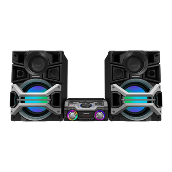
Speaker System
SB-MAX770PU
PSG1402010CE
PAGE
Advertisement
Table of Contents

Related Manuals for Panasonic SB-MAX770PU


Summary of Contents for Panasonic SB-MAX770PU
-
Page 1: Table Of Contents
3.1. Front Speakers --------------------------------------------10 4 Exploded View and Replacement Parts List -----------11 4.1. Cabinet Parts Location --------------------------------- 11 4.2. Packaging --------------------------------------------------12 4.3. Replacement Parts List ---------------------------------13 © Panasonic Corporation 2014, All rights reserved. Unauthorized copying and distribution is a violation of law. -
Page 2: Specifications
1 Specifications Front Speakers Type 4 way, 4 speaker system (Bass reflex) Speaker(s) Super Woofer (Low) 38 cm cone type Super Woofer (Medium Low) 20 cm cone type Woofer 10 cm cone type Tweeter 6 cm cone type 3 Ω (High), 3 Ω (Medium Low), Impedance 5 Ω... -
Page 3: Disassembly And Assembly Instructions
2 Disassembly and Assembly Instructions Caution Note: • This section describes procedures for checking the operation and replacing the main components. • For reassembly after operation checks or replacement, reverse the respective procedures. • Special reassembly procedures are described only when required. •... -
Page 4: Disassembly Of Upper Front Panel Assembly
2.1. Disassembly of Upper Front Step 4 : Insert two flathead screwdriver at the sides of the boss and apply light force to push out the Upper Front Panel Assem- Panel Assembly bly by sequence (1-7) shown. Caution : Do not exert too much force as it may damage the Upper Front Panel Assembly. -
Page 5: Disassembly Of Tweeter Speaker (Sp1)
2.2. Disassembly Tweeter 2.3. Disassembly of Full Range Speaker (SP1) Speaker (SP2) • Refer to “Disassembly of Upper Front Panel Assembly”. • Refer to “Disassembly of Upper Front Panel Assembly”. Step 1 : Remove 4 screws. Step 1 : Remove 4 screws. Step 2 : Remove the Tweeter Speaker (SP1). -
Page 6: Disassembly Of Full Range Speaker (Sp3)
2.4. Disassembly of Full Range 2.5. Disassembly of Lower Front Speaker (SP3) Panel Assembly • Refer to “Disassembly of Upper Front Panel Assembly”. • Refer to “Disassembly of Upper Front Panel Assembly”. Step 1 : Remove 4 screws. Step 1 : Remove 4 screws. Step 2 : Remove the Corner Guard. - Page 7 Step 4 : Insert two flathead screwdriver at the sides of the boss Step 6 : Detach the 4P Wire Socket. and apply light force to push out the Lower Front Panel Assem- Step 7 : Remove the Lower Front Panel Assembly. bly by sequence (1-9) shown.
-
Page 8: Disassembly Of Woofer Speaker (Sp4)
2.6. Disassembly Woofer 2.7. Disassembly of Lighting Wire Speaker (SP4) P.C.B. Assembly • Refer to “Disassembly of Upper Front Panel Assembly”. • Refer to “Disassembly of Upper Front Panel Assembly”. • Refer to “Disassembly of Lower Front Panel Assembly”. • Refer to “Disassembly of Lower Front Panel Assembly”. Step 1 : Remove 8 screws. - Page 9 Step 4 : Release the 4P wire from the slots. Caution : During assembling, ensure that the 4P wire is properly inserted into the slot. Step 5 : Remove 2 screws. Step 6 : Remove the Lighting Wire P.C.B. Assembly.
-
Page 10: Wiring Connection Diagram
3 Wiring Connection Diagram 3.1. Front Speakers... -
Page 11: Exploded View And Replacement Parts List
4 Exploded View and Replacement Parts List 4.1. Cabinet Parts Location 17 17 13-2 (LIGHTING P.C.B.) 13-1 SB-MAX700PUK CABINET DRAWING... -
Page 12: Packaging
4.2. Packaging SB-MAX770PU SB-MAX770PU POLYFOAM (TOP) POLYFOAM (BOTTOM) SB-MAX770PUK PACKAGING DRAWING... -
Page 13: Replacement Parts List
4.3. Replacement Parts List 4.3.1. Front Speakers Safety Ref. No. Part No. Part Name & Qty Remarks Description XTB4+10GFJ SCREW RMF0600J HIMELON Safety Ref. No. Part No. Part Name & Qty Remarks RMF0600C HIMELON Description RMF0600 HIMELON RMF0600A HIMELON CABINET & CHAS- RMQ2070 HIMELON RKA0072-KJ...