Advertisement
Quick Links
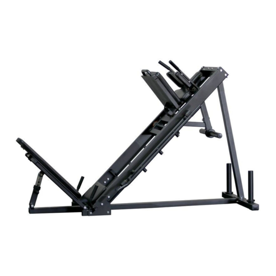
LEG PRESS HACK SQUAT MACHINE
LEGPRS1-LEGPRS2-LEGPRS3
400698
Operator's Manual
Read the Operator's Manual entirely. When you see this
symbol, the subsequent instructions and warnings are
serious follow without exception. Your life and the lives
of others depend on it!
Advertisement

Related Manuals for Titan Fitness LEGPRS1


Summary of Contents for Titan Fitness LEGPRS1
- Page 1 LEG PRESS HACK SQUAT MACHINE LEGPRS1-LEGPRS2-LEGPRS3 400698 Operator’s Manual Read the Operator’s Manual entirely. When you see this symbol, the subsequent instructions and warnings are serious follow without exception. Your life and the lives of others depend on it!
- Page 2 PARTS DIAGRAM / EXPLODED VIEW DESCRIPTION DESCRIPTION REAR BASE FRAME (38) 2&3 BUMPER 77*47.5*13 REAR UPRIGHT FRAME (39) STOPPER 30*70*20 MIDDLE BASE FRAME (40) 2&3 END CAP RIGHT CONNECTING FRAME (41) BUSHING LEFT CONNECTING FRAME (42) KNOB UPPER CROSS GRAME (43) BASE MAT ADJUSTING FRAME...
- Page 3 (12) PEDAL (49) STOPPER 32*25*50 (13) R HANDLEBAR FRAME (50) RUBBER BUMPER 38*7*15 (14) L HANDLEBAR FRAME (51) FRONT HANDLE SLEEVE (15) R LIMITED FRAME (52) END CAP (16) L LIMITED FRAME (53) END CAP F32*2 (17) R SIDE FRAME (54) SOCKET CAO SCREW M6*10 (18)
- Page 4 ASSEMBLY INSTRUCTIONS STEP 1 Assemble RIGHT & LEFT CONNECTING FRAME (4 & 5) and MIDDLE BASE FRAME (3) using FLAT WASHER Φ11*Φ20*2 (55), NUT M10 (57) and HEX BOLT M10*95 (59). Install REAR UPRIGHT FRAME (2) and MIDDLE BASE FRAME (3) to REAR BASE FRAME (1), using FLAT WASHER Φ11*Φ20*2 (55), NUT M10 (57), HEX BOLT M10*95 (59), and HEX BOLT M10*25 (60).
- Page 5 ASSEMBLY INSTRUCTIONS STEP 2 Assemble RIGHT &LEFT SIDE HANDLE FRAME (22 & 23) and RIGHT & LEFT CONNECTING FRAME (4 & 5) using FLAT WASHER Φ11*Φ20*2 (55), NUT M10 (57) and HEX BOLT M10*70 (64). Assemble UPPER CROSS FRAME (6) and REAR UPRIGHT FRAME (2), using FLAT WASHER Φ11*Φ20*2 (55), NUT M10 (57), HEX BOLT M10*120 (63), and HEX BOLT M10*70 (64).
- Page 6 ASSEMBLY INSTRUCTIONS STEP 3 Assemble RIGHT & LEFT SIDE FRAME (17 & 18), SEAT PAD CONNECT FRAME (20) and UPPER CROSS FRAME (6) using FLAT WASHER Φ11*Φ20*2 (55), NUT M10 (57), HEX BOLT M10*25 (60), HEX BOLT M10*75 (66), and HEX BOLT M10*120 (63). THEN TIGHTEN ALL BOLTS...
- Page 7 ASSEMBLY INSTRUCTIONS STEP 4 The RIGHT & LEFT LIMITED FRAME (15 & 16) through the hole on RIGHT & LEFT SIDE FRAME (17 & 18). Then insert it into the FIXING FRAME (37) using FLAT WASHER Φ11*Φ20*2 (55), and HEX BOLT M10*15 (61).
- Page 8 ASSEMBLY INSTRUCTIONS STEP 5 Assemble RIGHT & LEFT HANDLEBAR FRAME (13 & 14), and SLIDING FRAME (21), using FLAT WASHER Φ11*Φ20*2 (55), HEX BOLT M10*25 (60), and HEX BOLT M10*75 (66). THEN TIGHTEN ALL BOLTS.
- Page 9 ASSEMBLY INSTRUCTIONS STEP 6 Assemble DIAGONAL BRACING (10), WEIGHT PLATE HOLDER (11), and SLIDING FRAME (21) using FLAT WASHER Φ11*Φ20*2 (55), NUT M10 (57), HEX BOLT M10*15 (61), and HEX BOLT M10*30 (65) as shown.
- Page 10 ASSEMBLY INSTRUCTIONS STEP 7 Install BACK PAD FRAME (8) TO MIDDLE BASE FRAME (3) using FLAT WASHER Φ13.5*Φ24*2.5 (56), NUT M12 (58), and HEX BOLT M12*65 (68). PLEASE TIGHTEN ALL BOLTS.
- Page 11 ASSEMBLY INSTRUCTIONS STEP 8 Assemble WAIST PAD (27), BACK PAD (28), SHOULDER PAD (29), SEAT PAD (30) and BACK PAD (31) as shown using FLAT WASHER Φ11*Φ20*2 (55), HEX BOLT M10*25 (60), and PAN HEAD, HEX BOLT M10*55 (73). THEN TIGHTEN ALL BOLTS.
- Page 12 ACKNOWLEDGEMENT OF RISK AND RELEASE OF LIABILITY The use of any equipment, including this one, involves the potential risk of injury. Apart from any warranty claim that might be presented for a claimed defect in material or workmanship of the product, you accept and assume full responsibility for any and all injuries, damages (both economic and non-economic), and losses of any type, which may occur, and you fully and forever release and discharge Titan, its insurers, employees, officers, directors, associates, and agents from any and all claims, demands, damages,...
- Page 13 NEED HELP? CONTACT US FIRST. 1-888-410-1503 info@titan.fitness www.titan.fitness © 2021 Titan Brands...
Need help?
Do you have a question about the LEGPRS1 and is the answer not in the manual?
Questions and answers