Table of Contents
Advertisement
Quick Links
Advertisement
Table of Contents

Related Manuals for Fluke RUSKA 2465A-754


Summary of Contents for Fluke RUSKA 2465A-754
- Page 1 RUSKA 2465A-754 Gas Piston Gauge Users Manual PN 3952328 November 2010 © 2010 Fluke Corporation. All rights reserved. Printed in USA. Specifications are subject to change without notice. All product names are trademarks of their respective companies.
- Page 2 Fluke authorized resellers shall extend this warranty on new and unused products to end-user customers only but have no authority to extend a greater or different warranty on behalf of Fluke. Warranty support is available only if product is purchased through a Fluke authorized sales outlet or Buyer has paid the applicable international price.
-
Page 3: Table Of Contents
Pressure ....................1-3 Power Requirements ................1-3 General Piston Pressure Gauge Considerations ......2-1 Introduction.................... 2-1 How to Contact Fluke ................2-1 Safety Information ................. 2-1 Symbols Used in this Manual ..............2-2 Types of Piston Pressure Gauges............2-3 Calculations................... 2-5 Measurement of Pressure with the Piston Pressure Gauge.... - Page 4 RUSKA 2465A-754 Users Manual Introduction.................... 4-1 Operation ..................... 5-1 Precautions ................... 5-1 General....................5-2 Low Range Piston Assembly..............5-2 Mid Range Piston Assembly..............5-6 35 Bar Assembly ................... 5-8 High Range Piston Assembly ..............5-9 Establishing Gauge Pressures .............. 5-10 Gauge Pressures................
- Page 5 List of Tables Table Title Page 2-1. Symbols........................2-2...
- Page 6 RUSKA 2465A-754 Users Manual...
- Page 7 List of Figures Figure Title Page 2-1. Simple Cylinder ..................... 2-3 2-2. Re-Entrant Cylinder ....................2-3 2-3. Controlled Clearance Cylinder................2-3 2-4. Reference Plane Determination................2-8 2-5. Head Correction Measurement................2-9 3-1. Gas Piston Gauge - Top View................3-2 3-2. Gas Piston Gauge - Front View................
- Page 8 RUSKA 2465A-754 Users Manual...
-
Page 9: Specifications
Chapter 1 Specifications Low Range Piston Pressure Range (Model 2465) 1.4 to 172 kPa (0.2 to 25 psi) absolute, gauge or negative gauge Pressure Range (Model 2468) 1.4 to 345 kPa (0.2 to 50 psi) absolute, gauge or negative gauge Pressure Uncertainty Rating 0.0010% RDG (10 ppm) or 0.07 Pa (1.0E-05 psi), whichever is (2, 3) -
Page 10: Upper Mid Range Piston
RUSKA 2465A-754 Users Manual Upper Mid Range Piston Pressure Range (Model 2465) 14 to 3500 kPa (2 to 500 psi) absolute or gauge Pressure Range (Model 2468) 14 to 7000 kPa (2 to 1000 psi) absolute or gauge Pressure Uncertainty Rating 0.0026% RDG (26 ppm) or 2.8 Pa (4.0E-04 psi), whichever is... -
Page 11: Temperature Range
Specifications Temperature Range Temperature Range Operating 18 ºC to 28 ºC Storage -40 ºC to 70 ºC Humidity Range Operating 20% to 75% non-condensing Storage 0% to 90% non-condensing Pressure Medium Clean dry gas, Nitrogen or equivalent, regulated to a Pressure Compatible with each particular piston/cylinder assembly. - Page 12 RUSKA 2465A-754 Users Manual...
-
Page 13: General Piston Pressure Gauge Considerations
This manual contains operation and routine and preventive maintenance instructions for the RUSKA 2465A-754 Gas Piston Gauge manufactured by Fluke. How to Contact Fluke To order accessories, receive operating assistance, or get the location of the nearest Fluke distributor or Service Center, call: •... -
Page 14: Symbols Used In This Manual
515 PSIA With high range piston/cylinder: 1015 PSIA W Warning Do not use hydrocarbon lubricants. Use only Fluke supplied lubricant, unless otherwise specified in this manual. Always use replacement parts specified by Fluke. W Warning When any maintenance is performed, turn off power and remove power cord. -
Page 15: Types Of Piston Pressure Gauges
General Piston Pressure Gauge Considerations Types of Piston Pressure Gauges W Warning If the equipment is used in a manner not specified by the manufacturer, the protection provided by the equipment may be impaired. Types of Piston Pressure Gauges The piston pressure gauge is sometimes regarded as an absolute instrument because of the principle by which it measures pressure. - Page 16 RUSKA 2465A-754 Users Manual It can be shown that the effective area of the piston and cylinder assembly is the mean of the individual areas of the piston and of the cylinder; therefore as the pressure is increased, the cylinder expands and the effective area becomes greater. The rate of increase is usually, but not always, a linear function of the applied pressure.
-
Page 17: Calculations
General Piston Pressure Gauge Considerations Calculations • Temperature of the piston and cylinder. • Buoyant effect of the atmosphere upon the masses. • Hydraulic and gaseous pressure gradients within the apparatus. Calculations For a consolidation of these various corrections, see Appendix A of this manual. Appendix A contains a Pressure Calculation Worksheet (both SI and English units) with instructions. -
Page 18: Buoyant Effect Of The Air
RUSKA 2465A-754 Users Manual English and the International System of units. Corrections for local gravity can vary by as much as 0.5% thus it is very important to have a reliable value for the local acceleration of gravity. A gravity survey with an uncertainty better than 0.00001 m/s... -
Page 19: Temperature
General Piston Pressure Gauge Considerations Temperature Temperature Piston pressure gauges are temperature sensitive and must, therefore, be corrected to a common temperature datum. Variations in the indicated pressure resulting from changes in temperature arise from the change in effective area of the piston due to expansion or contractions caused by temperature changes. - Page 20 RUSKA 2465A-754 Users Manual glg02.bmp Figure 2-4. Reference Plane Determination When a pressure for the piston pressure gauge is calculated, the value obtained is valid at the reference plane. The pressure at any other plane in the system may be obtained by...
-
Page 21: Crossfloating
General Piston Pressure Gauge Considerations Crossfloating − Where: is the vertical distance between the reference plane of the Standard and the reference plane of the DUT (Device Under Test) s the density of the air is the density of the test media is the acceleration due to local gravity is the vertical distance from the mass loading location to the effective bottom of the piston. -
Page 22: Bibliography
RUSKA 2465A-754 Users Manual pressures, and the values of areas obtained are plotted against the nominal pressure for each point. A least-squares line is fitted to the plots as the best estimate value of the area at any pressure. There are two accepted methods for determining the balance of the two pressures. First, the sink rates can be observed and graphed using high sensitivity sensors. -
Page 23: Description
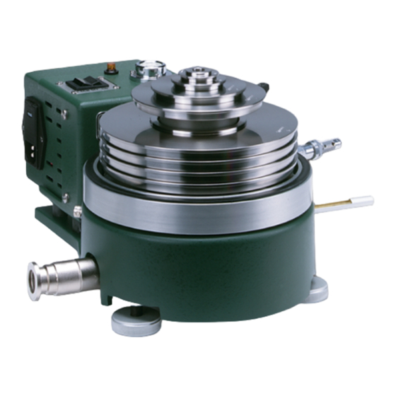
Description General Information The RUSKA 2465A-754 Gas Piston Gauge (see Figure 3-1 and 3-2), is a pneumatic pressure standard designed for the accurate generation and measurement of gas pressures to 1000 psi. This measurement is accomplished in the basic manner of using the... -
Page 24: Description Of The Mass Set
RUSKA 2456A-754 Users Manual Description of the Mass Set All masses of the Mass Set except sleeve mass, as supplied with this gauge are made of non-magnetic, austenitic (series 300) stainless steel. They are machined from rolled stock or forging, and the removal of any metal is performed in such a way as to maintain balance about the centerline. - Page 25 Description Description of the Mass Set ROTATION SENSOR PRESSURE INLET CONNECTOR CONNECTION glg05.eps Figure 3-2. Gas Piston Gauge - Front View...
- Page 26 RUSKA 2456A-754 Users Manual...
-
Page 27: Installation
Installation Introduction Numeric references are to drawing RUSKA 2465A-754, contained in Appendix B. The gauge should be installed in a room where the temperature is maintained between 18 ºC to 28 ºC. The actual temperature is not as important as the stability in temperature. - Page 28 RUSKA 2465A-754 Users Manual If the optional thermometer has been purchased, screw it into the 1/4 NPT hole in the right hand side of the 2465-12 Assembly. The graduated end of the thermometer will protrude through the hole in the right hand side of the base casting. Here too, a small amount of heat sink compound applied to the bulb of the thermometer will shorten the response time of the thermometer.
-
Page 29: Operation
Chapter 5 Operation Precautions 1. Do not over pressure the piston 2. Do not increase or decrease the pressure in the gauge rapidly. Always use a metering valve for flow control. If possible, hold a hand lightly on the weights to protect the piston from injury. -
Page 30: General
RUSKA 2465A-754 Users Manual General The cross-section drawing 2465-12 found in Appendix B will aid in identifying and assembling the following parts. The Filter (24-580), the Filter Retainer (2460-4-27), and the O-Ring (54-703-119) are placed in the Cylinder Housing (2460-65) in order listed. - Page 31 Operation Low Range Piston Assembly UPPER THRUST LOWER THRUST BEARING BEARING FILTER CYLINDER 2460-5-6 2460-4-25 24-580 FILTER RETAINER PISTON UPPER THRUST O-RING 2460-4-27 WASHER 54-703-119 2460-5-5 glg07.eps Figure 5-2. Parts Required For Low Range Piston Operation If the Low Range Piston Assembly is to be used, the lower thrust bearing (2460-4-25) is required.
- Page 32 RUSKA 2465A-754 Users Manual glg08.eps Figure 5-3. Removing Low Range Piston and Cylinder from Container - Step 1 glg09.eps Figure 5-4. Removing Low Range Piston and Cylinder from Container - Step 2...
- Page 33 Operation Low Range Piston Assembly glg10.eps Figure 5-5. Handling the Low Range Piston and Cylinder The Low Range Cylinder (2460-5-1) and Low Range Piston Assembly (2460-55) should then be placed in the gauge after being cleaned according to the instructions in Chapter 6. See Figure 5-6.
-
Page 34: Mid Range Piston Assembly
RUSKA 2465A-754 Users Manual glg12.eps Figure 5-7. Positioning the Upper Thrust Washer/Piston Retainer in the Cylinder Retaining Cap Recess Mid Range Piston Assembly Refer to Figures 5-8 , 5-9, 5-10 and also to drawing 2465-727 in Appendix B. 1. If the Mid Range Piston Assembly is to be used, the Lower Thrust Bearing (2460-4-25) mentioned in the preceding section must be left in the gauge with the Filter, Filter Retainer, and O-Ring. - Page 35 Operation Mid Range Piston Assembly LOWER THRUST PISTON/CYLINDER BEARING ASSEMBLY 2460-4-25 FILTER O-RING FILTER RETAINER UPPER CYLINDER 54-703-119 2460-4-27 SPACER 2460-70-2 glg13.eps Figure 5-8. Parts Required for Operation of the Mid Range Piston/Cylinder glg14.eps Figure 5-9. Mid Range Piston/Cylinder Assembly...
-
Page 36: 35 Bar Assembly
RUSKA 2465A-754 Users Manual PISTON UPPER THRUST CYLINDER BEARING 2460-21 RETAINING NUT (THRUST BLOCK) glg15.eps Figure 5-10. Retaining Nut and Bearing 35 Bar Assembly Refer to Figure 5-11 and also to drawing 2465-730A in Appendix B. LOWER THRUST BEARING BEARING... -
Page 37: High Range Piston Assembly
Operation High Range Piston Assembly Next, assemble the Piston & Cylinder as follows. 2. All O-Rings should be lubricated with DuPont Krytox 240 AA Grease (45-339) before installation. All excess lubricant should be wiped off, leaving only a slight film. 3. -
Page 38: Establishing Gauge Pressures
RUSKA 2465A-754 Users Manual The High Range Piston and Cylinder can be installed as follows. 1. The Filter, Filter Retainer, and O-Ring should be in the gauge, as they were in Chapter 5, General. 2. Next, insert the Cylinder Container (2460-6-1) and the piston and cylinder after they... -
Page 39: Maintenance Of The Gauge
Operation Maintenance of the Gauge A thermometer well is provided on the right hand side of the gage base. If a glass thermometer is preferred, one is available as an accessory under part number 2465-6.A PRT (RTD) well is provided on the back left side of the gauge base. Either of these methods may be used to determine gauge temperature. - Page 40 RUSKA 2465A-754 Users Manual Should it ever become necessary to replace the power fuses, the fuse holders are located in the power-in receptacle on the side of the Motor Case Assembly (2465-15). These fuse holders are located inside the cavity above the three power receptacle prongs.
-
Page 41: Piston/Cylinder Cleaning Instructions
Chapter 6 Piston/Cylinder Cleaning Instructions General Information and Preparation When it is necessary to clean the Piston/Cylinder Assembly, the Piston Pressure Gauge must be partially disassembled and some of the components set aside until later. Upon removal of the internal components, a degree of risk is involved because of the possibility of exposing the parts to harmful dirt, corrosive fingerprints, and being dropped to the table or floor. -
Page 42: Functional Testing Of Piston/Cylinder Assemblies
RUSKA 2465A-754 Users Manual Being forewarned of the hazards, the technician should wipe the bench and all instrument surfaces in the vicinity of the Piston Pressure Gauge before starting disassembly operations. A wad of Kim-Wipes slightly wetted with a solvent, such as high grade alcohol or acetone will help pick up particles that invariably accumulate near the gauge. - Page 43 Piston/Cylinder Cleaning Instructions Cleaning the Low Range Piston/Cylinder Assembly glg18.eps Figure 6-1. Materials for Cleaning the Low Range Piston/Cylinder Prepare a clean work area near a running tap water source. Prepare several sets of folded wipers as shown in Figures 6-2, 6-3 and 6-4. glg19.eps Figure 6-2.
- Page 44 RUSKA 2465A-754 Users Manual glg20.eps Figure 6-3. Preparing the Kimwipes - Step 2 glg21.eps Figure 6-4. Preparing the Kimwipes - Step 3...
- Page 45 Piston/Cylinder Cleaning Instructions Cleaning the Low Range Piston/Cylinder Assembly Two wipers can be folded together for wiping the outside of the piston and cylinder. A single folded wiper can be inserted into, then wrapped around, the cleaning tool for cleaning the bore of the cylinder. See Figures 6-5 and 6-6. 1.
-
Page 46: Mid Range Piston/Cylinder
RUSKA 2465A-754 Users Manual 3. Scrub the bore of the cylinder using a soft bottle brush, Cashmere Bouquet soap and warm tap water. 4. Rinse thoroughly and dry immediately using the pre-folded wipers wrapped around the cleaning tool. Set the cylinder aside and cover with a clean dry wiper. - Page 47 Piston/Cylinder Cleaning Instructions Mid Range Piston/Cylinder glg24.eps Figure 6-7. Materials for Cleaning the Mid Range Piston/Cylinder 1. Prepare a clean work area near a running tap water source. Prepare several sets of folded wipers as shown in Figures 6-2, 6-3, and 6-4. 2.
-
Page 48: Cleaning The 35 Bar Piston/Cylinder Assembly
RUSKA 2465A-754 Users Manual 5. Scrub the bore of the cylinder using a soft bottle brush, Cashmere Bouquet soap and warm tap water. 6. Rinse thoroughly and dry immediately using the pre-folded wipers wrapped around the cleaning tool. Set the cylinder aside and cover with a clean dry wiper. - Page 49 Piston/Cylinder Cleaning Instructions Cleaning the 35 Bar Piston/Cylinder Assembly glg26.eps Figure 6-9. Materials for Cleaning the High Range Piston Cylinder 1. Prepare a clean work area near a running tap water source. Prepare several sets of folded wipers as shown in Figures 6-2, 6-3 and 6-4. Two wipers can be folded together for wiping the outside of the piston and cylinder.
- Page 50 RUSKA 2465A-754 Users Manual glg28.eps Figure 6-11. Preparing Kimwipes for Cleaning the High Range Cylinder - Step 2 glg29.eps Figure 6-12. Preparing Kimwipes for Cleaning the High Range Cylinder - Step 3 4. Scrub the bore of the cylinder using a soft bottle brush, Cashmere Bouquet soap and warm tap water.
-
Page 51: Cleaning The High Range Piston/Cylinder Assembly
Piston/Cylinder Cleaning Instructions Cleaning the High Range Piston/Cylinder Assembly 7. Clean the thrust bearing, cylinder container and upper retaining ring using solvent soaked wipers and set aside. 8. Inspect the O-rings for any sign of damage, replace as necessary. 9. Apply a slight amount of lubricant to the O-rings and wipe off any excess. 10. - Page 52 RUSKA 2465A-754 Users Manual 8. Clean the thrust bearing, cylinder container and upper retaining ring using solvent soaked wipers and set aside. 9. Inspect the O-rings for any sign of damage, replace as necessary. 10. Apply a slight amount of lubricant to the O-rings and wipe off any excess.
- Page 53 Piston/Cylinder Cleaning Instructions Cleaning the High Range Piston/Cylinder Assembly 11. Place the cylinder upright (narrow neck upward) on the work area. Carefully insert the piston into the top of the cylinder and allow it to sink freely into the cylinder. Do not force the piston into the cylinder or it may be damaged.
- Page 54 RUSKA 2465A-754 Users Manual 6-14...
-
Page 55: A Calculations
Appendix A Calculations Explanation of Pressure Calculation Worksheet (Pages A9 and A11) These tables may be used with gas and hydraulic piston pressure gauges that are operated with an atmospheric reference or vacuum reference. represents the pressure at the piston reference gauge level, represents the pressure desired at the device under test, is the head pressure created by the pressure medium and the difference in height between the piston pressure gauge and the device under test. - Page 56 RUSKA 2465A-754 Users Manual All of the calculations will be performed to this expected temperature . A final trim would be calculated to adjust the piston gauge to the temperature of the piston at the time of the actual measurement. This correction is calculated in the last column of the worksheet.
- Page 57 Calculations Explanation of Pressure Calculation Worksheet The apparent mass (Column 9) is obtained from: where: apparent mass; record in Column 9 force required on piston; as found in Column 8 multiplier which was determined by previous equation For SI Units ρ...
- Page 58 F. Column 2 is the mass density of the pressure medium being used in the piston pressure gauge system. For hydraulic piston pressure gauges, this number can be considered constant for all pressures. Fluke Calibration has two types of hydraulic piston fluids available. One is a Spinesstic 22™ part number 55-500 which has a density of 0.031 pounds per cubic inch (858 kilograms per cubic meter).
- Page 59 "remainder", recorded in Column 11, is realized with the Trim Mass set provided with all RUSKA Mass Sets. The Fluke supplied Trim Mass Sets are defined as Class 3, Type 1 (per ASTM E617, formerly Class S1 per NBS Cir. 547).
- Page 60 RUSKA 2465A-754 Users Manual EQUATION A-4 Air Density Air Density (ρ ) in units of g/cm , is calculated as follows; ρ − − 5315 0004646 4990221 where: P = Barometric Pressure, (mmHg) = Air Temperature, (ºC) U = Relative Humidity, (%RH)
- Page 61 Calculations Air Density Nitrogen Density - SI Units (6.9 MPa to 100 MPa) To calculate the density of Nitrogen at pressures from 6.9 MPa gauge to 100 MPa, use the following equation; − DENSITY 055087 where; PRESSURE in MPa absolute (if P is in gauge, convert it to MPa absolute 101325 by adding barometric pressure, e.g.
- Page 62 RUSKA 2465A-754 Users Manual Conversion Factors Table A-1. Conversion Factors To Convert From Multiply By 1.450377 X 10 6894.76 145.0377 6.89476 X 10 where pascal megapascal newton meter pounds per square inch...
-
Page 67: B Drawings And Bills Of Materials
Appendix B Drawings and Bills of Materials Drawings and Bills of Material This section contains drawings and bills of material for the Gas Piston Gauge, RUSKA 2465A-754. - Page 68 RUSKA 2465A-754 Users Manual glg32.bmp Figure B-1. P/C ASSY. (LR) CAL'D...
- Page 69 Drawings and Bills of Materials Drawings and Bills of Material glg33.bmp Figure B-2. P/C ASSY. (LR)
- Page 70 RUSKA 2465A-754 Users Manual glg34.bmp Figure B-3. P/C ASSY W/O CLEANING KIT...
- Page 71 Drawings and Bills of Materials Drawings and Bills of Material glg35.bmp Figure B-4. PISTON/CYL ASSY...
- Page 72 RUSKA 2465A-754 Users Manual glg36.bmp Figure B-5. PC ASSY (MHR) W/O CLEANING KIT...
- Page 73 Drawings and Bills of Materials Drawings and Bills of Material glg37.bmp Figure B-6. PIST/CYL ASSY...
- Page 74 RUSKA 2465A-754 Users Manual glg38.bmp Figure B-7. P/C ASSY (HR) CAL'D W/O CLEANING KIT...
- Page 75 Drawings and Bills of Materials Drawings and Bills of Material glg39.bmp Figure B-8. P/C ASSY...
- Page 76 O-RING VITON 9/16 X 3/32 3872923 2460-6-156 RETAINING CLIP * See Page B-9 Fluke recommends the unit is returned to the factory if items 7, 8, 9, or 10 need replacement. glg46.bmp Figure B-9. RUSKA 2465A-754 - Exterior View B-10...
- Page 77 Drawings and Bills of Materials Drawings and Bills of Material glg41.bmp Figure B-10. RUSKA 2465A-754 - Interior View B-11...
- Page 78 RUSKA 2465A-754 Users Manual Table B-2. 2465A-23, Lines & Fitting Kit Fluke Item Description 3862830 25-364, FTG NPL CAJ 2HLN 1/8X1-1/2 SS-2-HLN-1.50 3862990 25-434, FTG 1/8NPTMX1/4TBG SS-400-1-2 3863003 25-438, FTG M CON 1/4 NPTX1/4TBG SWAGELOK ONLY 3134815 101806, ADPT, BR, 6T X 4NPTM...
- Page 79 Drawings and Bills of Materials Drawings and Bills of Material glg42.bmp Figure B-11. Kit, Lines and Fittings B-13...
- Page 80 RUSKA 2465A-754 Users Manual glg43.bmp Figure B-12. 2465A-23 B-14...
Need help?
Do you have a question about the RUSKA 2465A-754 and is the answer not in the manual?
Questions and answers