Table of Contents
Advertisement
Sep. 2016
Table of Contents
Cautionary Notes ..............................................................2
Specifications .....................................................................3
Location of Controls (Top)...............................................4
Location of Controls Parts List (Top) .............................4
Location of Controls (Rear)..............................................5
Location of Controls Parts List (Rear) ............................5
Exploded View ..................................................................6
Exploded View Parts List.................................................7
Exploded View (Fig. A)....................................................8
Exploded View Parts List (Fig. A) ..................................9
Plain View ........................................................................10
Disassembly Procedure ..................................................11
Copyright © 2016 Roland Corporation
All rights reserved. No part of this publication may be reproduced in any form without the written permission
of Roland Corporation.
Block Diagram/Wiring Diagram..................................12
Parts List ...........................................................................13
Virus Check ......................................................................15
Verifying the Version......................................................15
Data Backup and Restore Operations ..........................15
Performing a Factory Reset............................................15
System Update Procedure..............................................16
Test Mode .........................................................................16
Circuit Board (Main, Exp Pedal Board) .......................22
Circuit Diagram (Main Board: 1/3)..............................24
Circuit Diagram (Main Board: 2/3)..............................26
Circuit Diagram (Main, Exp Pedal Board: 3/3) ..........28
Revise Information
Dec. 7, 2016
Nov. 17, 2016
Mar. 24, 2017
17057067E0
SERVICE NOTES
Issued by RJA
p. 20
Corrected an error.
p. 20
Added a test item.
p. 20
Added a caution.
GT-1
CC-KWS
Advertisement
Table of Contents

Related Manuals for Boss GT-1


Summary of Contents for Boss GT-1
-
Page 1: Table Of Contents
Sep. 2016 GT-1 SERVICE NOTES Issued by RJA Table of Contents Cautionary Notes ..............2 Block Diagram/Wiring Diagram........12 Specifications ..............3 Parts List ................13 Location of Controls (Top)..........4 Virus Check ..............15 Location of Controls Parts List (Top) ......4 Verifying the Version............15 Location of Controls (Rear)..........5 Data Backup and Restore Operations ......15... -
Page 2: Cautionary Notes
Sep. 2016 GT-1 Cautionary Notes Before beginning the procedure, please read through this document. The matters described may differ according to the model. Back Up User Data! User data may be lost during the course of the procedure. Refer to Data Backup and Restore Operations (p. -
Page 3: Specifications
* AF method (Adaptive Focus method) is a proprietary method from Roland & AUX IN jack: Stereo miniature phone type BOSS that vastly improves the signal-to-noise (SN) ratio of the AD and DA converters. USB COMPUTER port: USB type B... -
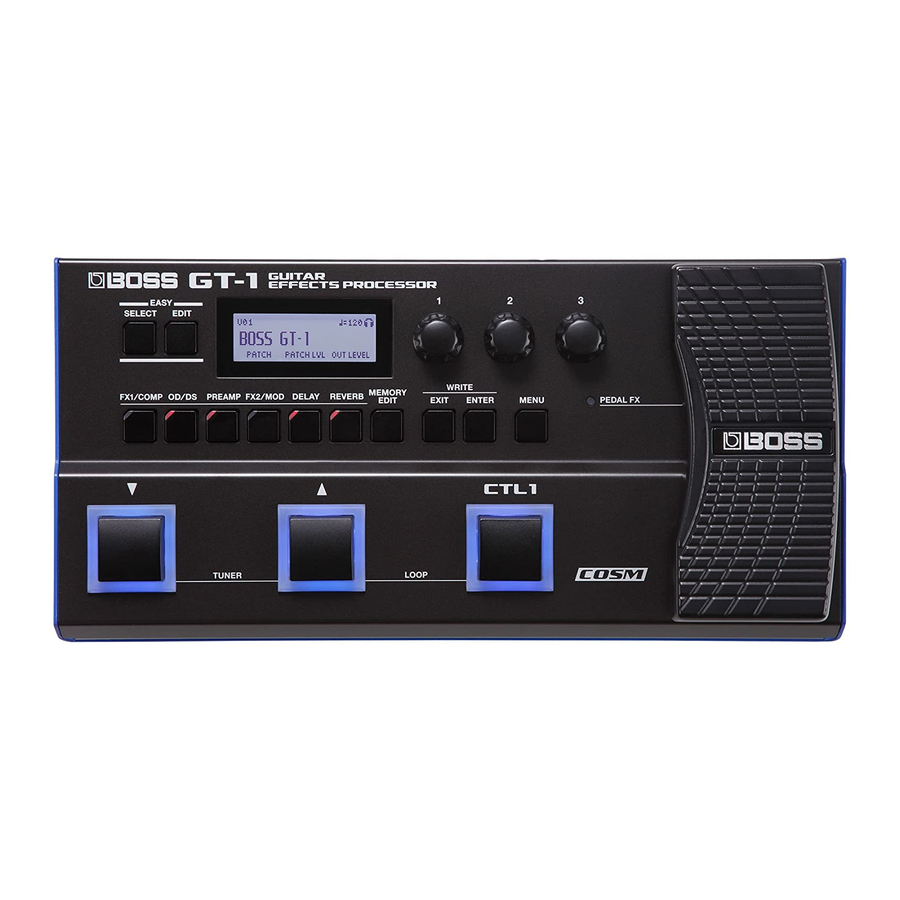
Page 4: Location Of Controls (Top)
Sep. 2016 GT-1 Location of Controls (Top) fig.panel-top.eps Location of Controls Parts List (Top) Part Code Part Name Description Q’ty 5100051758 KEY UNIT 5100051446 SWITCH EVPAWCD2A 5100051759 DISPLAY COVER 5100053348 QFG13232-30-PTDSOS-R 5100051760 DISPLAY CUSHION 5100051761 R-KNOB ******** attached to VR... -
Page 5: Location Of Controls (Rear)
Sep. 2016 GT-1 Location of Controls (Rear) fig.panel-rear.eps Location of Controls Parts List (Rear) Part Code Part Name Description Q’ty 02897334 6.5MM JACK HTJ-064-10D 5100028016 3.5MM JACK HTJ-035-10ABPP1 02341712 6.5MM JACK HTJ-064-10I(F3449106R0) 02341645 6.5MM JACK HTJ-064-04A 5100047083 USB CONNECTOR U7F04D-B1NB... -
Page 6: Exploded View
Sep. 2016 GT-1 Exploded View fig.bunkaizu-total.eps Refer to Fig. A... -
Page 7: Exploded View Parts List
Sep. 2016 GT-1 Exploded View Parts List Part Code Part Name Description Q’ty 5100051761 R-KNOB 5100051759 DISPLAY COVER 5100051748 TOP COVER 5100051760 DISPLAY CUSHION 5100051758 KEY UNIT 5100051751 SWITCH PEDAL 5100051753 SWITCH PEDAL SW SPRING 5100051766 SWITCH PEDAL TACT SPRING... -
Page 8: Exploded View (Fig. A)
Sep. 2016 GT-1 Exploded View (Fig. A) fig.bunkaizu-pedal.eps... -
Page 9: Exploded View Parts List (Fig. A)
Sep. 2016 GT-1 Exploded View Parts List (Fig. A) Part Code Part Name Description Q’ty 5100053334 BOSS BADGE 5100051754 VR PEDAL 5100051763 VR PEDAL CUSHION HEEL 5100051757 PIN STAY 5100051756 STAY 5100051442 MAIN BOARD ASSY * This unit includes the following parts. -
Page 10: Plain View
Sep. 2016 GT-1 Plain View fig.heimen.eps View 1 View 2 View 1 Part Code Part Name Description Q’ty 40011278 SCREW 3X8 BINDING TAPTITE P FE ZC 40012867 SCREW M3X8 PAN MACHINE W/SW+PW ZC View 2 Part Code Part Name Description Q’ty... -
Page 11: Disassembly Procedure
Sep. 2016 GT-1 Disassembly Procedure Remove the battery cover and take out the battery. Remove the screws (x 4) in the battery case. Detach the pedal. Remove the knobs (x 3) and VR nuts (x 3). Remove all screws (x 9) on the bottom. -
Page 12: Block Diagram/Wiring Diagram
Sep. 2016 GT-1 Block Diagram/Wiring Diagram fig.block.eps MAIN BOARD MUTE- OUTPU MUTE- OUTPU De-Emphassis Pre-Emphassis +5dB -8.16dB +3.3dB IC7A IC7A IC6A LOUT MUTE- BUFF INPUT BUFF BUFF BUFF PHONE +23.52dB ADDA IC7B IC7B IC6B Power ON : GND MUTE- ROUT... -
Page 13: Parts List
Sep. 2016 GT-1 Parts List fig.-part1-e.eps Due to one or more of the following reasons, parts with parts code ******** cannot be supplied Safety Precautions: as service parts. The parts marked have safety-related characteristics. Use • Supply is prohibited due to copyright restrictions. - Page 14 Sep. 2016 GT-1 MISCELLANEOUS 5100053383 BATTERY TERMINAL 5100053384 BATTERY TERMINAL 5100047009 BATTERY TERMINAL ± 5100053334 BOSS BADGE 5100051759 DISPLAY COVER 5100051765 RUBBER FOOT 5100053354 SHIELD COVER 5100018712 JACK SHIELD 5100051760 DISPLAY CUSHION 5100051762 VR PEDAL CUSHION 5100051763 VR PEDAL CUSHION...
-
Page 15: Virus Check
Set the track 2 in standby for recording and start recording and playback. The SysEx data on step 3 is sent to the GT-1, and then the GT-1 which received this data sends the system setting and all patch data (U01 to U99) to the MIDI sequence program. -
Page 16: System Update Procedure
• 1/4-inch stereo phone plug • Miniature stereo phone plug Hold down EXIT and connect a dummy plug to the INPUT jack. When GT-1 Updater appears on the screen of the GT-1, release your • Current-consumption measurement tool fingers. fig.check-cable.eps Connect the computer to the USB COMPUTER connector. - Page 17 INPUT jack. Other test items can be carried out by the dummy plug. This measures the current consumption. When the BOSS logo appears on the display, release your fingers. Entering the Test Mode displays the TEST MENU. Use the current-consumption measurement tool to connect the AC fig.test-0.eps...
- Page 18 Sep. 2016 GT-1 4. JACK SW 7. LCD/ENCODER This verifies the sensing operation of jacks. This verifies the display of the LCD screen. Connect the 1/4-inch stereo phone plug to the CTL2,3/EXP2 jack and the In the TEST MENU, select 7. LCD/ENCODER and press ENTER.
- Page 19 Sep. 2016 GT-1 8. INTERNAL EXP1 (CALIBRATION) 12. NOISE This performs calibration for the pedal of the unit. This measures residual noise. In the TEST MENU, select 8. INTERNAL EXP1 and press ENTER. Connect the 1/4-inch mono phone plug with 47 kΩ load resistor to the INPUT jack and enter the Test Mode.
- Page 20 Sep. 2016 GT-1 Input Test (AFAD) AUX Test 21. Connect the oscilloscope to the OUTPUT L/MONO and R jacks. Input a signal like the following to the INPUT jack. INPUT: 200-Hz sine wave at 0.218 Vpp (-20 dBm) 22. Connect the signal generator to the AUX IN jack (L, R) and input signals like the following.
- Page 21 Sep. 2016 GT-1...
-
Page 22: Circuit Board (Main, Exp Pedal Board)
Sep. 2016 GT-1 Circuit Board (Main, Exp Pedal Board) fig.b-main-1.eps... - Page 23 Sep. 2016 GT-1 fig.b-main-2.eps...
-
Page 24: Circuit Diagram (Main Board: 1/3)
Sep. 2016 GT-1 Circuit Diagram (Main Board: 1/3) fig.d-main-1.eps@L... - Page 25 Sep. 2016 GT-1 fig.d-main-1.eps@R...
-
Page 26: Circuit Diagram (Main Board: 2/3)
Sep. 2016 GT-1 Circuit Diagram (Main Board: 2/3) fig.d-main-2.eps@L... - Page 27 Sep. 2016 GT-1 fig.d-main-2.eps@R...
-
Page 28: Circuit Diagram (Main, Exp Pedal Board: 3/3)
Sep. 2016 GT-1 Circuit Diagram (Main, Exp Pedal Board: 3/3) fig.d-main-3.eps@L... - Page 29 Sep. 2016 GT-1 fig.d-main-3.eps@R...
Need help?
Do you have a question about the GT-1 and is the answer not in the manual?
Questions and answers