
Subscribe to Our Youtube Channel
Related Manuals for PMI Vision

Summary of Contents for PMI Vision
- Page 1 Vision™ Power Quality Recorder User’s Manual Power Monitors, Inc. Vision™ User’s Manual...
- Page 3 Vision™ Power Quality Recorder User’s Manual...
- Page 4 ©2009 Power Monitors, Inc. All Rights Reserved In no event shall the copyright owner or contributors be liable for any direct, indirect, incidental, special, exemplary, or consequential damages (including but not limited to, procurement of substitute goods or services). In no event shall the copyright owner or contributors be liable for any business interruption or loss of use, data, or profits however caused.
-
Page 5: Power Monitors, Inc
DEVICE AND THE SOFTWARE. THE SOFTWARE AND ASSOCIATED SOFTWARE DOCUMENTATION ARE PROPRIETARY AND COPYRIGHTED WORKS OWNED BY PMI OR ITS LICENSORS AND CONTAIN CONFIDENTIAL AND PROPRIETARY INFORMATION OF PMI AND/OR THIRD PARTY LICENSORS. ANY USE OF OR ACCESS TO THE... - Page 6 TERMS AND CONDITIONS Power Monitors, Inc., a Virginia corporation (“PMI”), agrees to license to you, the company, organization or legal entity that will be using the Device (referred to herein as “You” or “Your,”) subject to and only upon Your acceptance of all of the terms and conditions of this End-user License Agreement (this “Agreement”), which acceptance shall be conclusively indicated by Your use of...
- Page 7 Purchase Order means, collectively, the purchase order(s), bill(s) of sale, and other document(s), instrument(s) or agreement(s) pursuant to which PMI sells the Device to You, or which otherwise govern or apply to your purchase of the Device from PMI. License Grant.
- Page 8 Software and the Documentation, not specifically granted to You hereunder will be, and are specifically and entirely reserved to, PMI and its licensors and other third parties owning rights in the Software (collectively, “Licensors”) and may be fully exploited by PMI and Licensors without regard to the extent to such rights may be competitive with this Agreement or the rights granted hereunder.
- Page 9 Confidentiality. You shall maintain (and You shall cause all of Your employees and agents to maintain) in strictest confidence and shall not, without the permission of PMI, disclose to any third parties, nor use for any purpose other than in connection with the permitted exercise of Your rights...
- Page 10 BREACH OF CONTRACT, BREACH OF EXPRESS OR IMPLIED WARRANTY, MISREPRESENTATION, NEGLIGENCE, STRICT LIABILITY, OR ANY OTHER LEGAL THEORY, EVEN IF PMI OR A PMI PARTY WAS ADVISED ABOUT THE POSSIBILITY OF SUCH LOSS OR DAMAGE. Limitation of Liability. IN NO EVENT SHALL PMI OR ANY...
- Page 11 You, except that, (i) if such termination occurs within two (2) years of the Effective Date, PMI shall refund all Fees (less any taxes) paid by You for the Device upon Your return of the Device to PMI; (ii) if ) anniversary of the Effective Date...
- Page 12 (a) if to PMI, to the address set forth in the preamble to this Agreement; and (b) if to You, to Your address set forth in the Purchase Order.
- Page 13 No Waiver. The failure of PMI to enforce any of the provisions hereof shall not be construed to be a waiver of the right of PMI thereafter to enforce such provisions. Severability. If any provision of this Agreement shall be invalid...
-
Page 14: Table Of Contents
Safety Information ................... 1 Safety Specifications..................1 Safety Issues ....................2 Glossary of Symbols ..................3 Contents of the Vision™ Package ..............5 Manual Updates ..................6 Equipment Handling..................6 Initial Inspection ..................6 ... - Page 15 Analyzing Data ..................... 66 Ethernet Communications with VisionPro™ Recorders ........67 PC and Laptop Communications with Vision™ Recorders ......69 Field PC Communications with Vision™ Recorders ........71 PDA Communications with the Vision™ Recorder .......... 73 ...
- Page 16 Interval Graphs ..................77 Daily Profiles .................... 82 Cycle Histograms ..................84 Minute Histograms ................... 87 Energy Usage ..................88 Significant Change ................... 89 Event Change ..................93 Power Outage ..................97 Flicker .......................
-
Page 17: Table Of Figures
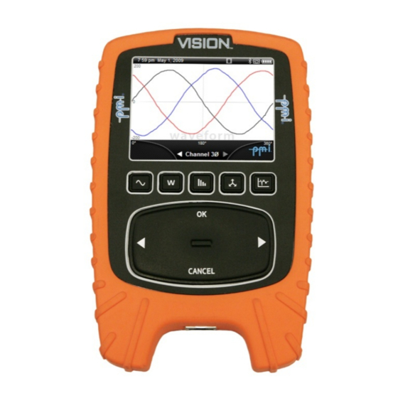
Figure 1 – The Vision™ Recorder............10 Figure 2 – Vision™ Models ..............12 Figure 3 – Vision™ USB Communications Cable ........14 Figure 4 – Vision™ Ethernet Communications Cable ......14 Figure 5 – TLAR Current Clamps............16 ... -
Page 18: Safety Information
EN/IEC 61010-1 second edition, 2001-02 With revisions through 6/2005. This Safety Notice has been included to emphasize the danger of hazardous voltages on the input connection leads of your Vision power quality recorder. USE EXTREME CAUTION WHEN CONNECTING your instrument. Hazardous potentials exist on voltage input leads and banana jacks. -
Page 19: Safety Issues
PMI flexible CTs and True Low-Ampere Reading (TLAR) CTs available for use with the Vision are manufactured with 600V rated integral cables, preventing accidental disconnection. Although the recorder has been designed and built to be as safe as possible, great care should be exercised at all times during operation and installation. -
Page 20: Glossary Of Symbols
Glossary of Symbols Below is a glossary of symbols that appear on the Vision. Please read this section carefully to familiarize yourself with the symbols and their meanings before installing or using the Vision. ® These symbols indicate ® Bluetooth... -
Page 22: Contents Of The Vision™ Package
• USB communications cable • 120VAC power adapter • Set of color coded banana plug voltage leads and dolphin clips – (5 leads for VisionPro and Vision, 4 leads for the VisionLite) • 12” Flex CTs • Flex CT current input adapter cable •... -
Page 23: Manual Updates
This manual may periodically be updated with new versions that could affect the connection information contained in this section. When purchasing a new Vision recorder, review the manual for that recorder, as information in manuals received with older Vision recorders may not pertain to your recorder. - Page 24 •...
-
Page 25: Introduction
Ethernet communications, high speed sampling transient capture, and viewing of all real-time and recorded data without disturbing or altering an in-progress recording session, Vision™ recorders are powerful tools for both on-site and remote power quality analysis. The Vision™ recorder features: •... - Page 26 IEEE 141 and IEEE 1453 (IEC 61000-4-15) flicker graphs and reports After reviewing this manual and using your Vision, please contact us with any questions about its operation, or with ideas for new features or products. We want you to be satisfied with this product, and your comments will help us continue to develop products that meet your needs for power quality measurement and analysis tools.
-
Page 27: Getting Started With The Vision
Since the Vision operates on an internal battery or external 120V power supply, it will not disrupt or alter the normal power source to which it is connected. -
Page 28: Available Models
With the software, you can create an array of graphs and reports, each of which provides useful, clearly presented power quality data. Available Models There are three available models of the Vision. The label on the front of the recorder identifies the model of the unit. ® •... -
Page 29: Available Inputs
Available Inputs Direct connections are supplied for 4 voltage and 4 current inputs on the VisionPro and Vision, and 3 voltage and 3 current inputs for the VisionLite. All voltage inputs are rated for 0 to 600VAC continuous (and ±5kV transient measurement on VisionPro). The maximum current that can be measured is dependent on the CT being used. -
Page 30: System Description
USB and Ethernet Communications A mini-USB connector is available on the right side of the Vision (under a protective rubber tab) for connection to your computer or the supplied AC power adapter using the included USB communications cable. -
Page 31: Figure 3 - Vision™ Usb Communications Cable
Figure 3 – Vision™ USB Communications Cable A standard RJ45 Ethernet jack is available on the bottom of the Vision housing for connecting the Vision to an Ethernet port. Figure 4 – Vision™ Ethernet Communications Cable Getting Started with the Vision™ •... -
Page 32: Bluetooth Wireless Communications
® Bluetooth Wireless Communications You may communicate with the Vision recorders from a laptop or desktop PC, select Palm PDAs, or a PMI Field PC equipped with ® Bluetooth wireless technology (VisionPro and Vision only). Refer ® to the appropriate software manual for detailed communications information and instructions. -
Page 33: Ultra Slim Flexible Cts
PMI has a wide selection of Flexible CTs that range in circumference from 12 to 48 inches and have ranges of 100, 1000, and 5000 Amps. All PMI flexible CTs are powered from the recorder - no external batteries are needed. -
Page 34: Voltage Clips
Voltage Clips PMI offers two types of voltage clips for your application. The dolphin style clips are standard with every recorder. Grabber style clips are optional at an additional cost. Figure 7 – Voltage Clips Getting Started with the Vision™ •... -
Page 35: Figure 8 - Vision™ Specifications
5 hrs, unit OFF/ON Significant Change 1000 records From USB 12 hrs, unit OFF Flicker 1000 records Implementation of new developments and product improvements may result in specification changes. Figure 8 – Vision™ Specifications Getting Started with the Vision™ •... -
Page 36: Connecting The Vision
5 hrs with the display backlight on continuously or 8 hrs with the display backlight turned off. The battery will charge from the 5V 2A PMI power adapter from a fully discharged state in approximately 5 hrs with the unit turned on or off. -
Page 37: Safety Considerations
Vision recorder. The required operating power can also be supplied from a standard USB port if the Vision backlight is turned off. If the Vision backlight is turned on, a slow reduction in internal battery charge will occur while connected to a USB port. -
Page 38: Environmental Considerations
There are two things to connect when installing the Vision: • CTs (Flex or TLARs) • Voltage measurement leads Installing the Vision Before connecting the voltage leads or current measurement CTs to the Vision, the recorder should either be turned OFF or placed Connecting the Vision™ •... - Page 39 (memory erased) prior to starting a new recording session. To place the Vision in the PAUSE mode, press one of the four real time function keys (Waveforms, Readings, Harmonics, or Vectors) to access the Perimeter Menu Screen (see Systems Settings Menus section for a description of this screen).
-
Page 40: Figure 9 - Vision™ Adapter Cable
CTs and voltage leads of the recorder. To connect the Flex CT or TLAR probes to the Vision, insert the 9- pin MALE connector of the CT output cable into the 9-pin FEMALE connector on the Vision current adapter cable and rotate the connector locking ring. - Page 41 CT range selection during recording. The Voltage Inputs The Vision power quality recorder can monitor voltage on three or four input channels, depending on the Vision model. Voltage leads rated for 600V CAT IV (1000V CAT III) are provided for each channel.
- Page 42 Connecting to different types of services When connecting the Vision power quality recorder, keep the following things in mind: • The banana jacks are color-coded by channel: Black - Channel 1, Red - Channel 2, Blue - Channel 3, Yellow - Channel 4, and White - Common.
-
Page 43: Figure 10 - Vision™ Hookup Diagrams
Figure 10 – Vision™ Hookup Diagrams Connecting the Vision™ •... -
Page 44: Disconnecting Voltage Leads And Cts
To place the Vision in the PAUSE mode, press one of the four real time function keys (Waveforms, Readings, Harmonics, or Vectors) to access the Perimeter Menu Screen. Scroll to the menu choice PAUSE and press the OK button on the scroll pad. -
Page 45: Usb Communications Cable
Vision recorder. The required operating power can also be supplied from a standard USB port if the Vision backlight is turned off. If the Vision backlight is turned on, a slow reduction in internal battery charge will occur while connected to a USB port. -
Page 46: Ethernet Communications Cable
Figure 12 – Ethernet Communications Cable Insert the Ethernet cable plug into the RJ45 jack located on the bottom of the Vision (VisionPro only). Insert the RJ-45 plug on the other end of the cable into a standard network port. Once connected ProVision can be used to connect to the recorder for remotely downloading data and initializing the Vision for recording. - Page 47 Connecting the Vision™ •...
-
Page 48: Operating The Vision
Operating the Vision™ Power Mode Control The Vision power control button is located on the right side of the enclosure. This button allows control of the three primary power operating modes, On, Off, and Suspend. When the Vision is turned OFF, press the power button to turn on the unit. -
Page 49: Suspend Mode
Press OK to place the unit in SUSPEND mode Suspend Mode Placing the Vision in Suspend mode will turn off the display backlight and place the unit in a low power mode of operation. The Vision will continue its current mode of operation (recording, or paused) while in Suspend mode. - Page 50 When viewing recorded data graphs and report screens, press OK to exit the screen and return to the Data Key Perimeter Menu Screen. Operating the Vision™ •...
-
Page 51: Display Icons
CANCEL key functions when viewing recorded graphs. Display Icons Individual display icons are provided on the Vision display toolbar at the top of the screen to indicate battery charge state, record or ® pause mode, the operating status of Bluetooth... -
Page 52: Battery Charge
When a valid wireless connection is established between the ® Vision and a PC, laptop, PDA, or PMI Field PC, a white Bluetooth figure mark will appear on the menu bar. During a wireless connection, the Vision graphic display ®... -
Page 53: Memory Usage
A USB icon will appear on the menu bar to indicate a connection to a USB port on another device. Demo Mode The demo icon will appear to indicate that the Vision is in demo mode. In this mode the Vision will display real time demonstration waveforms. -
Page 54: Battery Charge Led
Battery Charge LED A bi-color charge status LED is located on the right side of the Vision enclosure. An orange color indicates that the internal battery is charging. A green color indicates that the internal battery is fully charged. This LED will illuminate with the Vision turned on or off. -
Page 55: Waveforms Key
RIGHT > arrows on the scroll pad. The first screen provides a display of RMS voltage and current, and Voltage and Current distortion values (VTHD, ITHD). The second screen lists accumulated real, reactive, and apparent power - kWh, kVARh, Operating the Vision™ •... -
Page 56: Harmonics Key
– Voltage, Current, V&I, Turn Off Fundamental (turns off 60Hz component - automatically rescales the display to view individual harmonics), View All (displays all odd and even harmonics), Odd Only, and Even Only. Operating the Vision™ •... -
Page 57: Vectors Key
Use the Vectors key or the scroll pad feature to navigate between user choices inside the Perimeter Menu Screen (see SCROLL PAD and MAIN FUNCITON KEYS description above). Press OK on the scroll pad to make a menu selection. Operating the Vision™ •... -
Page 58: Viewing Recorded Data
Viewing Recorded Data Viewing Data While Recording The Vision will continue to record until placed in the PAUSE mode, or until the recorded data is downloaded to an external PC, even while viewing recorded information. When the DATA key is... - Page 59 Data Menu Screen Descriptions Summary The Vision Summary screen indicates the start and end times of the stored recording session, the selected current range, the type of Hookup used (Wye or Delta), and the selected initialization settings. Operating the Vision™ •...
- Page 60 The selected channel and plot will be listed at the top of the screen. CANCEL – toggles the function of the LEFT and RIGHT arrow keys (scroll through min-max-ave, or scroll between channels for the selected plot). Operating the Vision™ •...
- Page 61 Use the scroll pad to highlight an item in the list of available waveforms and press OK to select the waveform. Waveform Graph Operating the Vision™ •...
- Page 62 Use the scroll pad to highlight an item in the list of available waveforms and press OK to select the waveform. While viewing a recorded transient waveform use the following keys for navigation as described below: Operating the Vision™ •...
- Page 63 The Event Change menu provides access to a report of event change events. Threshold settings for this triggered report are made at the time of Vision initialization. Use the scroll pad to navigate through the list of events. Daily Profiles...
- Page 64 Use the Data key or the scroll pad to navigate between user choices inside the histogram perimeter menu screen. Press OK on the scroll pad to make a menu selection. Operating the Vision™ •...
- Page 65 The Flicker menu provides access to a report of triggered flicker events according to the IEEE 141 flicker standard. Threshold settings for this triggered report are made at the time of Vision initialization. Use the scroll pad to navigate through the list of triggered flicker events.
- Page 66 The Sig Change menu provides access to a report of stored significant change events that were triggered according to the significant change voltage threshold setting selected at the time of Vision initialization. Use the scroll pad to navigate through the list of triggered significant change events. Operating the Vision™ •...
- Page 67 The Abnormal Voltage menu provides access to a report of stored abnormal voltage events that were triggered according to the abnormal voltage threshold settings selected at the time of Vision initialization (misc screen in Advanced settings in ProVision). Use the scroll pad to navigate through the list of triggered...
- Page 68 Settings Press the Data key, and then select the Settings menu to produce a menu screen that provides access to the Vision initialization screens, the Identify screen, and several Vision system settings. A description of the Identify, Owner, Network, Beep On/Beep Off, Date/Time, and Demo Mode On/Off menus is listed below.
- Page 69 Owner – allows user input of Vision owner information Network (VisionPro models only) – provides setup and display of Ethernet network settings Operating the Vision™ •...
- Page 70 Beep Off – turns OFF the beep sound when using the scroll pad feature. Beep On - turns ON the beep sound when using the scroll pad feature. Date/Time – allows setting of the Vision internal real time clock Operating the Vision™ •...
- Page 71 Data screen without saving the changed settings. Demo Mode Off – turns OFF the Vision DEMO mode operation and returns the unit to normal mode display of real time voltage and current waveforms (from V & I inputs) and measured data.
-
Page 72: Using Cursors To Measure Data
Demo Mode On - turns ON the Vision DEMO mode operation – display of pre-recorded voltage and current waveforms and measured data. Using Cursors to Measure Data Cursors are available to help review and analyze data presented in the interval graphs, captured waveforms and transients, daily profiles, and histograms screens. -
Page 73: Systems Settings Menus
Record/Pause When Record is displayed as the menu choice, Vision data recording is paused. If Pause is displayed, the Vision is recording data as specified during the initialization process. Press OK to record or pause a recording session. A screen will appear to confirm the operating mode change. -
Page 74: Backlight
Scroll to a new color setting box if desired and make any additional changes as described above. When the desired color selections have been made in the Graph Colors screen, scroll to Save Colors and press OK to store the Operating the Vision™ •... -
Page 75: Power Saver
Vision continues to record while in suspend mode. Pressing any front panel key will return the Vision to the normal mode of operation with the graphic display visible. Making Selections in Power Saver screen To change a setting use the scroll pad to highlight the desired time or mode adjustment box. -
Page 76: Help
With the desired settings made, scroll to SAVE SETTINGS and press OK on the scroll pad to store the new values in Vision memory. A SETTINGS SAVED message will appear on the screen to confirm storage of the new values. Choosing CANCEL... - Page 77 OK. An Initialize Recorder screen will appear, prompting the user to confirm or cancel the initialization process. Press the scroll pad OK button to initialize the Vision, or press CANCEL to abort. Operating the Vision™ •...
- Page 78 The initialization settings screen provides six different initialization setups that are stored in the Vision. These fixed settings can be selected to initialize the Vision without requiring connection to the recorder from a computer. The preset settings for the VisionLite, Vision, and VisionPro are listed below.
- Page 79 Operating the Vision™ •...
-
Page 80: Flexct And Tlar Current Probe Setup
FlexCT and TLAR Current Probe Setup If FlexCT or TLAR probes are to be used for current measurement during recording they should be connected to the Vision and installed prior to initialization. Prior to initializing the Vision, select the appropriate current range as describe above in the Systems Settings Menus, Current Range section. -
Page 81: Ending A Recording Session
While the unit is paused, the user can change current ranges and CT probe types. When the unit is placed in the record mode, the Vision will use the selected current range setting for the duration of the recording. -
Page 82: Downloading Data
Vision Recorders). The Vision will stop recording during downloading to an external PC. If the Vision was not placed in the PAUSE mode using the Vision keypad prior to the download, the Vision will resume recording whenever the USB cable is removed from the unit, or ®... -
Page 83: Analyzing Data
If the Vision is re-initialized following the download, the existing Vision recording session will end and the recorded data residing in Vision memory will be erased, after which it will begin a new recording session. Analyzing Data See the ProVision documentation to learn about analyzing data recorded by the Vision. -
Page 84: Ethernet Communications With Visionpro™ Recorders
Change the subnet mask and gateway (when DHCP is disabled) • Restore all settings to PMI defaults To change the Ethernet communications settings for an individual recorder that is connected, right-click on the VisionPro under the “Device” tree in ProVision, and click [LAN Setup]. You can then change all of the settings that are available under “Communication... - Page 85 choose the IP address of the recorder, send settings to the recorder, and retrieve the Ethernet communication settings from the recorder. Ethernet Communications with VisionPro™ Recorders •...
-
Page 86: Pc And Laptop Communications With Vision™ Recorders
Recorders ® Figure 13 – A Laptop Computer Running ProVision Vision power quality recorders can communicate with ProVision running on a desktop PC or a laptop to perform identify, initialize, or download operations. The following operations can be performed using a laptop or desktop PC using ProVision: PC and Laptop Communications with Vision™... - Page 87 Download recorded data from recorder • View real time data To connect to the Vision using your desktop PC or laptop, you can ® use either the supplied USB communications cable or Bluetooth wireless technology (VisionPro and Vision only) if your desktop or laptop has this capability.
-
Page 88: Field Pc Communications With Vision™ Recorders
Vision™ Recorders Figure 14 – PMI Field PC ProVision Mobile running on a PMI Field PC can be used to communicate with the Vision to identify and initialize the recorder, download data, and view real time waveforms. You can also use ®... -
Page 90: Pda Communications With The Vision™ Recorder
• View real-time vector diagrams • View real time harmonic content With the Vision turned on, make sure it is in range of the PDA for ® Bluetooth wireless communications (VisionPro and Vision models PDA Communications with the Vision™ Recorder •... - Page 91 Comm mode, however, allows you to download data or retrieve settings from the Vision, along with initializing, identifying, or setting the date and time of the recorder. For more information on viewing real-time data and communicating with your Vision using PMIScan, see the PMIScan documentation on the included CD-ROM.
-
Page 92: What The Vision™ Records
The monitor will measure an enormous amount of data on its voltage and current inputs – the Vision measures over 1 billion samples per day! Ideally, all this data is reduced to a small report which just shows the important events and measurements. -
Page 93: Non-Triggered Record Types
Vision logs the event for later analysis. This is a powerful data- reduction tool, and can reduce huge amounts of data into a few small records containing all the significant events. The disadvantage is that success completely depends on good thresholds and settings. -
Page 94: Graphs And Reports
The Vision can record every available record type simultaneously. Each record type has its own fixed memory allocation, so there is no danger of one errant record type filling the Vision memory to the exclusion of other record types (for example, event capture can never overflow into interval graph memory). -
Page 95: Figure 16 - Rms Voltage And Current Interval Graph
For example, if there is memory for four weeks of interval graphs, and the Vision is left in the field for six weeks, then it will have either the first four weeks or the last four weeks of interval graph data, depending on the wrap-around setting. - Page 96 When creating an interval graph or report, any “gaps” in the data due to a power outage are filled with zeroes. This happens whenever the Vision loses power on its channel 1 input, and the internal ride-through battery discharges to its cutoff voltage.
- Page 97 The second interval graph setting is the “Interval Graph Overwrite” mode or “wrap-around” mode. The best setting for this depends on how the Vision will be used. Some users leave a recorder at a problem site until the customer calls with a power quality complaint.
- Page 98 The choice depends on the application in which the Vision will be used. The factory default setting is for interval graph overwrite to be enabled.
-
Page 99: Daily Profiles
Each measured quantity has only one daily profile per channel in a recording session. For example, there are four voltage daily profiles recorded for a Vision in a recording session, one per channel. The profile is averaged over the entire recording session. - Page 100 The voltage and current THD profiles show when harmonic distortion is present during the day. The more days the Vision records, the better the average created by the profile. A recording session that just lasts a single day does not incorporate any daily averaging at all.
-
Page 101: Cycle Histograms
What is Recorded A histogram divides a measurement range into many bins. For example, in the Vision, the voltage histogram divides the 150V voltage range into 150 bins, each one-volt wide, giving a bin for 0V, a bin for 1V, 2V, all the way to 150V. After each 60Hz cycle is measured, the voltage is rounded to the nearest volt and placed in the appropriate bin. -
Page 102: Figure 18 - Rms Voltage Cycle Histogram Report
There are no settings for histograms. All available histograms in the Vision are always enabled, regardless of the settings for any other record types. Memory does not run out for a histogram; measurements continue to be added to the bins (by incrementing the bin counters) as long as the recording session lasts. - Page 103 These few cycles usually represent power quality issues. The current, power, and power factor histograms are useful for distribution line or load profiling. For these histograms, the few What the Vision™ Records •...
-
Page 104: Minute Histograms
Like the cycle histograms, there are no settings for the minute histogram. All available minute histograms in an Vision are always recorded, regardless of the settings for any other record types. Memory does not run out for a minute histogram; it just keeps classifying measurements into the bins (by incrementing the bin counters) as long as the recording session lasts. -
Page 105: Energy Usage
Energy Usage The energy usage report shows the accumulated real, reactive, and apparent power measured by the Vision. The accumulated real power is energy, in kilowatt-hours. The accumulated reactive and apparent powers are kilovar-hours and kilovolt-ampere-hours, respectively. -
Page 106: Significant Change
Significant Change The significant change record type tracks quick fluctuations in the line voltage, with single-cycle response, while ignoring gradual What the Vision™ Records •... - Page 107 As an example, consider a “standard” voltage of 119V, and a threshold of 2V. After 40 seconds, the voltage drops to 118V. No significant change is recorded because the 1V change is smaller than the 2V threshold. What the Vision™ Records •...
-
Page 108: Figure 20 - Significant Change Report
When a significant change is triggered, the triggering voltage is recorded, along with a date and timestamp (to the second), and the channel number. Significant change is recorded separately for each voltage channel (although they share the same voltage threshold What the Vision™ Records •... - Page 109 If significant change memory is filled, significant change recording stops. Both voltage channels use the same significant change memory. Every Vision recorder can record over one thousand records. Typical Settings and Suggested Uses The default setting for the significant change threshold is 3V. This setting can be as small as 1V or as large as 8V.
-
Page 110: Event Change
Maximum and minimum voltages and currents during the event, the event duration (in cycles), and the current before and after the event are all recorded. Figure 21 – Event Change Table Report What the Vision™ Records •... - Page 111 The trip points can be visualized as a grid (every 6V in the above example) from 0V to 600V (the maximum Vision voltage), and any time the line voltage crosses a grid line, an event change is triggered.
-
Page 112: Figure 22 - Event Capture Edit Settings Window
The direction of the voltage change, or slope, is also recorded. This is displayed in ProVision as a minus for a sag and a plus for a swell. While the event is occurring, the Vision keeps track of the maximum and minimum current and voltage values. - Page 113 Usually, event change is not the first report to analyze in a Vision recording, due to its complexity. Check the voltage interval graph for minimum or maximum voltages out of tolerance, or the significant change report for voltage fluctuations.
-
Page 114: Power Outage
Power Outage The power outage report lists the date and time of all outages during the recording session. An outage is defined by the Vision to be a voltage sag below 80V, lasting for at least one-third of a second. Only channel 1 voltage is used to trigger an outage. The beginning and end of the outage are time-stamped. -
Page 115: Flicker
Figure 23 – Power Outage Report The Vision has battery ride-through capability, so it will continue to record histograms, interval graphs, etc. during an outage. A power outage often triggers waveform capture, which may help reveal the cause of the outage. -
Page 116: Figure 24 - Flicker Report
The IEEE also has a curve that shows when a person would just perceive flickering lights, but not become irritated. The validity of these curves depends on individual circumstances such as lighting (the curves What the Vision™ Records •... -
Page 117: Abnormal Voltage
If flicker memory is filled, flicker recording stops. The amount of memory used for flicker is different for various PMI recorders, but every Vision can record over one thousand records. -
Page 118: Figure 25 - Abnormal Voltage Report
The thresholds are added and subtracted to the nominal voltage to find triggering points. If the voltage crosses a triggering point for longer than the trigger duration, an abnormal voltage event occurs. What the Vision™ Records •... - Page 119 The Vision is initialized with a list of potential nominal voltages (such as 120V, 240V, etc.), with low and high voltage thresholds for each. The actual nominal is picked by the Vision during the two-minute countdown. The average voltage during the countdown is compared to each of the nominal voltages;...
-
Page 120: Loose Neutral
The loose neutral report shows whether the typical symptoms of a loose neutral have occurred. This report is intended for single- phase services, such as those measured by the Vision with only two channels in use, with voltage channels 1 and 2 connected from line to neutral. -
Page 121: Figure 26 - Loose Neutral Report
16V; there must be at least a 16V separation between the two legs. The range is a voltage that specifies how close the sum of the two voltages must be to twice What the Vision™ Records •... - Page 122 However, it is possible for the loose neutral logic to be fooled. If both legs are equally loaded, then the two voltages will remain the same even if the neutral is removed. This will prevent What the Vision™ Records •...
-
Page 123: Waveform Capture
The current wave shapes can show harmonic currents from non- linear loads, and the voltage wave shapes show the distortion due to harmonic currents and transformer loading. It takes a large amount of memory to store raw waveforms. The memory size of a What the Vision™ Records •... -
Page 124: Figure 28 - Typical Waveform Capture
The trigger test is repeated every cycle, so if the RMS voltage keeps changing, waveform capture will continue to be triggered, until the voltage stabilizes. Figure 28 – Typical Waveform Capture What is Recorded What the Vision™ Records •... - Page 125 If the waveform capture memory is full before the end of the event and the unit is in wrap-around mode, the Vision automatically erases cycles of the earliest record to make room for the new data. If the...
- Page 126 Use the timestamps for each record type to correlate the different reports. A manual trigger captures the voltage and current waveforms during steady state conditions (unless the user happened to press What the Vision™ Records •...
-
Page 127: Transient Capture (Visionpro)
1.0 and 2.0 per unit depending on the damping, or resistive component, of the system. The frequency of the ringing waveform varies with the VAR rating of the capacitor, and usually falls between 300 and 900 Hz. What the Vision™ Records •... - Page 128 In order to detect and record transients, the VisionPro measures the peak (or instantaneous) voltage. Whenever the absolute instantaneous voltage exceeds the limit selected by the user during initialization, a transient will be detected and recorded. What the Vision™ Records •...
-
Page 129: Additional Resources
Calibration An extensive Calibration Report is included with each Vision unit. This report certifies the accuracy of your Vision to factory specifications. Parameters that are measured during the calibration include RMS voltage, RMS current, real power,... -
Page 130: Technical Support
Technical Support Help is always available if one needs additional assistance. The technical support at PMI is widely considered to be the best in the industry. Use one of the following methods to obtain technical support: E-mail Support Send e-mail to: techsupport@powermonitors.com. -
Page 131: Appendix 1: Warranty Clause
Equipment Return If any PMI product requires repair or is defective, call PMI at (800) 296- 4120 before shipping the unit to PMI. If the problem cannot be resolved over the phone, PMI will issue a return authorization number. For prompt service, all shipments to PMI must include: 1. - Page 132 5. A return authorization number 6. If possible, a copy of the original invoice Equipment returned to PMI must be shipped with freight charges prepaid. After repair, PMI will return equipment F.O.B. factory. If equipment is repaired under warranty obligation, freight charges (excluding airfreight or premium services) will be refunded or credited to the customer’s account.
-
Page 133: Appendix 2: Frequently Asked Questions (Faqs)
5) Go to the technical support page and find the graph on the bottom of the page with current firmware. 6) Look at the latest firmware for the Vision stated on the site, and compare this with the firmware version of your Vision recorder. - Page 134 12) In ProVision, select [Options] then [Show Advanced Operations]. 13) Select the Vision in the devices tree, right-click on the device, and select “Upload firmware.” 14) A pop-up box should either say “Files containing new version not found” or “Firmware upgrade necessary.”...
- Page 135 1) In ProVision, go to the “Recorder Settings” folder in the devices tree. 2) Right-click on the folder and click [Create Template Settings]. 3) Select [USB Vision] from the “Recorder Type” drop-down menu and click [OK]. 4) Select the desired settings and select [OK]. 5) Click [Finish] when done.
- Page 136 How should I interpret the data recorded by my Vision? 1) See “Understanding Scanner Records” on the website at http://www.powermonitors.com/support/understanding.pdf, or on the CD included with your Vision. If that does not help, call 1-800-296-4120. How do I import older WinScan data files for use with ProVision? 1) In ProVision, select [File] then [Import].
- Page 137 How can I get notified of updated versions of ProVision as they are released? 1) You can register to get email updates from PMI or you can check our website every 4-6 months to see what the latest version is.
-
Page 139: Appendix 3: Troubleshooting
Troubleshooting There are several things that could cause communication or download problems with PMI equipment. Listed below are PC and software settings to check and procedures to try: 1. Check all cable connections to see if tight and free of any corrosion or debris. - Page 140 7. Call Technical Support at 1-800-296-4120. 8. If there appears to be a hardware problem, call PMI at 1- 800-296-4120 to arrange for a return authorization to send your unit to the repair department.
-
Page 141: Appendix 4: Regulatory Information
(2) This device must accept any interference received, including interference that may cause undesired operation. The FCC and Industry Canada (IC) ID numbers applicable to the embedded Vision Bluetooth Module are as follows: FCC ID: RO9VIS0309 IC: 4806A-VIS0309 FCC Warning Changes or modifications to this product not expressly approved by Power Monitors Inc. - Page 142 Appendix 4: Regulatory Information •...
-
Page 143: Index
Index Abnormal Voltage ................100 Additional Resources ..............112 Battery Ride-Through ..............73, 98 ® Bluetooth ........ 11, 15, 34, 35, 59, 65, 70, 71, 73, 122 Contents ....................ii Countdown, initialization ..........90, 94, 102, 105 Current Transformers (CTs) ......1, 8, 12, 16, 20, 22, 23 TLARs .............. - Page 144 Postal Mail Support ................ 113 Power Outage .................. 97 Power Requirements ................ 18 ProVision Mobile™ ..............65, 66 ® 5, 11, 20, 28, 29, 65, 66, 69, 70, 78, 81, 95, 97, 99, 112, 116, ProVision 117, 118, 119, 120, 122 Returns .............
Need help?
Do you have a question about the Vision and is the answer not in the manual?
Questions and answers