
Related Manuals for ALMAC Athena 870-BL EVO


Summary of Contents for ALMAC Athena 870-BL EVO
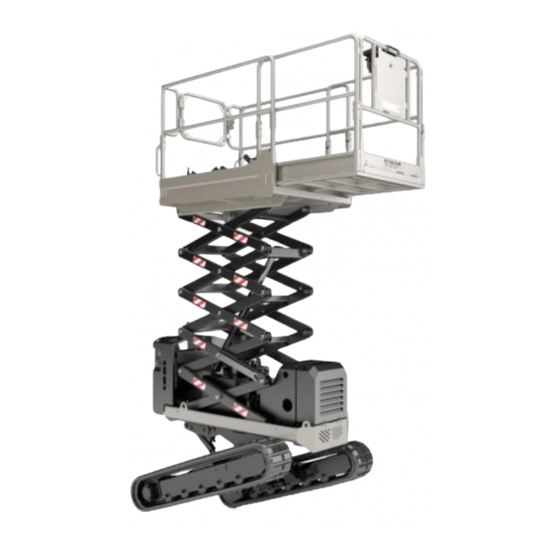
- Page 1 ATHENA 870-BL EVO Translation of original instructions Prior to commissioning the machine read carefully this Use and Maintenance Manual Note: table of contents at the end of the manual Edition Date 23/07/2020...
- Page 2 1.2 Details of Manual • Instruction manual for Elevating work platform • Version: ATHENA 870-BL EVO Note: Some of the photos and illustrations may not refer specifically to the version of the machine in your possession, but provide indications concerning the purpose for which they have been included.
- Page 3 ALMAC s.r.l. hereby declares that the information in this manual was congruent with the technical and safety specifications of the machine to which the manual refers.
- Page 4 ALMAC s.r.l. PAGE 1.5 MEWP identification data The machine named ATHENA 870-BL EVO is defined according to the technical standards in force (ref. UNI EN 280:2015), as: Mobile Elevating Work Platform (MEWP), belonging to group B, type 3 (point 1.4-EN 280) Meanings: GROUP B: All types of mobile elevating work platforms other than "Group-A"...
- Page 5 ALMAC s.r.l. PAGE 1.6 Performance Below are the configurations that the mobile elevating work platform can have during operation and transport. The work platform is provided of foldable guardrails not removable. Remove and install the guardrails is permitted only for special transport situations and...
- Page 6 ALMAC s.r.l. PAGE...
- Page 7 ALMAC s.r.l. PAGE Dimensions Length 2.11 m With basket closed Length 2.78 m With basket extended Maximum width 1.50 m Track width Maximum width 1.30 m Track narrow Minimum high 2.50 m Track width Minimum high 2.80 m Track narrow Basket large 1.2 m...
- Page 8 ALMAC s.r.l. PAGE Specification Capacity Nr operators onto the basket Lifting time Falling time Hydraulic pressure Hydraulic oil tank capacity Overcame sloop ° Max lateral sloop ° Max longitudinal sloop ° 20 / 16 Speed km/h Weight 2460 Max wind speed admitted 12.5...
- Page 9 ALMAC s.r.l. PAGE Engine data Z482-E3B Weight 53.1 kg Engine type VERTICAL, 4-CYCLE LIQUID COOLED Displacement 479 cm Power 9.9 kW @ 3600 rpm Torque 30 Nm @ 2500 rpm Oil (quantity) 2.5 Lt Diesel tank capacity 30 Lt Cooling...
- Page 10 ALMAC s.r.l. PAGE Maximum admitted transport high (Manual levelling and the adjustment of the travel speed admitted) MAXIMUM WORKING HEIGHT WITH MAXIMUM WORKING HEIGHT WITH TRAVELLING PERMITTED AND UNLIMITED TRAVELLING PERMITTED BUT LIMITED CARRIAGE WIDTH CARRIAGE WIDTH...
- Page 11 Work under guarantee must only be performed by workshops authorized by ALMAC S.r.l. and only when the Customer is up to date with the payments. The Customer will not be entitled to work under guarantee unless he consigns the equipment for repair within 30 days from the date of the first complaint, to be made in writing.
- Page 12 PAGE 1.8.1 Request for interventions during warranty period and formalities ALMAC S.r.l. must be notified of requests for spare parts or technical interventions under guarantee as soon as a defect is discovered. Always indicate the type of machine and its serial number when requesting spare parts under guarantee or technical interventions under guarantee.
- Page 13 ALMAC s.r.l. PAGE 1.10 Use of the manual Note: Keep this manual in an accessible place known to all users (operators and maintenance workers). Note: This manual must be kept in a protected place inside the compartment provided on the work platform so that it can be easily accessed for consultation throughout the entire technical life of the machine.
- Page 14 ALMAC s.r.l. PAGE 1.11 Intended use and improper uses 1.11.1 Intended use The machine described in this manual is a self-propelled elevating work platform designed to lift personnel and equipment to perform the following jobs: • professional gardening and general work •...
- Page 15 ALMAC s.r.l. PAGE Warning: The machine IS NOT SET FOR OPERATION IN ATEX CLASSIFIED ATMOSPHERES ALL LOADS must be positioned inside the work platform. NEVER LIFT LOADS HANGING FROM THE PLATFORM, from the lifting structure or from the railings. If the machine is used in places open to the public or in construction sites where persons may transit or remain in the vicinity, the WORK AREA MUST BE CORDONED OFF in a suitable way (e.g.
- Page 16 ALMAC s.r.l. PAGE 1.11.3 Cases that relieve the manufacturer from liability The manufacturer declines all liability in the following cases: • Use not indicated in this manual • Improper use of the machine or its use by untrained personnel • Use that fails to comply with the specific standards •...
- Page 17 ALMAC s.r.l. PAGE 2 SAFETY INFORMATION 2.1 Notification of commissioning and routine inspections The work equipment indicated in Annex VII to Legislative decree D.Lgs 81/2008 and successive amendments must be subjected to REGISTRATION and ROUTINE INSPECTIONS by the competent authorities, i.e. INAIL, the National Institute for...
- Page 18 *The law that currently governs health control and surveillance of workers is the Provision of the State-Regions Permanent Conference of 16 March 2006. Note: ALMAC S.r.l. declines all liability for damage to persons, animals and things deriving from: • failure to comply with the safety regulations •...
- Page 19 ALMAC s.r.l. PAGE 2.3 Warnings The following sign plates are affixed to the machine: • Identification • Instructions • Command/prohibition sign plates • Caution • Danger 2.3.1 Plates indicating instructions, obligations, dangers, prohibitions and warnings DO NOT TRANSLATE AT HEIGHT...
- Page 20 Note: The inclinations listed on the plate above refer to those LIMITS that cannot be exceeded with the machine. Almac s.r.l. has provided an electronic control system on the platform which limits the movements of the machine when the...
- Page 21 ALMAC s.r.l. PAGE...
- Page 22 ALMAC s.r.l. PAGE Note: The plates are affixed to the machine for the purpose of helping the operator and/or warning him of the risks to which he may be exposed when he uses the machine. In no way does the information on the plates substitute this Manual, which is the only reference document containing complete information.
- Page 23 ALMAC s.r.l. PAGE 2.3.2 Meanings of the sign pictograms Warning / Danger. This symbol means that you must take care or that danger is present. Failure to comply with this alert indication could cause damage to the machine, the operator or exposed persons.
- Page 24 ALMAC s.r.l. PAGE 2.4 Provisions and prohibitions • Read this manual carefully before starting, using, servicing or performing other operations on the machine. • The MEWP must always be kept in perfect conditions by following the maintenance program described in the Maintenance Chapter.
- Page 25 ALMAC s.r.l. PAGE 2.5 Transport and loading You are advised to check the dimensional limits established for means of transport if the machine must be transported to its specific work site. The machine can be loaded onto the vehicle in two different ways:...
- Page 26 ALMAC s.r.l. PAGE 2) Lifting the platform using a CE certified beam (not included) and using hooks and steel ropes hooked to the holes marked with signs (see photo below). Warning: the maximum weight of ATHENA BL in the heaviest configuration is...
- Page 27 ALMAC s.r.l. PAGE Note: Once the machine has been loaded onto the vehicle, it must be fastened in place using belts; connect them to the special red eye-bolts. Note: Make sure that the platform is FULLY LOWERED before transporting the machine.
- Page 28 ALMAC s.r.l. PAGE 2.6 Checks on the machine before each use • Visually check under and around the machine to make sure that there are no oil or fuel leaks. If leaks are discovered, follow the MAINTENANCE instructions. • Make sure that there is no hydraulic oil leaking from the hoses and from the other components (cylinders, distributors, fittings, etc.).
- Page 29 ALMAC s.r.l. PAGE 2.7 General safety indications on the use of the platform The instructions given below must be followed. • It is forbidden to use ladders or other structures in the basket to increase the height of the machine.
- Page 30 ALMAC s.r.l. PAGE 2.8 Safety indications on the use of the travel function The instructions given below must be followed. • Make sure movements are done on flat, sturdy ground. To do this, use the spirit level located on the work platform.
- Page 31 ALMAC s.r.l. PAGE the tracks. ALWAYS PROCEED WITH THE TRACK SHOES RESTING ON THE SAME HORIZONTAL PLANE. • Driving over an obstacle creates a gap between the bearing rollers and track, which could consequently slip out of its housing. • If you change direction in a situation where the track could move sideways owing to an obstruction, the track could slip out of its housing.
- Page 32 ALMAC s.r.l. PAGE • Avoid smooth, slippery and/or icy surfaces and those covered with sand: they could cause a risk of sliding or tipping during levelling. NO ICE! NO SAND! NO DUST OR SMOOTH SURFACES! Warning: during movement with ELECTRICAL POWER, be careful of the...
- Page 33 ALMAC s.r.l. PAGE 2.9 Mandatory safety indications to follow before lifting the work platform above the transport height The instructions given below must be followed. After having levelled it, lift the work platform only after making sure, both visually and by moving inside the work platform, that all 4 ends of the tracks rest on the ground.
- Page 34 ALMAC s.r.l. PAGE 2.10 Safety checks on the operation of the platform, to be performed before use The instructions given below must be followed. • With the platform in the transport configuration, place the machine with the frame tilted with respect to the horizontal by a value greater than 0.5° on the lateral.
- Page 35 ALMAC s.r.l. PAGE • Check that with the platform lifted higher than the transport height but lower than the maximum travel height (light 2 on) and moving on non-level terrain, the machine stops automatically when the inclination of the frame with respect to the horizontal exceeds 1°.
- Page 36 Only perform the MAINTENANCE and ADJUSTMENT operations described in this Manual. Contact the ALMAC S.r.l. assistance service only, if other operations are required (e.g. if faults occur). All MAINTENANCE work must be performed in compliance with the laws in force governing safety and protection of the environment.
- Page 37 ALMAC s.r.l. PAGE Ground Controls The photo above shows how the locking system of the extensible structure must be positioned during maintenance work. By means of the "ground controls", it is possible to lift the work platform until it is possible to place the two locking brackets vertically and aligned with the pins below.
- Page 38 ALMAC s.r.l. PAGE • Do not use open flames for lighting purposes when performing maintenance. • Make sure there are no fluids under pressure before disassembling unions or pipes: oil spattering out under pressure can cause serious injuries. Immediately call a physician if injuries occur or the fluid from pipes is accidentally ingested.
- Page 39 ALMAC s.r.l. PAGE 3 DESCRIPTION OF THE MACHINE 3.1 Structure of the equipment This section describes the main components of the machine and their functions. 3.1.1 Work platform assembly 3.1.2 Scissor assembly 3.1.2 Tank and chassis assembly...
- Page 40 ALMAC s.r.l. PAGE 3.1.1 Work platform assembly 1. Control push-button panel 2. Control console emergency button (console) 3. Glove box 4. Extensible work platform 5. Spirit level 7. Device for the extension of the work 6. Socket on work platform platform 8.
- Page 41 ALMAC s.r.l. PAGE 3.1.2 Scissor assembly 9. Lifting cylinder 10. Lifting cylinder shut-off valve 11. Pressure transducer for load control 12. Scissor angle sensor...
- Page 42 ALMAC s.r.l. PAGE 3.1.3 Tank assembly 13. Ladder to access the platform 14. Main hydraulic unit 15. Main differential panel 16. Ground control panel 17. Flashing light 18. Ground control panel emergency button...
- Page 43 ALMAC s.r.l. PAGE 19. ECU electronic control unit 20. Battery disconnect switch 21. Emergency descent device 22. Hydraulic oil tank 23. Discharge filter 24. Intake filters (in the tank)
- Page 44 ALMAC s.r.l. PAGE 25. Oil tank refill cap 26. Visual hydraulic oil level 27. Combustion engine starter battery 28. Booster for management of third travel speed 29. Electrical engine 30. Inverter differential panel (if present)
- Page 45 ALMAC s.r.l. PAGE 31. Frame angle sensor 32. "Proactive levelling" angle sensor Proactive levelling safety valves Proactive levelling limit “ ” “ ” switch 35. Combustion engine 36. Fuel tank...
- Page 46 ALMAC s.r.l. PAGE 37. Bi-levelling chassis...
- Page 47 ALMAC s.r.l. PAGE 3.2 Control stations 3.2.1 Mobile control push-button panel (console) The platform is equipped with a mobile control push-button panel (console) which allows for normal operation on the work platform. The console can be located in the dedicated metal support attached to the railing of the platform or removed and held by the operator.
- Page 48 ALMAC s.r.l. PAGE Warning: If the platform is transported on vehicles, always secure the support by means of the threaded knob. The push-button panel can also be disconnected from the spiral cable by unscrewing the ferrule indicated with A. Warning: Do not touch ferrule B; if ferrule B is turned, the wires inside the connector will be damaged.
- Page 49 ALMAC s.r.l. PAGE Warning: For all operations that required lifting the work platform above the transport height, the console and the operator must be inside the platform itself.
- Page 50 ALMAC s.r.l. PAGE Identification Function and Status Description of the function PLANARITY ALARM (with indicator light 3 on) Lateral inclination 0°<0.5° Longitudinal inclination 0° <0.5° FLASHING Lateral inclination >0.5° <3° (If the platform does not exceed the maximum Longitudinal inclination >0.5° <3°...
- Page 51 ALMAC s.r.l. PAGE Identification Function and Status Description of the function Load work platform between 0 and 260Kg (1.2 nominal load) Load work platform greater than or equal to 260Kg (1.2 nominal load); the normal operation of the platform is prevented...
- Page 52 ALMAC s.r.l. PAGE Identification Function and Status Description of the function DRIVING MODE SELECTOR CENTRAL position Standard operation traction FORWARD/REVERSE enabled using 2 joysticks DC-S position Simultaneous movement Selector switch FORWARD/REVERSE of the tracks with the RH joystick only (11)
- Page 53 ALMAC s.r.l. PAGE 3.2.2 Ground control using the mobile push-button panel With the mobile control push-button panel, as well as allowing for the normal operation of the work platform, it is possible to temporarily remove and use the machine from the ground.
- Page 54 ALMAC s.r.l. PAGE 3.2.3 Ground controls The platform features a control console located on the chassis at the back of the machine. These controls are useful for the operator on the ground for platform maintenance or for emergency situations (red mushroom button).
- Page 55 ALMAC s.r.l. PAGE Identification Function and Status Description of the function Display of the hours of operation and machine status, with Display an indication of any alarms. PLATFORM UP / DOWN SELECTOR To control the upward movement of work platform,...
- Page 56 ALMAC s.r.l. PAGE 3.3 Storage compartment On the platform, under the control console, there is a compartment, which can be opened by hand. It contains: • This Use and Maintenance Manual • The spare parts catalogue • Wiring diagrams • Hydraulic diagrams •...
- Page 57 ALMAC s.r.l. PAGE 3.4 Platform operation safety devices Warning: Periodically verify that the safety devices are operating correctly. During work, the operator must be able to assess, recognize and avoid all dangers and must immediately inform the persons in charge of any faults in the...
- Page 58 ALMAC s.r.l. PAGE This sensor is connected in parallel to the limit switch that controls that the platform is at a height lower than the transport height (the 12V output signal is interrupted if the platform is lifted above the transport height).
- Page 59 ALMAC s.r.l. PAGE The limit switch and the relays are monitored by the control unit, which generates an alarm if a fault is detected. If the limit switch malfunctions, the Proactive levelling function is disabled. If the relays malfunction (bonding), the entire operation of the machine, except for the downward movement, is disabled.
- Page 60 ALMAC s.r.l. PAGE 3.4.4 Load limiting device The machine is equipped with a work platform that, once extended, has a surface area greater than 1 m². For this reason, on the cylinder there are two pressure transducers which, with the angle sensors of the frame and of the scissors, make up a system able to detect whether the load on the work platform exceeds the nominal load by 20%.
- Page 61 (1-2) in order to limit the pressures relating to the operation of the machine, preserving the integrity of the various components. These valves need no adjustments since they are calibrated by ALMAC S.r.l. when the machine is tested. The diagram below illustrates the integrated power pack and the position of the pressure relief valves described above.
- Page 62 ALMAC s.r.l. PAGE Warning: modifications to the positions of the maximum pressure valves without authorization from ALMAC S.r.l. will void the warranty and any claims made by the customer. 3.5.2 Hydraulic block safety devices The hydraulic block features three solenoid valves with possible manual by-pass.
- Page 63 ALMAC s.r.l. PAGE 3.5.3 Hydraulic failure safety devices The hydraulic system of the lifting circuit, in the event that there is an accidental fault in the hydraulic piping that feeds the lifting cylinder of the work platform, features a one-way valve, normally closed (1), electrically DRIVEN and connected directly to the cylinder, which prevents the uncontrolled descent of the work platform from any height, thus avoiding dangerous situations.
- Page 64 ALMAC s.r.l. PAGE Proceed as described below to restore the machine to normal operating conditions: 1. Repair the damaged hydraulic hose and/or connections 2. Fill and bleed the hydraulic circuit 3. Lift the platform to its maximum height If the hydraulic hoses that supply the track chassis levelling cylinders malfunction and suddenly change the track and the inclination, dedicated BALANCING VALVES prevent the track from moving suddenly (ref.Section 5.10.2...
- Page 65 ALMAC s.r.l. PAGE If one of the balancing valves malfunctions (fault not provided for in UNI EN 280:2015), there are 4 normally closed valves placed on each of the dangerous movements of the cylinders of the chassis. These valves are fed (kept open) only if the chassis is inclined in the two axes by an angle lower than 3°, or if the...
- Page 66 ALMAC s.r.l. PAGE 3.6 Blackout safety devices 3.6.1 230V external power source On the work platform there is a power socket to supply the power tools required during work. For safety reasons, a device is installed so as to cut-out the electricity supply in case of over-voltage and "differential circuit breaker"...
- Page 67 ALMAC s.r.l. PAGE 3.6.2 220V inverter (optional) If the machine is equipped with a 220V inverter to power the outlet on the work platform, the following safety devices will also be present: 1) Insulation control device between the cables that go from the inverter to...
- Page 68 ALMAC s.r.l. PAGE 3.6.3 12V system Near the access ladder is the "battery isolator" (3) which physically disconnects the 12v electric line coming from the battery supplying the various users. It is recommended to operate this device at the end of the work day, to prevent draining the batteries.
- Page 69 ALMAC s.r.l. PAGE 3.7 Platform operation devices which are not part of the safety system On both connecting rod assemblies (right and left) connecting the tracked chassis and the central frame, there are two Can Bus angle sensors. The angle sensors are redundant (thus consisting of two separate sensors) and monitor the X inclination axis of the respective connecting rod.
- Page 70 ALMAC s.r.l. PAGE 3.8 Foot pedal The pedal in the basket is used as a safety system that is: Free pedal: the machine can only move with the basket completely lowered (transportation position), all other movements are inhibited; Pedal pressed: all movements are enabled.
- Page 71 ALMAC s.r.l. PAGE 4 Instructions for use 4.1 Preliminary operations 4.1.1 Suitability of the soil To assess whether the ground is fit to bear the machine, it is extremely important to ensure that the ground surface does not allow the machine to slip once it has been stopped for work.
- Page 72 ALMAC s.r.l. PAGE DO NOT TRANSLATE AT HEIGHT ON WEAK, MUDDY, FROZEN, SLIPPERY GROUNDS OR CLOSE TO HOLES, MOATS, DRAINS OR DANGER CRACKS THAT OPEN UP TO EMPTY SPACES. Note: Do not use the MEWP if you are doubtful about the fitness of the ground surface.
- Page 73 ALMAC s.r.l. PAGE 4.1.2 Action of the wind It is forbidden to use the machine if the wind speed exceeds 12.5 m/s. The following chart describes the consequences of different wind speeds (Beaufort scale). Scale of the Italian Hydrographic Service...
- Page 74 ALMAC s.r.l. PAGE Danger: The platform must never be used when wind speed corresponds to a value greater than 6 of the Beaufort scale. Work must be performed with the utmost warning with wind speeds between 4 and 6 of the scale.
- Page 75 ALMAC s.r.l. PAGE Warning: IT IS FORBIDDEN to block the gate in such a way as to keep access to the platform open.
- Page 76 ALMAC s.r.l. PAGE 4.1.3.1 Easy-Access system to facilitate access to the work platform A system that allows the operator to place the machine in such a way that it is easier to climb up the ladder to access the work platform.
- Page 77 ALMAC s.r.l. PAGE 4.1.4 Work platform extension The work platform is provided with a driven mechanism that enables to further extend the work area so as to reach more distant parts. To extend the work platform, it is necessary to: 1.
- Page 78 ALMAC s.r.l. PAGE Warning: while descending from the working position, pay warning to possible obstacles beneath the work platform to prevent the platform from overturning or being damaged!
- Page 79 ALMAC s.r.l. PAGE 4.1.5 Checking the fuel level Before turning on the engine and/or starting a work shift, it is advisable to check the fuel level. The fuel level is visible in the ground control area (1). There is also a reserve sensor (2). If the fuel level is too low, the machine will emit an acoustic signal, the FUEL alarm will appear on the display and after 15 seconds the engine will turn off to avoid emptying the fuel system completely.
- Page 80 ALMAC s.r.l. PAGE 4.1.6 Checking the oil level in the engine Check the engine oil level before starting it, or when more than 5 minutes have gone by after stopping it. Pull out the oil level indicator, clean it by wiping it and reinsert it.
- Page 81 ALMAC s.r.l. PAGE • Unlock the fastenings of the expandable basket RH railing • Fold the railing according to the figure • Exit the platform before folding the outer rails • Unlock the fastenings of the LH railing of the expandable work platform •...
- Page 82 ALMAC s.r.l. PAGE • Should it be required to transport the machine, it is necessary close expandable part up to the "T" lock. Unlocking the railing fastenings To unlock the railing fastenings, it is necessary to: 1) Turn the safety catch (A) of the locking pin (B) and then pull it from its seat...
- Page 83 ALMAC s.r.l. PAGE Before stepping on the platform, it is absolutely mandatory to put all the railings back in the vertical position and secure them as shown in the figure.
- Page 84 ALMAC s.r.l. PAGE 4.2 Machine operation 4.2.1 Starting the internal combustion engine To start the internal combustion engine and the hydraulic pumps, use the ignition key on the ground controls. The key-switch functions are: • (CENTRAL): Machine off - electrical system not powered •...
- Page 85 ALMAC s.r.l. PAGE 4.2.2 Starting the current source During operation with the INTERNAL COMBUSTION ENGINE, it is possible to turn the selector (6) to the OUT 220V position. In this way, it will be possible to use the 220V power in the outlet on the work platform (only for machines with inverter).
- Page 86 ALMAC s.r.l. PAGE Warning: the connection to a network that does not meet the requirements of the electrical engine may cause serious damage to some of the components of the machine. The machine features electrical components (contactors and differential circuit breakers) that disconnect the power to the engine and to the system.
- Page 87 ALMAC s.r.l. PAGE The platform is fitted with a tracked chassis with dual speed gear motors equipped with a negative brake, therefore the machine will remain blocked whenever the forward or backward movement is interrupted To turn the platform, move the levers as indicated in the following illustrations.
- Page 88 ALMAC s.r.l. PAGE Travel is enabled or disabled depending on the status of the travel approval light located on the control panel. It provides the following information: • On: travel allowed up to a maximum height of 4.5 m platform floor, proactive levelling active •...
- Page 89 ALMAC s.r.l. PAGE It is forbidden to travel above the transport height in the following conditions: • Wet ground • Snowy and/or icy ground • Dry asphalt but covered with sand, gravel or other aggregates Warning: slipping hazard! 4.2.4.1 Standard travel mode...
- Page 90 ALMAC s.r.l. PAGE 4.2.4.2 Easy-Drive System (ED-S) Moving the selector 8 on the push-button panel to the "ED-S" position activates a special function that allows you to control the rotation of the platform, especially when operating on cultivated or grassy terrain, so that the tracks do not rip the cultivation during the manoeuvre.
- Page 91 ALMAC s.r.l. PAGE Adjusting the speed: This is possible using selector 9 on the console that controls the internal combustion engine accelerator. 4.2.4.4 Turtle In this particular travel mode, the internal combustion engine operates at accelerated rate. This allows to have the correct power for the platform to climb up slopes and for the machine to be loaded onto vehicles.
- Page 92 ALMAC s.r.l. PAGE 4.2.4.6 Travel mode with the work platform above the transport height With the platform raised above the transport height, the maximum travel speed is automatically limited to a maximum value of 0.4Km/h. All the functions remain the same as with the platform in the transport configuration.
- Page 93 ALMAC s.r.l. PAGE 4.2.5.1 Levelling in the transport configuration (with the upward movement of the work platform) With the work platform completely lowered, it is possible to activate the automatic levelling by keeping selected the work platform upward control. The system will bring the frame back to an inclination of less than 0.5°...
- Page 94 ALMAC s.r.l. PAGE 4.2.5.2 Levelling in the transport configuration (operating the manual controls) The MANUAL lateral and longitudinal levelling of the platform is possible only within the TRANSPORT HEIGHT (platform floor <2mt). It must be performed by carefully checking the inclination on the spirit level situated on the work...
- Page 95 ALMAC s.r.l. PAGE If the inclination of the platform remains within ± 0.5° both laterally and longitudinally, it is possible to lift the work platform. Warning: manual levelling is less accurate than automatic levelling 4.2.5.3 Dynamic Levelling during travel Note: dynamic levelling can be activated only with the platform completely lowered.
- Page 96 ALMAC s.r.l. PAGE because it would be enough to have the normal frame inclination control made in performance level D as required in section 5.3.2.3 of the same standard. This additional safety system is described in paragraph 3.4.2 "Redundant frame inclination and height control device"...
- Page 97 ALMAC s.r.l. PAGE • It is necessary to release the joysticks • When the joysticks are reactivated, the platform will be levelled again. The levelling can be performed also by commanding the upward movement of the work platform. Warning: If the levelling is performed by means of the joysticks, once the...
- Page 98 ALMAC s.r.l. PAGE The table below lists the maximum permitted configurations previously described. Configuration summary table Height of work Frame Travel Levelling Platform up platform inclination Allowed Allowed at Lower that the Manual Allowed after transport height Dynamic levelling levelling...
- Page 99 ALMAC s.r.l. PAGE 4.2.6 Lifting/descent of the work platform The work platform can be lifted by means of the dedicated selector on the control push-button panel. The lifting and descent speed are controlled by the electronic control unit (ECU). The platform descent can also be performed with the combustion engine off but the electrical panel ON.
- Page 100 ALMAC s.r.l. PAGE 4.3 Messages and alarms on the hour counter The hour counter, placed next to the ladder, allows to display the machine status. This display also shows any errors and/or alarms that may occur. If there are no alarms present, the display will show the hours of work with the...
- Page 101 ALMAC s.r.l. PAGE If there are no alarms at the moment but there were alarms previously (alarms caused by malfunctions that appear intermittently), the service symbol will appear on the display: The control unit can store up to 16 alarms which are shown by pressing the right button of the hour counter.
- Page 102 ALMAC s.r.l. PAGE CODE DESCRIPTION FUEL fuel level (only Kubota engine) (Warning: This alarm is not stored) Starter battery voltage lower than 9V Starter battery voltage higher than 16V EPROM memory internal error CAN network communication error Frame angle sensor redundancy error...
- Page 103 ALMAC s.r.l. PAGE 4.4 Stopping the machine 4.4.1 Normal stop During normal platform use, releasing the TRANSLATION joysticks (10 and 11) stops the movement. Each track installed has a braking system that prevents the machine from moving unless hydraulic pressure is exercised to disengage it.
- Page 104 ALMAC s.r.l. PAGE 4.4.2 Emergency stop In abnormal circumstances, or situations in which all machine movements must be stopped, the operator can IMMEDIATELY STOP all the machine functions by pressing the MUSHROOM-SHAPED button on the push-button, or the emergency button place on the GROUND CONTROLS (see figures below).
- Page 105 ALMAC s.r.l. PAGE 5 Emergency procedures 5.1 Emergency manual descent Following a failure in the electrical system or hydraulic circuit, the platform DESCENT manoeuvre can be performed from any height by means of the emergency control at ground level. In this case, the operator on the ground (remember that at least one operator must be present at ground level to ensure the platform is used in safe conditions) must pull the hydraulic valve control installed on the lifting cylinder.
- Page 106 5.3 Emergency movements from hydraulic block Warning: this operation must be performed only by qualified technicians trained by Almac Srl If the control unit is not working but it is possible to turn on the internal combustion engine or the electrical engine, then it will be possible to perform then movements of the machine directly from the hydraulic block.
- Page 107 ALMAC s.r.l. PAGE 5.4 Use hand pump in case of emergency The Hand Pump is installed on the machine for the use in emergency situation only. The purpose of the Hand Pump is to raise the platform should access inside the scissor stack be required if the engine or operating systems are not operational.
- Page 108 ALMAC s.r.l. PAGE 2- Remove the left crankcase from the access ladder; 3- Screw completely the slider of the BP2 valve; 4- Insert the rod into the hand pump housing;...
- Page 109 ALMAC s.r.l. PAGE 5- Simultaneously press the sliders of the valves SV1, SP2 and at the same time move the pump lever horizontally until the desired basket height is reached. 6- At conclusion of emergency operations, the operator must release the screw on valve BP2.
- Page 110 ALMAC s.r.l. PAGE ORDINARY MAINTENANCE SCHEDULE TABLE 50 100 250 500 Visual and functional checks as specified Discharge filter cartridge replacement Suction filters replacement Check and, if necessary, grease the runners and nylon wheels Check the hydraulic oil level Change the hydraulic oil...
- Page 111 Warning: Do not use the machine if one of its mechanical or hydraulic elements or a control or safety device is faulty! Immediately notify an Almac Srl customer assistance centre 6.1.2 Checks before each use Prior to commissioning and before each use the machine must undergo the visual and functional checks given below.
- Page 112 ALMAC s.r.l. PAGE • • Visually check under and around the With platform transport machine to make sure that there are no configuration, place the machine with the oil or fuel leaks. frame tilted with respect to the horizontal by a •...
- Page 113 ALMAC s.r.l. PAGE difficulties or even death. non-level terrain, machine stops automatically when the inclination of the frame with respect to the horizontal exceeds 1°. Release the travel control; when this control is operated again or when the lifting control is operated, the system must bring the...
- Page 114 ALMAC s.r.l. PAGE 6.2.1 Checking and tightening screws, bolts, plug ring nuts The operation of the following components must be checked. If necessary, the parts must be tightened with the appropriate tools as indicated in the charts on the following pages.
- Page 115 ALMAC s.r.l. PAGE • Condition of ladder • Condition of lifting structure (scissors) • Condition of the frame • Status of the bi-levelling structure and of the tracked chassis • In particular check if there is any rust in the structure •...
- Page 116 ALMAC s.r.l. PAGE The surfaces to be greased are those in contact with the runners, both in the frame and under the work platform (see figures below): Remove all dirt from the parts before greasing. Use grease type PAKELO BEARING EP 2 or equivalent.
- Page 117 ALMAC s.r.l. PAGE Remove all dirt from the parts before greasing. Use the same grease specified for the runners. 6.2.6 Checking the hydraulic tank oil level and topping up if necessary The hydraulic oil level is checked by means of a level indicator located directly on the tank.
- Page 118 ALMAC s.r.l. PAGE In this configuration, the oil level must be as shown in the figure below.
- Page 119 ALMAC s.r.l. PAGE A = 60mm...
- Page 120 ALMAC s.r.l. PAGE 6.2.7 Hydraulic reservoir oil change The hydraulic oil in the tank must be changed with the frequency indicated in the general chart. 1. Collect the used oil in a suitable vessel and dispose of it in the proper way.
- Page 121 ALMAC s.r.l. PAGE 6.2.8 Checking the operation of the maximum pressure valves With the frequency indicated in the general chart, check the operation of the maximum pressure valves of the distributor. To test them, connect two pressure gauges with a full scale of 250 bar to the pressure outlets supplied (4 and 5).
- Page 122 Only specialised technicians, authorised by Almac Srl, must perform this operation. The valves are calibrated during the testing phase performed by ALMAC Srl and should not require further adjustment unless: • the hydraulic circuit is replaced •...
- Page 123 • Always keep the battery clean, dry and free from oxidation. • If the battery is replaced, always comply with the instructions supplied with it. 6.2.9.2 Maintenance The batteries chosen by ALMAC S.r.l. and installed on all models are of the maintenance-free type. These batteries feature construction technology that “...
- Page 124 ALMAC s.r.l. PAGE 6.2.9.3.1 Charging method No. 1 with 12V battery charger Recharge the battery only in ventilated areas. With the main switch QS1 (battery disconnect switch) turned to the ON position, connect the positive pole of the battery charger to the 150A fuse or to the dedicated connector placed under the ladder;...
- Page 125 ALMAC s.r.l. PAGE 6.2.9.3.2 Charging method No. 2 using the 230V plug in the ladder If the machine is equipped with a 230V electric motor, it is possible to recharge the battery simply by connecting the plug in the ladder to the external power source.
- Page 126 ALMAC s.r.l. PAGE 6.2.10 Hydraulic filter replacement Replace the discharge filters of the hydraulic circuit at the frequencies indicated in the general chart. The hydraulic oil tank features: 2 or 4 suction filters inside the tank (1) 1 discharge filter in the top part of the tank (2).
- Page 127 ALMAC s.r.l. PAGE To replace the discharge filters located inside the hydraulic tank, proceed as follows: 1) Arrange the machine with the extending structure lifted and block it with the special mechanical locks for maintenance. Now turn it off and...
- Page 128 ONLY USE GENUINE SPARE PARTS when replacing the filters. Contact the ALMAC technical assistance service. Do not reuse used oil. Do not dispose of it in the environment. Used oil must...
- Page 129 If the operations described above take place in the indicated sequence, it means that the angle sensor is working properly. Warning: if the conditions indicated above are not met, do not use the machine and contact a qualified technician trained by Almac Srl...
- Page 130 If the operations described above take place in the indicated sequence, it means that the angle sensor is working properly. Warning: if the conditions indicated above are not met, do not use the machine and contact a qualified technician trained by Almac Srl...
- Page 131 3° on the longitudinal • Try to perform the manual levelling operations; make sure that they are all disabled. Warning: if the movements are not disabled, do not use the machine and contact a qualified technician trained by Almac Srl...
- Page 132 ALMAC s.r.l. PAGE 6.2.14 Checking the differential circuit breaker With the frequency indicated in the general chart, check the differential circuit breaker Connect the plug in the ladder to an electric power supply that conforms to the following specifications: • Voltage: 230 v ± 10% •...
- Page 133 ALMAC s.r.l. PAGE 6.2.15 Electrical insulation monitoring device operation test With the frequency indicated in the general chart, check the operation of the device that monitors the electrical insulation of the 220V power supply of the inverter (only if present).
- Page 134 ALMAC s.r.l. PAGE 6.2.16 Manual emergency device operation test Test the operation of the manual EMERGENCY DESCENT device at the inspection frequency indicated in the general chart. Near the access ladder, indicated with special stickers, there is a control lever which, when pulled, allows the platform to lower in any condition, i.e.:...
- Page 135 Warning: At the end of the test, restore the connectors as before. Warning: if the conditions indicated above are not met, do not use the machine and contact a qualified technician trained by Almac Srl...
- Page 136 Checking the seal of the cylinder balancing valves Warning: this operation must be performed only by qualified technicians trained by Almac Srl With the frequency indicated in the general chart (as for the Proactive levelling safety valves), check the seal of the flanged valves on the cylinders.
- Page 137 (because of a malfunction or impurities trapped in the cursor). Warning: if the test has a negative outcome, do not use the machine and contact a qualified technician trained by Almac Srl...
- Page 138 ALMAC s.r.l. PAGE 6.2.19 Procedure with remote controller for checking the seal of the cylinder balancing valves Warning: this operation must be performed only by qualified technicians trained by Almac Srl...
- Page 139 ALMAC s.r.l. PAGE Push the emergency push button on controller; Select commands on chassis (22); Release the emergency push button on Console; The lamps 1‐2‐3‐4 come on, when only the red lamps 1‐4 are steady press two times selector 14 forward and after two times selector 12 forward...
- Page 140 ALMAC s.r.l. PAGE 6.2.20 Maintenance of the engine Below are general instructions for the correct maintenance of the engine. In any case, always consult the use and maintenance manual of the engine.
- Page 141 ALMAC s.r.l. PAGE...
- Page 142 ALMAC s.r.l. PAGE...
- Page 143 ALMAC s.r.l. PAGE...
- Page 144 ALMAC s.r.l. PAGE...
- Page 145 ALMAC s.r.l. PAGE...
- Page 146 ALMAC s.r.l. PAGE...
- Page 147 ALMAC s.r.l. PAGE...
- Page 148 ALMAC s.r.l. PAGE...
- Page 149 ALMAC s.r.l. PAGE...
- Page 150 ALMAC s.r.l. PAGE 6.2.21 Track inspection and tensioning Check track tension at the inspection frequency indicated in the general chart. Pull the track slightly upwards in correspondence with the centre line; the deformation must be of approximately 2 cm. If the track sags and becomes too noisy as it moves, it must be tightened as...
- Page 151 ALMAC s.r.l. PAGE 6.2.22 Checking the tracks for wear Check the wear and condition of the tracks, replacing them when the tread is equal to or less than 10 mm. The tracks must be changed even before they reach this limit if they are cuts or tears are noted.
- Page 152 ALMAC s.r.l. PAGE 6.2.23 Replacing the tracks WARNING: it is forbidden to open the reducer for any operation not provided for by scheduled maintenance. The manufacturer shall not be held responsible for any operations not included in scheduled maintenance that have caused damage to property and/or harmed people.
- Page 153 ALMAC s.r.l. PAGE 6- Using the nut supplied (point A) 7- Move the front wheel back by pressing on the track with your foot...
- Page 154 ALMAC s.r.l. PAGE WARNING: BE CAREFUL WHEN THE TRACK FALLS TO THE GROUND 8- Lift the track at the lower centre line 9- Pull the track out , prying between the track itself and the idler wheel 10- To install the new track, proceed as indicated in the previous points, but...
- Page 155 ALMAC s.r.l. PAGE 6.2.24 Track reduction gear oil level inspection Check the level of the oil in the track reduction gears at the frequencies given in the general chart. Comply with the procedure described below. HOW TO CHECK AND TOP UP THE REDUCTION GEAR OIL Before proceeding, check the drawings below to find out which type of reduction gear unit is installed in your undercarriage.
- Page 156 ALMAC s.r.l. PAGE...
- Page 157 In addition, the raw materials used to make it must be recovered for recycling purposes where possible. Note: ALMAC S.r.l. declines all liability for damage to persons, animals or things deriving from reuse of parts of the equipment for functions or assembly situations differing from the original ones.
- Page 158 ALMAC s.r.l. PAGE • Separate non-polluting materials from polluting ones when disposing of the machine (insulating materials, plastic, rubber, etc.) • Never burn the machine or parts of it because the combustion products of plastic materials and paints could develop harmful, polluting gases.
- Page 159 ALMAC s.r.l. PAGE 8 ATTACHMENTS 8.1 Declaration of conformity...
- Page 160 ALMAC s.r.l. PAGE 8.2 Report register Report register The Report register is issued to the platform user with reference to: ➢ technical standard UNI EN280:2015 ➢ Legislative Decree D.Lgs 17/2010 Implementation of Machinery – Directive 2006/42/EC The purpose of this Register is to record events concerning the life of the machine;...
- Page 161 ALMAC s.r.l. PAGE MANDATORY ROUTINE INSPECTIONS Date Observations Seal/Signature...
- Page 162 ALMAC s.r.l. PAGE Type of inspection Description Checking and tightening screws, bolts, plug ring nuts Date Observations Signature 1st year 2nd year 3rd year 4th year 5th year 6th year 7th year 8th year 9th year 10th year NOTE: frequency of the operation as indicated in the table in Chapter 6. Daily registration is not necessary, but should be made at least once a year when other operations are performed.
- Page 163 ALMAC s.r.l. PAGE Type of inspection Description Damage to tubes and cables Date Observations Signature 1st year 2nd year 3rd year 4th year 5th year 6th year 7th year 8th year 9th year 10th year NOTE: frequency of the operation as indicated in the table in Chapter 6. Monthly registration is not necessary, but should be made at least once a year when other operations are performed.
- Page 164 ALMAC s.r.l. PAGE Type of inspection Description Hydraulic tank oil level inspection Date Observations Signature 1st year 2nd year 3rd year 4th year 5th year 6th year 7th year 8th year 9th year 10th year NOTE: frequency of the operation as indicated in the table in Chapter 6. Daily registration is not necessary, but should be made at least once a year when other operations are performed.
- Page 165 ALMAC s.r.l. PAGE Type of inspection Description Check operation maximum pressure valve Date Observations Signature 1st year 2nd year 3rd year 4th year 5th year 6th year 7th year 8th year 9th year 10th year NOTE: frequency of the operation as indicated in the table in Chapter 6.
- Page 166 ALMAC s.r.l. PAGE Type of inspection Description Check the operation of the angle sensors Date Observations Signature 1st year 2nd year 3rd year 4th year 5th year 6th year 7th year 8th year 9th year 10th year NOTE: frequency of the operation as indicated in the table in Chapter 6.
- Page 167 ALMAC s.r.l. PAGE Type of inspection Description Check the operation of the differential switch of the 230V outlet Date Observations Signature 1st year 2nd year 3rd year 4th year 5th year 6th year 7th year 8th year 9th year 10th year NOTE: frequency of the operation as indicated in the table in Chapter 6.
- Page 168 ALMAC s.r.l. PAGE Type of inspection Description Manual emergency device operation test Date Observations Signature 1st year 2nd year 3rd year 4th year 5th year 6th year 7th year 8th year 9th year 10th year NOTE: frequency of the operation as indicated in the table in Chapter 6.
- Page 169 ALMAC s.r.l. PAGE Type of inspection Description Engine oil change Date Observations Signature 1st year 2nd year 3rd year 4th year 5th year 6th year 7th year 8th year 9th year 10th year NOTE: frequency of the operation as indicated in the table in Chapter 6.
- Page 170 ALMAC s.r.l. PAGE Type of inspection Description Track inspection and replacement Date Observations Signature 1st year 2nd year 3rd year 4th year 5th year 6th year 7th year 8th year 9th year 10th year NOTE: frequency of the operation as indicated in the table in Chapter 6.
- Page 171 ALMAC s.r.l. PAGE Type of inspection Description Make sure that parking brake functions Parking brake correctly when machine stops Date Observations Signature 1st year 2nd year 3rd year 4th year 5th year 6th year 7th year 8th year 9th year 10th year NOTE: frequency of the operation as indicated in the table in Chapter 6.
- Page 172 ALMAC s.r.l. PAGE Type of inspection Description Make sure that parking brake functions Check the levelling cylinder balancing valves correctly when machine stops Date Observations Signature 1st year 2nd year 3rd year 4th year 5th year 6th year 7th year...
- Page 173 ALMAC s.r.l. PAGE Serious faults Date Description of fault Solution Spare parts used Description Code Serious faults Date Description of fault Solution Spare parts used Description Code Serious faults Date Description of fault Solution Spare parts used Description Code...
- Page 174 Seller's business name: Seller Purchaser Copy to send to ALMAC SRL ownership of the MEWP: serial no. year of manufacture was transferred to:...
- Page 175 ALMAC s.r.l. PAGE 8.4 Hydraulic diagram See attachment 8.5 Wiring diagram See attachment...
- Page 176 ALMAC s.r.l. PAGE 9 INDEX GENERAL INFORMATION __________________________________________________________ 2 OCUMENTS SUPPLIED WITH EACH MACHINE ____________________________________________ 2 ETAILS OF ANUAL ____________________________________________________________ 2 RECIPIENTS OF THIS MANUAL ______________________________________________________ 2 WNERSHIP OF THE INFORMATION ___________________________________________________ 3 ANUFACTURER S IDENTIFICATION DATA ______________________________________________ 3 MEWP...
- Page 177 ALMAC s.r.l. PAGE DESCRIPTION OF THE MACHINE __________________________________________________ 39 TRUCTURE OF THE EQUIPMENT ___________________________________________________ 39 3.1.1 Work platform assembly __________________________________________________ 40 3.1.2 Scissor assembly _________________________________________________________ 41 3.1.3 Tank assembly ___________________________________________________________ 42 ONTROL STATIONS ____________________________________________________________ 47 3.2.1 Mobile control push-button panel (console) _________________________________ 47 3.2.2...
- Page 178 ALMAC s.r.l. PAGE 4.2.2 Starting the current source _______________________________________________ 85 4.2.3 Starting the electrical engine _____________________________________________ 85 4.2.4 Travel controls __________________________________________________________ 86 4.2.4.1 Standard travel mode _______________________________________________________ 89 4.2.4.2 Easy-Drive System (ED-S) ____________________________________________________ 90 4.2.4.3 Direct-Control System (DC-S) _________________________________________________ 90 4.2.4.4...
- Page 179 ALMAC s.r.l. PAGE 6.2.8 Checking the operation of the maximum pressure valves ____________________ 121 6.2.9 Battery ________________________________________________________________ 123 6.2.9.1 General warnings __________________________________________________________ 123 6.2.9.2 Maintenance ______________________________________________________________ 123 6.2.9.3 Recharging ________________________________________________________________ 123 6.2.9.3.1 Charging method No. 1 with 12V battery charger _________________________ 124 6.2.9.3.2...
- Page 180 ALMAC s.r.l. PAGE...
Need help?
Do you have a question about the Athena 870-BL EVO and is the answer not in the manual?
Questions and answers