Advertisement
Quick Links
Advertisement

Related Manuals for Danfoss AK-CC 550


Summary of Contents for Danfoss AK-CC 550
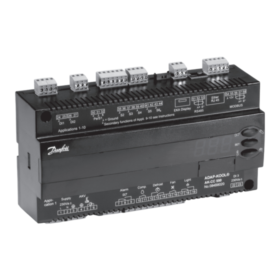
- Page 1 Controller for appliance control AK-CC 550 Manual...
-
Page 2: Table Of Contents
• Start of defrost via schedule, digital input or network • Natural, electric or hot gas defrost • Stop of defrost on time and/or temperature • Coordination of defrosting among several controls • Pulsing of fans when thermostat is satisfied • Case cleaning function for documentation of HACCP procedure • Rail heat control via day/night load or dew point • Door function • Control of two compressors • Control of night blinds • Light control • Heat thermostat • Factory calibration that will guarantee a better measuring accu- racy than stated in the standard EN 441-13 without subsequent calibration (Pt 1000 ohm sensor) • Integrated MODBUS communication with the option of mount- ing a LonWorks communication card Appliance examples Manual RS8EN502 © Danfoss 02-2010 AK-CC 550... - Page 3 Here the temperature and alarm monitoring are always controlled using the S4 sensor. The S3 sensor is used for display readings. The product sensor is replaced by an extra defrosting sensor S5B for the second evaporator. Application 10 This use is for refrigeration appliances with one valve, one evapo- rator and two refrigeration sections. Here temperature is always controlled using the S4 temperature. The S6 sensor is placed in the S3B position. The S3B sensor uses alarm limits, etc which are normally used for the S6 sensor. The two S3 temperatures are used for alarm monitoring and display readings for each refrigeration section. There are separate alarm limits for each refrigeration section. AK-CC 550 Manual RS8EN502 © Danfoss 02-2010...
-
Page 4: Operation
Use of the S1 sensor means that location is particularly impor- tant. The sensor must be located so as to read the evaporating temperature during injection without the presence of too much pressure drop. Danfoss recommends that the S1 sensor be located on the first pipe bend on the evaporator. Temperature control The temperature in the appliance is registered by one or two temperature sensors which are located in the air flow before the evaporator (S3) or after the evaporator (S4) respectively. A setting... - Page 5 A later processing of these alarms will document that the appliance has been cleaned as often as planned. Alarm monitoring There are no temperature alarms during appliance cleaning. AK-CC 550 Manual RS8EN502 © Danfoss 02-2010...
- Page 6 Schedule: Here defrost can be started at fixed times of the day and night. However, max. 6 times Contact: Defrost is started with a contact signal on a digital input Network: The signal for defrost is received from a system unit via the data communication Adaptive defrost: Here defrosting is started based on intelligent registering of evaporator performance. Manual: An extra defrost can be activated from the controller’s lower-most button All the mentioned methods can be used at random – if just of them is activated a defrost will be started. Stop of defrost Defrosting can be stopped by either: • Time • Temperature (with time as safety). Manual RS8EN502 © Danfoss 02-2010 AK-CC 550...
- Page 7 If the controller is equipped with data communication, the clock remained in the range between -5°C and +10°C for a longer will automatically be updated from the system unit. period than the set melting interval. The refrigeration will then be stopped during the set melting period. The frost will be melted so that the air flow and hence the evaporator’s capacity will be greatly improved. AK-CC 550 Manual RS8EN502 © Danfoss 02-2010...
- Page 8 ON period is controlled from the current dew point. Two dew point values are set in the appliance control: • One where the effect must be max. i.e.100%. (o87) • One where the effect must be min. (o86). At a dew point which is equal to or lower than the value in 086, the effect will be the value indicated in o88. In the area between the two dew point values the controller will manage the power to be supplied to the rail heat. Dew point During defrosting During defrosting the rail heat will always be 100% ON. Manual RS8EN502 © Danfoss 02-2010 AK-CC 550...
- Page 9 When the night blinds are closed, it is possible to open them using a switch signal on the digital input. If this input is activated, the night blinds will open and the refrigeration appliance can be filled with new products. If the input is activated again, the blinds close again. When the night blind function is used, the thermostat function can control with different weighting between the S3 and S4 sensors. A weighting during day operation and another when the blind is closed. A night blind is open when the appliance cleaning function is activated. A setting can define that the night blind is open when "r12" (Main switch) is set to off (see o98). AK-CC 550 Manual RS8EN502 © Danfoss 02-2010...
- Page 10 The difference for the heating thermostat has the same value Neutral zone as for the refrigeration thermostat. To prevent that the heating thermostat cuts in during short-term drops in air temperature a time delay can be set for when to change from refrigeration to Heat heating. Manual RS8EN502 © Danfoss 02-2010 AK-CC 550...
- Page 11 See literature: RC8AC. Override The controller contains a number of functions which can be used together with the override function in the master gateway/system manager. Function via data communication Function in gateway/system manager Used parameters in AK-CC 550 Start of defrosting Defrost control / Time schedule / Defrost group --- Def start Coordinated defrost Defrost control / Defrost group --- HoldAfterDef / - - - DefrostState Prevent defrost start...
- Page 12 The ten uses are all adapted for commercial refrigeration systems in the form of either refrigeration appliances or cold storage rooms. In general all have outputs for: • AKV valve • Fan • Defrost In addition they have different uses and thereby input and outputs. Application 1-4 Standard applications. This is for standard use where the vital difference is only different combinations of the following functions/outputs: • Alarm • Rail heat • Compressor • Light Manual RS8EN502 © Danfoss 02-2010 AK-CC 550...
- Page 13 The temperature is controlled and is always alarm monitored according to the S4 temperature. For this the product sensor is used as a defrosting stop sensor for evaporator no. 2. Application 10 Two refrigeration sections – individual alarm/ display via S3 This application is for refrigeration appliances with one valve, one evaporator and two refrigeration sections. The temperature is always controlled according to the S4 temperature. The product sensor is used as an extra S3 sensor for section no. 2. Alarm monitoring and display readings take place individually via the "S3" sensors in each refrigeration section. AK-CC 550 Manual RS8EN502 © Danfoss 02-2010...
- Page 14 Connection signs The controller is provided with signs from the factory indicating application 1. If you employ another use, signs are provided so that you can mount the relevant one. It is only the lower sign that needs to be mounted. The number is indicated on the left-hand side of the signs. Use the sign with the current application number. One of the signs applies to both applications 4 and 10. Manual RS8EN502 © Danfoss 02-2010 AK-CC 550...
- Page 15 Therm. mode Here it is defined how the thermostat is to operate. Either as an ordinary ON/OFF ther- mostat or as a modulating thermostat. 1: ON/OFF thermostat 2: Modulating When operation is ”modulating” the AKV valve will limit the flow of refrigerant so that the temperature variation will be less than for the ON/OFF thermostat. The differential (r01) must not be set lower than 2K for "modulating". In a decentralised plant you must select the ON/OFF thermostat setting. Selection of thermostat sensor Ther. S4 % Here you define the sensor the thermostat is to use for its control function. S3, S4, or a combination of them. With the setting 0%, only S3 is used (Sin). With 100%, only S4. Melt function MeltInterval Only for control of refrigeration (-5 to +10°C). The function ensures that the evapora- tor will not be blocked by frost. Here you set how often the function is to stop the refrigeration and hence transform the frost to water (or ice if there is too much frost). Melt period Melt period Here you set how long an on-going melt function is to last. AK-CC 550 Manual RS8EN502 © Danfoss 02-2010...
- Page 16 This time delay is used for start-up, during defrosting, immediately after a defrost and after an appliance clean. A change is carried out to standard time delay (A26) when the temperature has reached below the set upper alarm limit. The time delay is set in minutes. Reset alarm Ctrl. Error (EKC error) Manual RS8EN502 © Danfoss 02-2010 AK-CC 550...
- Page 17 Time staggering for defrost cutins during start-up Time Stagg. The function is only relevant if you have several refrigeration appliances or groups where you want the defrost to be staggered in relation to one another. The function is furthermore only relevant if you have chosen defrost with interval start (d03). The function delays the interval time d03 by the set number of minutes, but it only does it once, and this at the very first defrost taking place when voltage is connected to the controller. The function will be active after each and every power failure. AK-CC 550 Manual RS8EN502 © Danfoss 02-2010...
- Page 18 Integration time Tn sec Expert setting for injection function The value should only be changed by specially trained staff. Max. value for the superheat reference Max SH Min. value for the superheat reference Min SH MOP temperature MOP temp If no MOP function is required, select pos. OFF (A value of 15 corresponds to OFF) Temperatureglide (only when using of S1-temperature sensor) Glide If a zeotrope refrigerant is used, a value for temperature glide must be set. Manual RS8EN502 © Danfoss 02-2010 AK-CC 550...
- Page 19 Real-time clock You can set up to six individual times for defrost starts for each 24-hour period. There is also a date indication used for registration of temperature measurements. Defrost start, hour setting t01-t06 Defrost start, minute setting (1 and 11 belong together, etc.) t11-t16 When all t01 to t16 equal 0 the clock will not start defrosts. Clock: Hour setting Clock: Minute setting Clock: Date setting Clock: Month setting Clock: Year setting AK-CC 550 Manual RS8EN502 © Danfoss 02-2010...
- Page 20 S3, S4, or a combination of the two. With setting 0% only S3 is used. With 100% only S4. MinTransPres Pe. Working range for pressure transmitter - min. value MaxTransPres Pe. Working range for pressure transmitter - max. value Refrigerant setting (only if "r12" = 0) Refrigerant Before refrigeration is started, the refrigerant must be defined. You may choose be- tween the following refrigerants 1=R12. 2=R22. 3=R134a. 4=R502. 5=R717. 6=R13. 7=R13b1. 8=R23. 9=R500. 10=R503. 11=R114. 12=R142b. 13=Userdefined. 14=R32. 15=R227. 16=R401A. 17=R507. 18=R402A. 19=R404A. 20=R407C. 21=R407A. 22=R407B. 23=R410A. 24=R170. 25=R290. 26=R600. 27=R600a. 28=R744. 29=R1270. 30=R417A. 31=R422A Warning: Wrong selection of refrigerant may cause damage to the compressor. Other refrigerants: Here Setting 13 is selected and then three factors -Ref.Fac a1, a2 and a3 - via AKM must be set. Manual RS8EN502 © Danfoss 02-2010 AK-CC 550...
- Page 21 Access code 2 (Access to adjustments) Acc. code 2 There is access to adjustments of values, but not to configuration settings. If the set- tings in the controller are to be protected with an access code you can set a numeri- cal value between 0 and 100. If not, you can cancel the function with setting 0. If the function is used, access code 1 (o05) must also be used. Save as factory setting With this setting you save the controller’s actual settings as a new basic setting (the earlier factory settings are overwritten). AK-CC 550 Manual RS8EN502 © Danfoss 02-2010...
- Page 22 Display of temperature during normal operation Disp. Ctrl. 1: Air temperature. Weighted S3 + S4 2: Product temperature S6 Light and night blinds definition Light MS = Off 0: Light is switched off and night blinds are open when the main switch is off 1: Light and night blinds are independent of main switch. Configuration of the alarm relay Al.Rel. Conf. The alarm relay will be activated upon an alarm signal from the following groups: 1 - High temperature alarms 2 - Low temperature alarms 4 - Sensor error 8 - Digital input is activated for alarm 16 - Defrost alarms 32 - Miscellaneous 64 - Injection alarms The groups that are to activate the alarm relay must be set by using a numerical value which is the sum of the groups that must be activated. (E.g. a value of 5 will activate all high temperature alarms and all sensor errors) Manual RS8EN502 © Danfoss 02-2010 AK-CC 550...
- Page 23 2= Thermostat 2 DI3 status Status on input DI3 (on/1 = 230 V) Cutin temp. Readout of the actual cutin value for the thermostat Cutout temp. Readout of the actual cut out value for the thermostat AD state Status on function "Adaptive defrost" 0: Off. Function is not activated 1: Error. A reset must be carried out using d22 2: Reset is activated. New tuning is in progress 3: Normal 4: Light build-up of ice 5: Medium build-up of ice 6: Heavy build-up of ice *) Not all will be displayed. Only the function belonging to the selection application is displayed. AK-CC 550 Manual RS8EN502 © Danfoss 02-2010...
- Page 24 Manual control of outputs No refrigerant selected Case cleaning Forced cooling Delay on outputs during start-up Heat function r36 is active Other displays: The defrost temperature cannot be displayed. There is stop based on time Defrost in progress / First cooling after defrost Password required. Set password Regulation is stopped via main switch *) Emergency cooling will take effect when there is lack of signal from a defined S3 or S4 sensor. The regulation will continue with a registered average cutin frequency. There are two registered values – one for day operation and one for night operation. Manual RS8EN502 © Danfoss 02-2010 AK-CC 550...
- Page 25 Error on S5B sensor ---/--- Max Def.Time Defrost stopped based on time instead of, as wanted, on temperature Data communication The importance of individual alarms can be defined with a setting. The setting must be carried out in the group "Alarm destinations" Settings from Settings from Alarm relay Send via High Low-High System manager AKM (AKM destination) Network High Middle Log only Disabled AK-CC 550 Manual RS8EN502 © Danfoss 02-2010...
-
Page 26: Operation
Cutout alarm relay / receipt alarm/see alarm code • A short press of the upper button If there are several alarm codes they are found in a rolling stack. Push the uppermost or lowermost button to scan the rolling stack. Set temperature 1. Push the middle button until the temperature value is shown 2. Push the upper or the lower button and select the new value 3. Push the middle button again to conclude the setting. Reading the temperature at defrost sensor (Or product sensor, if selected in o92.) • A short press of the lower button Manuel start or stop of a defrost • Push the lower button for four seconds. Manual RS8EN502 © Danfoss 02-2010 AK-CC 550... - Page 27 -20°C Min. temp. setting (r03) 0°C -4°C -30°C 0°C -2°C -24°C Sensor signal for thermostat. S4% (r15) 100% Alarm limit high (A13) 8°C 6°C -15°C 10°C 8°C -15°C Alarm limit low (A14) -5°C -5°C -30°C 0°C 0°C -30°C Sensor signal for alarm funct.S4% (A36) 100% Interval between defrost (d03) Defrost sensor: 0=time, 1=S5, 2=S4 (d10) DI1 config. (o02) Case cleaning (=10) Door function (=2) Sensor signal for display view S4% (017) Note: For applications 9 and 10 the sensor weighting for the S3/S4 sensors is not used for the thermostat, alarm thermostat and display readings as the sensor uses are predefined. AK-CC 550 Manual RS8EN502 © Danfoss 02-2010...
-
Page 28: Menu Survey
0 min. 60 min. Delay for fan start after defrost 0 min. 60 min. Fan start temperature -50 °C 0 °C Fan cutin during defrost 0: Stopped 1: Running 2: Running during pump down and defrost Defrost sensor: 0 =Stop on time, 1=S5, 2=S4, 3=Sx (Application 1-8 and 10: both S5 and S6. Application 9: S5 and S5B) Manual RS8EN502 © Danfoss 02-2010 AK-CC 550... - Page 29 Network address On/Off switch (Service Pin message) 0/Off 1/On 0/Off IMPORTANT! o61 must be set prior to o04 (used at LON 485 only) Access code 1 (all settings) : 0=Pt1000, 1=Ptc1000, 0/Pt 1/Ptc 0/Pt Used sensor type Max hold time after coordinated defrost 0 min. 360 min. Select signal for display view. S4% (100%=S4, 0%=S3) 100 % Pressure transmitter working range – min. value -1 bar 5 bar Pressure transmitter working range – max. value 6 bar 200 bar AK-CC 550 Manual RS8EN502 © Danfoss 02-2010...
- Page 30 1/yes 1/yes no/0=Fan Off, yes/1=Fan On Definition of readings on lower button: 1=defrost stop temperature, 2=S6 temperature, 3=S5_B temperature Display of temperature 1= u56 Air temperature 2= u36 product temperature Light and night blinds defined 0: Light is switch off and night blind is open when the main switch is off 1: Light and night blind is independent of main switch Configuration of alarm relay The alarm relay will be activated upon an alarm signal from the following groups: 1 - High temperature alarms 2 - Low temperature alarms 4 - Sensor error 8 - Digital input is activated for alarm 16 - Defrost alarms 32 - Miscellaneous 64 - Injection alarms The groups that are to activate the alarm relay must be set by using a numerical value which is the sum of the groups that must be activated. (E.g. a value of 5 will activate all high temperature alarms and all sensor errors) Manual RS8EN502 © Danfoss 02-2010 AK-CC 550...
- Page 31 1: Thermostat 1 operating, 2: Thermostat 2 operating Status on high voltage input DI3 Readout of thermostats actual cut in value Readout of thermostats actual cut out value Readout of status on the adaptive defrost 0: Off. Function is not activated 1: Error. A reset must be carried out using d22 2: Reset is activated. New tuning is in progress 3: Normal 4: Light build-up of ice 5: Medium build-up of ice 6: Heavy build-up of ice *) Can only be set when regulation is stopped (r12=0) **) Can be controlled manually, but only when r12=-1 ***) With access code 2 the access to these menus will be limited AK-CC 550 Manual RS8EN502 © Danfoss 02-2010...
-
Page 32: Applications
S4, air sensor, placed in the cold air after the evaporator Supply voltage (the need for either S3 or S4 can be deselected in the 230 V a.c. configuration) S5, defrost sensor, placed on the evaporator S6, product sensor or defrost sensor B or air sensor B. The configuration determines which. Manual RS8EN502 © Danfoss 02-2010 AK-CC 550... - Page 33 There is connection between terminal 13 and 14 during normal present problems. Electronic controls are no substitute for normal, operation. good engineering practice. There is connection between terminal 12 and 14 when the hot Danfoss will not be responsible for any goods, or plant compo- gas valves must open. nents, damaged as a result of the above defects. It is the installer's responsibility to check the installation thoroughly, and to fit the necessary safety devices. Special reference is made to the necessity of signals to the...
-
Page 34: Data
230 V a.c. coil Environments 20 - 80% Rh, not condensed No shock influence / vibrations Density IP 20 Mounting DIN-rail or wall Weight 0.4 Kg Fixed MODBUS LON RS485 Data Extension options TCP/IP communication MODBUS The controller cannot be hooked up with a monitor- ing unit type m2. Power reserve 4 hours for the clock EU Low Voltage Directive and EMC demands re CE- marking complied with Approvals LVD tested acc. EN 60730-1 and EN 60730-2-9, A1, A2 EMC tested acc. EN50082-1 and EN 60730-2-9, A2 * DO3 and DO4 are 16 A relays. DO2, DO5 and DO6 are 8 A relays. Max. load must be observed. Manual RS8EN502 © Danfoss 02-2010 AK-CC 550... -
Page 35: Ordering
External display with operation buttons and screw terminals Examples of order Installation Data communication Connection Code no. MODBUS 084B8020 (AK-CC 550) 084B8020 084B8579 DANBUSS 084B8020 084B8583 MODBUS 084B8020 084B8574 (Display) 084B7299 (Cable, 6 m) LON / DANBUSS 084B8020 084B8574 (Display) 084B7299 (Cable, 6 m) 084Bxxxx (Data module) L < 15 m MODBUS / LON / DANBUSS 084B8020 084B8562 (Display) 084Bxxxx (Data module) L > 15 m AK-CC 550 Manual RS8EN502 © Danfoss 02-2010... - Page 36 Danfoss can accept no responsibility for possible errors in catalogues, brochures and other printed material. Danfoss reserves the right to alter its products without notice. This also applies to products already on order provided that such alternations can be made without subsequential changes being necessary in specifications already agreed. All trademarks in this material are property of the respecitve companies. Danfoss and Danfoss logotype are trademarks of Danfoss A/S. All rights reserved. Manual RS8EN502 © Danfoss 02-2010 AK-CC 550...
Need help?
Do you have a question about the AK-CC 550 and is the answer not in the manual?
Questions and answers