
Related Manuals for KYE Systems Corp. Genius SW-2.1 360


Summary of Contents for KYE Systems Corp. Genius SW-2.1 360
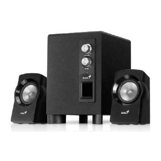
- Page 1 Service Manual SW-2.1 360 Service Manual KEY SYSTEM CORP Version No.:1.0 Page:1 of 19...
- Page 2 Service Manual SW-2.1 360 Revision history: Version Date Revision 2011-8-18 Version No.:1.0 Page:2 of 19...
-
Page 3: Table Of Contents
Service Manual SW-2.1 360 Contents File Version……………………………………………………………2 Contents…………………………………………………………………3 Getting Started……………………………………………………….4 Operating Guide…………………………………………………….4 Safety Precautions………………………………………………..4 Chapter I. Handling the returned defective products…………5 1.2 Fault…………………………………………………………….6 1.2.1 Power& indicator failure………………………………7 1.2.2 No sound……………………………………………………8 1.2.3 No L/R output…………………………………………….9 1.2.4 No bass……………………………………………………10 1.2.5 Noise & cacophony………………………………………11 1.2.6 Power indicator failure………………………………12 Chapter II. -
Page 4: Getting Started
Service Manual SW-2.1 360 Getting Started Operating Guide Special note: This Guide helps users to remember and prevent mistakes. Warning: The product may be damaged if the information is disallowed. Safety Precautions The following precautions should be followed while operating the sound box; The product should be laid flat. -
Page 5: Chapter I. Handling The Returned Defective Products
Service Manual SW-2.1 360 Chapter I. Handling the returned defective products 1.1 Overview Receive the sound box returned by a customer Verify the problem with necessary tests If the problem exists Analyze the possible reason Define an effective service plan Test result: NG Test result: OK Replace the defective... -
Page 6: 1.2 Fault
Service Manual SW-2.1 360 1.2 Fault Problem 1.2.1 Power/LED indicator failure 1.2.2 No sound 1.2.3 No L/R output 1.2.4 No bass 1.2.5 Noise and cacophony 1.2.6 LED indicator failure Version No.:1.0 Page:6 of 19... - Page 7 Service Manual SW-2.1 360 * Note Please follow the single flow chart. It is the best sequence recommended to solve the problem. 1.2.1Power/LED indicator failure Power/LED indicator failure 1. The power cord is 1.The power cord is welded defective or damaged; improperly/loosely or broken;...
- Page 8 Service Manual SW-2.1 360 1.2.2No sound No sound 1. The potentiometer 1. The PCB is short- 1. The audio VR1 is damaged; circuited/broken or processor unit of the has no supply; PCB is damaged; 2. The circuit board 2. The connection IC1/IC2/ is connected loosely, wire is damaged or...
- Page 9 Service Manual SW-2.1 360 1.2.3No L/R output No L/R output 1. The PCB is short- 1. The component of 1. The L/R speaker circuited/broken/dam L/R channel aged; IC1, IC2, Q, damaged/defective; 2. The VR1 VR1, potentiometer is CON2B/CON3/CON1 defective; 2. The L/R output 3.
- Page 10 Service Manual SW-2.1 360 1.2.4No bass No bass 1. The PCB is 1. The bass control 1. The damaged; circuit fails; component(s) from 2. The PCB is short- 2. The speaker is IC2, VR2 and the circuited. defective; bass unit 3.
- Page 11 Service Manual SW-2.1 360 1.2.5Noise and cacophony Noise and cacophony The signal line is 1. The power supply 1. The potentiometer improperly grounded; is poor, causing is used for over long CON2B/signal line is damage to the filter time, causing bad defective capacitor and great contact...
- Page 12 Service Manual SW-2.1 360 1.2.6LED indicator failure LED indicator failure 1. The LED1 is damaged or does not illuminate; 2. The copper foil of the lamp base on the PCB is broken; 3. The R15 is defective. Replace/repair Version No.:1.0 Page:12 of 19...
-
Page 13: Chapter Ii. Specification
Service Manual SW-2.1 360 Chapter II. Specification Version No.:1.0 Page:13 of 19... - Page 14 Service Manual SW-2.1 360 Chapter III. Block Chart Block Chart Signal input Power supply Master volume Bass adjustment adjustment Power amplifier Power amplifier TEA2025B TEA2025B Bass output Version No.:1.0 Page:14 of 19...
-
Page 15: Subwoofer
Service Manual SW-2.1 360 Chapter IV. Assembly Rendering Subwoofer: Version No.:1.0 Page:15 of 19... -
Page 16: Satellite
Service Manual SW-2.1 360 Satellite: Version No.:1.0 Page:16 of 19... -
Page 17: Subwoofer
Service Manual SW-2.1 360 Chapter V. List of Parts Subwoofer: Ref. NO Description Part NO. KNOB AMP014913.00G FRONT PANEL AMP014901.09G VOLUME PCBA ASP014906.G01 WRAP BOARD(CE) AHB014905.00G WRAP BOARD(UL) AHB014905.01G POWER PCBA AEM100024.00G HEAT SINK AHS000053.00G METAL BAR AMB000006.00G BACK PANEL AMP702313.00G PAPER TUBE AHC000016.00G... -
Page 18: Satellite
Service Manual SW-2.1 360 Satellite: Ref. NO Description Part NO. FRONT CABINET AMP014903.15G SPEAKER AMK340047.G01 BACK CABINET AMP714902.00G RUBBER FOOT AHR000059.00G Version No.:1.0 Page:18 of 19... -
Page 19: Chapter Vi. Electric Schematic Diagram
Service Manual SW-2.1 360 Chapter VI. Electric Schematic Diagram Version No.:1.0 Page:19 of 19...
Need help?
Do you have a question about the Genius SW-2.1 360 and is the answer not in the manual?
Questions and answers