Table of Contents
Advertisement
Advertisement
Table of Contents

Related Manuals for Aerogen Aeroneb Pro


Summary of Contents for Aerogen Aeroneb Pro
- Page 1 Instruction Manual...
- Page 3 ® Aeroneb Professional Nebulizer System Instruction Manual...
- Page 4 This page has been intentionally left blank...
-
Page 5: Table Of Contents
Table of contents Introduction................1 System description ............. 2 Warnings ................4 Warnings ................5 Electromagnetic susceptibility ..........6 Warnings ................7 Symbols ................8 Warranty................12 Life of Product ..............12 Assembly and Installation ............. 13 Recharging the Battery ............ 15 Installation for use with a ventilator ........ - Page 6 Figure 17: Starting and stopping nebulization....... 26 List of Tables Table 1: Aeroneb Pro symbols ..........8 Table 2: Aeroneb Pro controls and indicators ....... 11 Table 3: Aeroneb Pro troubleshooting ........34 Table 4: Aeroneb Pro parts list ..........37 ®...
-
Page 7: Introduction
® Aeroneb Pro is suitable for use by neonate, pediatric to adult patients as described in this manual. It incorporates the ® Aerogen Vibronic Aerosol Generator. ® Aeroneb Pro is intended for hospital use only. It is designed to operate in-line with standard ventilator circuits and mechanical ventilators. -
Page 8: System Description
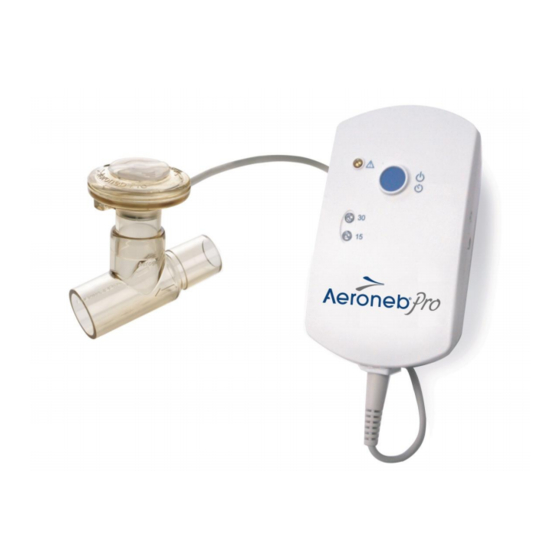
2. T-piece (adult) with plug 1. Nebulizer unit with filler cap 4. Control Module Cable 3. Control module 5. AC/DC adapter 6. Universal mounting bracket 7. Equipment mount adapter Figure 1: Aeroneb Pro ® Aeroneb Professional Nebulizer System Instruction Manual... - Page 9 ® Within the nebulizer unit is an Aerogen Vibronic Aerosol Generator, which consists of a domed aperture plate with precision-formed holes that control the size of the aerosol droplets and a vibrational element that creates micro-pumping action to aerosolize medication.
-
Page 10: Warnings
Warnings Read and study all instructions before using Aeroneb Pro. Only medical personnel should operate the device. During use observe for correct functioning of the nebulizer by regularly verifying aerosol is visible and no flashing indicator lights. Do not use a filter or heat-moisture exchanger (HME) between the nebulizer and patient airway. -
Page 11: Warnings
Inspect all parts before use, and do not use if any parts are missing, cracked or damaged. In case of missing parts, malfunction or damage, contact your Aeroneb Pro nebulizer system sales representative. Disconnect nebulizer unit from control module before cleaning. -
Page 12: Electromagnetic Susceptibility
Do not use in the presence of devices generating high electromagnetic fields such as magnetic resonance imaging (MRI) equipment. The Aeroneb Pro control module contains a nickel metal hydride (NiMH) rechargeable battery, which should be disposed of in accordance with local governing restrictions at the end of its useful life. -
Page 13: Warnings
Aeroneb Pro nebulizer system. Do not use the Aeroneb Pro adjacent to or stacked with other equipment. If adjacent or stacked use is necessary, the device should be observed to verify normal operation in this configuration. -
Page 14: Symbols
Symbols The following symbols apply to Aeroneb Pro and appear on the back of the control module and on the packaging: Table 1: Aeroneb Pro symbols Symbol Meaning Serial number, where YY is the year of AP-YYXXXX manufacture and XXXX is the serial number. - Page 15 Table 1: Aeroneb Pro symbols Symbol Meaning Does not contain natural rubber latex. Battery status indicator. Fragile, handle with care. +60C Transient storage temperature limitations –20 C to +60 C. -20C Keep dry. This device complies with the requirements of the Medical Devices Directive (93/42/EEC).
-
Page 16: Figure 2: Aeroneb Pro Controls And Indicators
Controls and indicators On/Off Power Fault Indicator Timer Selection 30 Min. Indicator Battery Status Indicator 15 Min. Indicator 9V D.C. Input Control Module Cable Input Figure 2: Aeroneb Pro controls and indicators ® Aeroneb Professional Nebulizer System Instruction Manual... -
Page 17: Table 2: Aeroneb Pro Controls And Indicators
Table 2: Aeroneb Pro controls and indicators Control/indicator Function Green (steadily lit) = 15 minute 15 Min. indicator nebulization cycle on Green (flashing) = Low battery power Nebulizer unit automatically powers off after 15 minutes have elapsed ... -
Page 18: Warranty
Warranty The Aeroneb Pro nebulizer unit is warranted for one year from date of purchase against defects in manufacturing. The Aeroneb Pro Control Module and AC/DC Adapter are warranted for a period of two years from the date of purchase against defects in manufacturing. -
Page 19: Assembly And Installation
Note: The nebulizer unit and T-piece, as packaged, are not sterile. 2. Perform a functional test of Aeroneb Pro before use and between patients as described in the functional test section of this manual. 3. Insert the filler cap into the opening on the nebulizer unit. -
Page 20: Figure 4: Connecting Control Module And Nebulizer Unit
AC/DC adapter connector into the control module and plug the adapter into an AC power source (Figure 5). 7. Aeroneb Pro can be battery-operated for portable applications. The rechargeable battery can power the System for up to 45 minutes when fully charged. In the case of AC power failure the control module will automatically switch to battery operation. -
Page 21: Recharging The Battery
Figure 5: Connecting the AC/DC adapter Recharging the Battery To recharge the battery, connect the AC/DC adapter to the control module and AC power (Figure 5). The battery status indicator is amber while charging and green when fully charged. Allow a minimum of four hours for the internal battery to fully recharge. -
Page 22: Installation For Use With A Ventilator
Always visually inspect the nebulizer prior to placing in the ventilator circuit to assure that no ® secretions are blocking the Aerogen Vibronic Aerosol Generator. When removing the nebulizer unit from the patient circuit always replace the T-piece plug to maintain circuit pressure. -
Page 23: Figure 6: Connecting To An Adult Breathing Circuit
ADULT From ventilator Adult T-piece Figure 6: Connecting to an adult breathing circuit PEDIATRIC From ventilator Pediatric T-piece Figure 7: Connecting to a pediatric breathing circuit Neonate adapters NEONATE From ventilator Pediatric T-piece ® Aeroneb Professional Nebulizer System Instruction Manual... -
Page 24: Figure 8: Connecting To A Neonatal Breathing Circuit
Figure 8: Connecting to a neonatal breathing circuit From ventilator Neonate T-Piece Figure 9: Alternative neonatal breathing circuit using neonate T-piece 2. Always perform a leak test of the breathing circuit after inserting or removing the nebulizer unit. Follow ventilator manufacturer instructions for performing a leak test. -
Page 25: Figure 10: Control Module And Universal Mounting Bracket (Vertical)
Figure 10: Control module and universal mounting bracket (vertical) Figure 11: Control module and universal mounting bracket (horizontal) Standard equipment mount Figure 12: Equipment mount adapter ® Aeroneb Professional Nebulizer System Instruction Manual... -
Page 26: Installation For Use With A Mask
Installation for use with a mask Mask kits, which include a vented elbow and mask elbow, are available separately (see Order numbers section). Contact your Aeroneb Pro nebulizer system sales representative for ordering information. 1. When using a mask, connect the vented elbow, mask elbow and mask to the nebulizer unit by firmly pushing the parts together. -
Page 27: Figure 13: Connecting To A Mask
Facemask Elbow Vented Elbow Patient Upright Patient Reclined Figure 13: Connecting to a mask ® Aeroneb Professional Nebulizer System Instruction Manual... -
Page 28: Installation For Use With A Mouthpiece
Installation for use with a mouthpiece Aeroneb Pro works with any standard ISO 22 mm nebulizer mouthpiece inserted into the adult T-piece. When using a mouthpiece, connect the nebulizer unit to the T-piece as shown in Figure 3 in this manual, and then connect the T-piece to the mouthpiece by pushing the parts firmly together (Figure 14). -
Page 29: Adding Medication
Adding medication 1. Open the filler cap tab on the nebulizer unit. 2. Use a pre-filled ampoule or syringe to add medication into the filler port of the nebulizer (Figure 15). 3. Close the filler cap tab. CAUTION: To avoid damage to the nebulizer unit, do not use a syringe with needle. -
Page 30: Figure 16: Maximum Fill Indication Point
Max. fill indication point Figure 16: Maximum fill indication point ® Aeroneb Professional Nebulizer System Instruction Manual... -
Page 31: Nebulization
Nebulization For doses less than or equal to 3 mL. 1. To start a 15 minute nebulization cycle, add the medication and press and release the blue On/Off power button (Figure 17). The green 15 Min. indicator lights to indicate that the 15 minute nebulization cycle is in progress. -
Page 32: Figure 17: Starting And Stopping Nebulization
On/Off Power Button Press and release to select 15 min Press and hold for three seconds to select 30 min. 30 Min. Indicator 15 Min. Indicator Figure 17: Starting and stopping nebulization ® Aeroneb Professional Nebulizer System Instruction Manual... -
Page 33: Functional Test
Functional test Perform a functional test of Aeroneb Pro prior to first use, after each sterilization before each patient use or at any time to verify proper operation. Follow these steps: 1. Visually inspect each part of the System for cracks or damage and replace if any defects are visible. -
Page 34: Cleaning, Disinfection And Sterilization
Cleaning, disinfection and sterilization This section describes how to clean, disinfect, sterilize and inspect Aeroneb Pro system components. It is important that Aeroneb Pro device components are cleaned and sterilized prior to first patient use. The components are: Nebulizer unit (including filler cap) ... - Page 35 CAUTION: Do not use abrasive or sharp tools to clean the nebulizer unit. Automated Washing Cycle The Aeroneb Pro Nebulizer System has been validated with the following automated washing cycles. Automated Cycle One: Detergent: Liquid alkaline cleaner (diluted as per...
- Page 36 NOTE: Aerogen approves the following disinfection solutions for use with its Aeroneb Pro Nebulization System regarding material compatibility. With respect to microbiological effectiveness, please ask the manufacturer. Refer to the product labeling for specific instructions regarding activation, safe use and disposal of these solutions.
- Page 37 Sterilization of nebulizer unit, T-pieces and neonate adapters 1. Disconnect the nebulizer unit from the control module, and then remove the nebulizer unit and adapters from the ventilator circuit, mask or mouthpiece. 2. Disassemble the nebulizer unit and adapters into individual components.
- Page 38 NOTE: Sterilization using the long autoclave cycle ((iii) above) may cause some areas of the nebulizer to become discolored. This is not indicative of the performance of the nebulizer unit. To sterilize with hydrogen peroxide gas plasma, ® place wrapped parts in a STERRAD System, and use the long cycle.
- Page 39 Do not use abrasive or sharp tools. Do not spray liquid directly onto the control module. Do not immerse control module in liquid. Caution: The Aeroneb Pro nebulizer unit contains active electronic components. Aerogen has validated the methods of cleaning, disinfection and sterilization above.
-
Page 40: Troubleshooting
Troubleshooting If these suggestions do not correct the problem, discontinue use of any device that appears to be damaged or is not operating properly and contact your local Aeroneb Pro nebulizer system sales representative. Table 3: Aeroneb Pro troubleshooting If this happens:... - Page 41 Table 3: Aeroneb Pro troubleshooting If this happens: It could mean: Try this: The 15 Min. or No medication in Refill medication 30 Min. indicator nebulizer unit. through filler cap in lights, but the nebulizer unit aerosol is not (see Adding visible.
- Page 42 Life of Product. nebulizer unit. Refer to Aeroneb Pro parts list. Note: The rechargeable battery in the control module should only be replaced by Aerogen authorized personnel: contact your Aeroneb Pro nebulizer system sales representative. ® Aeroneb Professional Nebulizer System Instruction Manual...
-
Page 43: Order Numbers
Order numbers Table 4 lists the Aeroneb Pro nebulizer system order numbers (see Figure 1 for pictures) Table 4: Aeroneb Pro parts list Description Order number Aeroneb Professional Nebulizer System AG-AP6000-XX* Nebulizer unit with filler cap AG-AP1000 Silicone Plug (Pack of 5) - Page 44 Table 4: Aeroneb Pro parts list (continued) Description Order number Mask Kit, US (Pack of 5 Kits) 17 mm Male - 22 mm Male Elbow AG-AP1065 22 mm Female - 22 mm Female Vented Elbow Mask Kit, International (Pack of 5 Kits) ...
-
Page 45: Specifications
Specifications Physical Nebulizer unit dimensions: 45 mm H x 50 mm W x 50 mm D (1.8 in. H x 2.0 in. W x 2.0 in. D) Control module dimensions: 33 mm H x 75 mm W x 131 mm D (1.3 in. -
Page 46: Performance
Residual volume: < 0.1 mL for 3 mL dose Performance may vary depending upon the type of drug and nebulizer unit used. For additional information contact Aerogen or drug supplier. The temperature of the medication will not rise more than 10°C (18°F) above ambient temperature during normal use. - Page 47 Power source: can operate from AC/DC adapter (input 100 to 240 VAC 50 – 60 Hz, output 9 V) or internal rechargeable battery (4.8 V nominal output). Note: The Aeroneb Pro control module is approved for use with Aerogen AC/DC adapter AG-AP1040-xx* (Manufacturer Reference: FRIWO FW7660M4/09) Power consumption: <...
- Page 48 This page has been intentionally left blank ® Aeroneb Professional Nebulizer System Instruction Manual...
-
Page 49: Appendix 1 Emc Tables
Appendix 1 EMC Tables ® Aeroneb Professional Nebulizer System Instruction Manual... - Page 50 The Aeroneb Pro nebulizer system is intended for use in the electromagnetic environment specified below. The customer or the user of the Aeroneb Pro nebulizer system should assure that it is used in such an environment. Electromagnetic environment –...
- Page 51 Recommended separation distances between portable and mobile RF communication equipment and the Aeroneb Pro The Aeroneb Pro nebulizer system is intended for use in the electromagnetic environment in which radiated RF disturbances are controlled. The customer or the user of the Aeroneb Pro nebulizer...
- Page 52 The Aeroneb Pro nebulizer system is intended for use in the electromagnetic environment specified below. The customer or the user of the Aeroneb Pro nebulizer system should assure that it is used in such an environment. Immunity test...
- Page 53 40% Ut 40% Ut input lines If the user of (60% dip in Ut) (60% dip in Ut) the Aeroneb Pro requires continued for 5 cycles for 5 cycles EN 61000-4-11 operation during power mains 70% Ut...
- Page 54 The Aeroneb Pro nebulizer system is intended for use in the electromagnetic environment specified below. The customer or the user of the Aeroneb Pro nebulizer system should assure that it is used in such an environment. Immunity IEC/EN...
- Page 55 where P is the maximum output power rating of the transmitter in Watts (W) according to the transmitter manufacturer and d is the recommended separation distance in metres (m). Field strengths from fixed RF transmitters, as determined by an electromagnetic site survey, ª...
- Page 56 RF transmitters, an electromagnetic site survey should be considered. If the measured field strength in the location in which the Aeroneb Pro nebulizer system is used exceeds the applicable RF compliance level above, the Aeroneb Pro nebulizer system should be observed to verify normal operation.
- Page 58 Manufacturer: Aerogen Limited Galway Business Park Dangan Galway Ireland Customer Service: International: Telephone: +353 91 540400 Telephone: 1-866-423-7643 www.aerogen.com Part No. AG-AP1080-UK Rev M © 2014 Aerogen Ltd Manufacturing no.: 30-012 Rev M...
Need help?
Do you have a question about the Aeroneb Pro and is the answer not in the manual?
Questions and answers