Table of Contents
Advertisement
Quick Links
Advertisement
Table of Contents

Summary of Contents for Sunell SN-D2-F
- Page 1 Bi-Spectrum Radiometric Detector User Manual Issue V 1.0 Date 2019-10-08...
-
Page 3: Precautions
Bi-Spectrum Radiometric Detector User Manual Precautions Precautions Precautions Fully understand this document before using this device, and strictly observe rules in this document when using this device. If you install this device in public places, provide the tip "You have entered the area of electronic surveillance" in an eye- catching place. - Page 4 Bi-Spectrum Radiometric Detector Overview User Manual Use accessories delivered with this device. The voltage must meet input voltage requirements for this device. If this device is installed in places with unsteady voltage, ground this device to discharge high energy such as electrical surges in order to prevent the power supply from burning out.
- Page 5 Bi-Spectrum Radiometric Detector User Manual Precautions Keep the device away from moist, dusty, extremely hot or cold places, or places with strong electric radiation. If the device is installed outdoors, take insect- and moisture-proof measures to avoid circuit board corrosion that can affect monitoring. ...
-
Page 6: Table Of Contents
Bi-Spectrum Radiometric Detector User Manual Overview Contents Precautions ........................i 1 Overview ........................6 1.1 Principle of Thermal Imaging and Advantages .............. 6 1.2 Product Introduction ....................... 7 1.2.1 Function ......................7 1.2.2 Product Features ....................7 1.3 Description of PTZ cable ....................7 1.3.1 Multi-cable ...................... - Page 7 Bi-Spectrum Radiometric Detector User Manual Overview 5 Thermal Parameter Configuration ..............43 5.1 Access the Sensor Setting Interface ................43 5.2 Sensor Setting Parameter description ................44 5.2.1 Mode ........................ 44 5.2.2 Image Setting ....................44 5.2.3 Scene ........................ 46 5.2.4 Set Psecudocolor ....................
-
Page 8: Overview
Bi-Spectrum Radiometric Detector User Manual Overview Overview 1.1 Principle of Thermal Imaging and Advantages Any object with temperature higher than the absolute zero (-273.15°F) will emit infrared (IR) ray, even though it does not emit light. The IR ray is also called thermal radiation. -
Page 9: Product Introduction
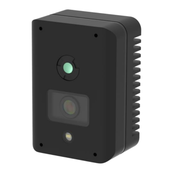
Bi-Spectrum Radiometric Detector User Manual Overview 1.2 Product Introduction Bi-Spectrum Radiometric Detector, the whole machine shell and the base are all made of high strength aluminum alloy material with comprehensive function and high stability. It can be widely used in power switch cabinets, machine rooms, storages, etc. - Page 10 Bi-Spectrum Radiometric Detector User Manual Overview Figure 1-1 Aviation power supply and network cable Table 1-1 Description of cores Port Description Power DC 12 V Connect USB port Connect to video screen Video port Ground earth wire Network port Connect to a standard Ethernet cable Orange RS232 RX Blue...
-
Page 11: Device Dimensions
Bi-Spectrum Radiometric Detector User Manual Device Dimensions Device Dimensions Figure 2-1 shows the dimensions of the Bi-Spectrum Radiometric Detector。 Issue V1.0 (2019-10-08) - Page 12 Bi-Spectrum Radiometric Detector User Manual Device Dimensions Figure 2-1 Dimensions (unit: mm) 4- M3 Depth 6 4- M3 Depth 6 2- 1/4- 20UNC- 1A Depth 8 φ55 3- φ4.5 S ym metr icall y ar ray Issue V1.0 (2019-10-08)
-
Page 13: Device Installation
Bi-Spectrum Radiometric Detector User Manual Device Installation Device Installation 3.1 Cabinet Installation 3.1.1 General Installation Step 1 Stick the installation sticker label 1 on the cabinet door „s mounting surface, drill three holes based on the marks on the sticker, as shown in Figure 3-1. It is recommended that the drill size be φ3 - φ4 mm, and it is better to remove the label after the hole is finished to avoid affecting heat dissipation. - Page 14 Bi-Spectrum Radiometric Detector User Manual Device Installation Figure 3-2 Put the device Step 3 Take out the PWM3× 6 screws in the accessory and fix them on the screw holes of the camera through the hole punched in step 1 on the front of the door and tighten the screws.
-
Page 15: Magnet Installation
Bi-Spectrum Radiometric Detector User Manual Device Installation 3.1.2 Magnet Installation If you can't break the hole in the door or the camera position needs precise adjustment, you need to use the magnet bracket. Step 1 Take out the camera and the magnet bracket, install the magnet bracket on the back of the camera, and fix it with the PWM3×... -
Page 16: Walling Installation
Bi-Spectrum Radiometric Detector User Manual Device Installation ----End 3.2 Walling Installation 3.2.1 Bracket Installation If the camera angle needs to be adjusted, you need to use the gimbal bracket. Step 1 Stick the installation sticker label 3 on the walling „s mounting surface, drill three holes based on the marks on the sticker, drive three swell plastic buttons into the holes. -
Page 17: Magnet Installation
Bi-Spectrum Radiometric Detector User Manual Device Installation Figure 3-7 Install the magnet bracket Bracket nut Locking screw Step 4 Connect the multi-head combination cable to start up the camera. Step 5 Adjust the universal rod of the bracket to adjust the camera angle, tighten the bottom bracket nut and tighten the locking screw on the bracket to complete the angle adjustment. - Page 18 Bi-Spectrum Radiometric Detector User Manual Device Installation Figure 3-8 Install the magnet bracket and camera Step 3 Attach the camera assembly to the sticker position and remove the self-tapping screws to secure the camera assembly, as shown in Figure 3-9. Figure 3-9 Install the magnet bracket and camera Step 4 Connect the multi-head combination cable to start up the camera.
-
Page 19: Packing List
Bi-Spectrum Radiometric Detector User Manual Device Installation 3.3 Packing list After receiving the equipment, please follow the list of packing list to check, if there is any omission, please contact the seller. Table 3-1 Packing list Item Quantity Picture Camera Power supply and cable User manual Installation location sticker... - Page 20 Bi-Spectrum Radiometric Detector User Manual Device Installation Gimbal bracket Issue V1.0 (2019-10-08)
-
Page 21: Quick Configuration
Bi-Spectrum Radiometric Detector User Manual Quick Configuration Quick Configuration 4.1 Login and Logout You must use Internet Explorer 8 or a later version to access the web management system; otherwise, some functions may be unavailable. Login system Step 1 Open the Internet Explorer, enter the IP address of IP camera (default value: 192.168.0.120) in the address box, and press Enter. -
Page 22: Main
Bi-Spectrum Radiometric Detector User Manual Quick Configuration Logout To logout of system, click in the upper right corner of the main page, the login page is display after you log out of the system. 4.2 Main Page Layout On the main page, you can view real-time video, set parameter, Video parameter, Video control, and log out of the system. - Page 23 Bi-Spectrum Radiometric Detector User Manual Quick Configuration Figure 4-2 Main page layout (light) 9 10 11 12 13 14 Figure 4-3 Thermal live video Issue V1.0 (2019-10-08)
- Page 24 Bi-Spectrum Radiometric Detector User Manual Quick Configuration Table 4-1 Elements on the main page Element Description Real-time video Real-time videos are played in this area. You can also set area sensor parameters. Playback You can query the playback videos in this area. NOTE Only when the SD card has videos that user can query the playback videos.
-
Page 25: Change The Password
Bi-Spectrum Radiometric Detector User Manual Quick Configuration : the lowest temperature of the full screen. :the highest temperature of the full screen. : the lowest temperature of the area. : the highest temperature of the area. ----End 4.3 Change the Password Description You can click to change the password for logging in to the system. -
Page 26: Browse Video
Bi-Spectrum Radiometric Detector User Manual Quick Configuration Figure 4-4 Modify Password dialog box The change password page will be displayed if you don‟t change the default password when you login the system for the first time. Step 2 Enter the old password, new password, and confirmation password. Step 3 Click OK. - Page 27 Bi-Spectrum Radiometric Detector User Manual Quick Configuration Figure 4-5 Adding the a trusted site Step 2 In the Internet Explorer, choose Tool > Internet Options > Security > Customer level, and set Download unsigned ActiveX control and initialize and script ActiveX controls not marked as safe for scripting under ActiveX controls and plug-ins to Enable, as shown in Figure 4-6.
-
Page 28: Install Plugins
Bi-Spectrum Radiometric Detector User Manual Quick Configuration 4.5 Install Plugins You will be prompted with a message “Download and install the new plugin” as shown in Figure 4-7 when you login to the web management system for the first time. Figure 4-7 Download the plugin page Procedure Step 1... - Page 29 Bi-Spectrum Radiometric Detector User Manual Quick Configuration Figure 4-8 Local Network page Step 2 Set the parameters according to Table 4-2. Table 4-2 Local network parameters Parameter Description Setting IP Protocol IPv 4 is the IP protocol that uses [Setting method] an address length of 32 bits.
- Page 30 Bi-Spectrum Radiometric Detector User Manual Quick Configuration Parameter Description Setting Subnet Mask Subnet mask of the network [Setting method] adapter. Enter a value manually. [Default value] 255.255.255.0 Default Gateway This parameter must be set if [Setting method] the client accesses the device Enter a value manually.
-
Page 31: Thermal Settings
Bi-Spectrum Radiometric Detector User Manual Quick Configuration 4.6 Thermal Settings 4.6.1 Temperature Parameters Temperature parameters include: temperature unit, ambient type, ambient temperature, cavity temperature, correctional coefficient and area temperature display mode. Operation Procedure Step 1 Choose Configuration >Thermal >Temperature Parameters. The Temperature Parameters page is displayed, as shown in Figure 4-9. - Page 32 Bi-Spectrum Radiometric Detector User Manual Quick Configuration Parameter Description Setting Ambient The ambient temperature of [Setting method] Temperature camera. It is set when ambient Enter a value manually. is outside. Cavity The cavity temperature of Temperature camera. Correction Correction coefficient is refer to [Setting method] Coefficient the deviation of measured...
- Page 33 Bi-Spectrum Radiometric Detector User Manual Quick Configuration Parameter Description Setting Measure Mode There are two types measure [Setting method] modes. Select a value from the drop-down list box. [Default value] General Display Alarm [Setting method] Area Enable or disable [Default value] Disable Area Alarm [Setting method]...
- Page 34 Bi-Spectrum Radiometric Detector User Manual Quick Configuration Figure 4-10 Advanced interface Table 4-4 Advance parameters Parameter Description Setting Dimming Mode There are auto and manual [Setting method] modes. It will show on Select a value from the temperature item. drop-down list box. [Default value] Auto Greater Prominent...
-
Page 35: Temperature Area
Bi-Spectrum Radiometric Detector User Manual Quick Configuration Parameter Description Setting Raw Data Upload Interval of Upload the raw data. [Setting method] Interval(F/S) Select a value from the drop-down list box. [Default value] Mix Stream Mode This function is used for [Default value] thermal and visible lighting Close... - Page 36 Bi-Spectrum Radiometric Detector User Manual Quick Configuration Figure 4-11 Temperature area and alarm configuration Step 2 Set the parameters according to Table 4-5 Table 4-5 Temperature area and alarm configuration Parameter Description Setting Channel [Setting method] Select a value from the drop-down list box.
- Page 37 Bi-Spectrum Radiometric Detector User Manual Quick Configuration Parameter Description Setting Alarm Type Threshold alarm, Section Alarm [Setting method] and Temperature difference Select a value from the alarm are available for alarm drop-down list box. type. [Default value] Section Alarm: if the Threshold alarm temperature value is among the set temperature range, it will...
-
Page 38: Shield Area
Bi-Spectrum Radiometric Detector User Manual Quick Configuration Parameter Description Setting Alarm Open or close the alarm output [Setting method] and linkage of area. Tick the alarm areas area. Step 3 temperature 1. Tick an area ID. 2. Select type from drop-list. 3. -
Page 39: Schedule Linkage
Bi-Spectrum Radiometric Detector User Manual Quick Configuration Figure 4-13 Shield Area Step 2 Enable the shield area. Step 3 Enable Show Shield Area, then the setting shield will show on live video. Step 4 Click left mouse button to set area, click right mouse button to end the setting. Step 5 Click Clear to clear the shield area. -
Page 40: Thermal Mapping
Bi-Spectrum Radiometric Detector User Manual Quick Configuration Figure 4-14 Schedule Linkage Step 2 Tick the output channel. Enable “Alarm Record”, “SMTP”,”FTP” button. Step 3 Step 4 Set schedule linkage. Method 1:Click left mouse button to select any time point within 0:00-24:00 from Monday to Sunday as shown in Figure 4-14. - Page 41 Bi-Spectrum Radiometric Detector User Manual Quick Configuration Figure 4-15 Thermal mapping interface Step 2 Settings please refer to Table 4-6. Table 4-6 Parameter of thermal mapping Parameter Description Setting Zoom in /zoom out. [Setting method] Click the button Near focus / far focus. [Setting method] Click the button Lock focus...
-
Page 42: Bad Point Check
Bi-Spectrum Radiometric Detector User Manual Quick Configuration 4.6.6 Bad Point Check Description The points that can‟t move when the environment or scenario change is bad point. You can delete the bad point by bad point check function. Procedure Step 1 Choose Configuration >Thermal >... -
Page 43: Led Control Parameter
Bi-Spectrum Radiometric Detector User Manual Quick Configuration Figure 4-17 Recover bad point Step 3 Click Reset to return the previous settings. Step 4 Click Apply. The message "Apply success" is displayed, the system saves the settings. ----End 4.6.7 LED Control Parameter Procedure Step 1 Choose Configuration >Thermal >... - Page 44 Bi-Spectrum Radiometric Detector User Manual Quick Configuration Figure 4-18 LED Control Parameter Table 4-7 Parameter of thermal mapping Parameter Description Setting Display mode There are four modes, [Setting method] Close/Open/Flicker/Timing. Select from drop list. Flicker Display mode is Flicker, and [Setting method] interval(100- user need to set an interval to...
-
Page 45: Thermal Parameter Configuration
Bi-Spectrum Radiometric Detector User Manual Thermal Parameter Configuration Thermal Parameter Configuration 5.1 Access the Sensor Setting Interface Operation procedure: Step 1 On the web interface or client interface, move the cursor to the real-time video page and right-click on the page. A shortcut menu is displayed, as shown in Figure 5-1, and Table 5-1 describes the sensor setting interface. -
Page 46: Sensor Setting Parameter Description
Bi-Spectrum Radiometric Detector User Manual Thermal Parameter Configuration Step 2 Choose Sensor Configure and the Sensor Setting dialog box appears. ----End 5.2 Sensor Setting Parameter description 5.2.1 Mode Operation procedure: Step 1 Click Mode tag on sensor setting interface, the time segment page is displayed, as shown in Figure 5-2. - Page 47 Bi-Spectrum Radiometric Detector User Manual Thermal Parameter Configuration Figure 5-3 Image setting interface Table 5-2 describes the image setting parameters. Table 5-2 Image setting parameter description Parameter Description Setting Brightness It indicates the total brightness of an image. As [Setting the value increases, the image becomes brighter.
-
Page 48: Scene
Bi-Spectrum Radiometric Detector User Manual Thermal Parameter Configuration 5.2.3 Scene Figure 5-4 shows the scene interface. Figure 5-4 Scene interface Provide the selection of image pixel locations. Normal: the image is not flipped. Horizontal: the image is flipped left and right. Vertical: the image is flipped up and down. -
Page 49: Ffc Control
Bi-Spectrum Radiometric Detector User Manual Thermal Parameter Configuration Figure 5-5 set pseudocolor interface Polarity/LUT: the temperatures of the temperature fields detected by the thermal imaging camera are separately mapped to values ranging from 0 to 255 by the algorithm. In the black/white display mode, this range is converted to the grayscale tones. - Page 50 Bi-Spectrum Radiometric Detector User Manual Thermal Parameter Configuration Figure 5-6 FFC mode interface Table 5-3 describes the FFC mode parameters. Table 5-3 FFC control parameter description Parameter Description Setting The internal of the thermal imaging camera may comprise the mechanical action correction mechanism that can periodically improve the image quality.
-
Page 51: Noise Reduction
Bi-Spectrum Radiometric Detector User Manual Thermal Parameter Configuration Parameter Description Setting mode is selected, the FFC interval (minutes) ranges from 10 to 255 minutes. The temperature change of the camera is based on the temperatures collected by the internal temperature probe. The temperature of the camera sharply changes when the camera is powered on. -
Page 52: Enhance Image
Bi-Spectrum Radiometric Detector User Manual Thermal Parameter Configuration Figure 5-7 Noise reduction interface Table 5-4 describes noise reduction parameters. Table 5-4 DNR parameter description Parameter Description Setting [How to set] Select from the drop-down list box. Drag the slider to adjust max Decrease the image 2 DNR strength. - Page 53 Bi-Spectrum Radiometric Detector User Manual Thermal Parameter Configuration Figure 5-8 Enhance image interface Table 5-5 Screen adjustment parameter description Parameter Meaning Configuration Method [How to set] Drag the slider. Defog Decrease the image fog. [Default value] ----End Issue V1.0 (2019-10-08)
-
Page 54: Visible-Light Parameter Configuration
Bi-Spectrum Radiometric Detector User Manual Visible-light Parameter Configuration Visible-light Parameter Configuration 6.1 Access the Sensor Interface Operation procedure Step 1 On the web or NVMS interface, move the cursor to the real-time video page and right-click on the page. A shortcut menu is displayed, as shown in Figure 6-1. Figure 6-1 Sensor Setting interface Step 2 Choose Sensor Configure and the Sensor Setting dialog box appears. -
Page 55: Image Adjust
Bi-Spectrum Radiometric Detector User Manual Visible-light Parameter Configuration Figure 6-2 Mode page Step 2 Choose Debug Model in the lower left corner to activate the sensor setting page. Step 3 Set the time segment parameters. Step 4 Click save to save the setting. ----End 6.2.2 Image Adjust Figure 6-3 shows the Image Adjust tab page. - Page 56 Bi-Spectrum Radiometric Detector User Manual Visible-light Parameter Configuration Figure 6-3 Image Adjust tab page Table 6-1 describes the parameters on the Image Adjust tab page. Table 6-1 Parameters on the Image Adjust tab page Parameter Description Configuration Method Contrast It indicates the contrast between the bright part [Setting method] and the dark part of an image.
-
Page 57: Scene Mode
Bi-Spectrum Radiometric Detector User Manual Visible-light Parameter Configuration 6.2.3 Scene Mode Figure 6-4 shows the scene mode interface. Figure 6-4 Scene mode interface Table 6-2 describes the FFC mode parameters. Table 6-2 FFC mode parameters description Parameter Description Configuration Method It indicates the working mode of a camera.. -
Page 58: Exposure
Bi-Spectrum Radiometric Detector User Manual Visible-light Parameter Configuration Parameter Description Configuration Method It is used to select the pixel location of [Setting method] Mirror an image. Select a value from the drop-down list. Normal: The image does not flip. [Default value] ... -
Page 59: Wb Setting
Bi-Spectrum Radiometric Detector User Manual Visible-light Parameter Configuration Table 6-3 Exposure parameters description Parameter Meaning Configuration Method The exposure modes include: [Setting method] Auto: The system performs auto exposure based Select a value on the monitoring environment. from the drop- ... - Page 60 Bi-Spectrum Radiometric Detector User Manual Visible-light Parameter Configuration Figure 6-6 WB Setting interface Table 6-4 describes WB Setting parameters. Table 6-4 WB Setting parameters description Parameter Meaning Configuration Method It is adjusted based on application scenarios [Setting method] Mode to improve the fidelity of the image color. Select a value from The WB modes include: the drop-down list.
-
Page 61: Daynight
Bi-Spectrum Radiometric Detector User Manual Visible-light Parameter Configuration Parameter Meaning Configuration Method It indicates the gain applied to red channels. [Setting method] Red Gain As the value increases, the color temperature Drag the slider. becomes lower. [Default value] This parameter is valid when Manual Mode is set to Customized. - Page 62 Bi-Spectrum Radiometric Detector User Manual Visible-light Parameter Configuration Table 6-5 DNR parameters description Parameter Meaning Configuration Method D/N Setting It can be set to Auto, Day, Night or [Setting method] Mode Timing. Select a value from the drop-down list. Auto mode [Default value] The image color and filter status are...
-
Page 63: Noise Reduction
Bi-Spectrum Radiometric Detector User Manual Visible-light Parameter Configuration Parameter Meaning Configuration Method It determines the night-to-day switching [Setting method] TRANSI.(N ->D)(dB) in auto mode. When the system gain is Drag the slider. smaller than the value of this parameter, [Default value] the system enters the day mode. - Page 64 Bi-Spectrum Radiometric Detector User Manual Visible-light Parameter Configuration Figure 6-8 Noise Reduction interface Table 6-6 describes DNR parameters. Table 6-6 DNR parameters description Parameter Meaning Configuration Method [Configuration method] Select from the drop- down list 2D NR Reduce noise of image. [Default value] Auto It is valid in auto noise filter mode.
-
Page 65: Enhance Image
Bi-Spectrum Radiometric Detector User Manual Visible-light Parameter Configuration Parameter Meaning Configuration Method It is valid in auto noise filter mode. [Setting method] When the parameter value is 0, the Drag the slider. noise filter is disabled. When the [Default value] parameter value is greater than 0, the Max Strength noise filter is enabled, and the system... - Page 66 Bi-Spectrum Radiometric Detector User Manual Visible-light Parameter Configuration Table 6-7 Enhance image parameters description Parameter Meaning Configuration Method [Setting method] It is used to display the foreground and Tick the WDR background at the same time in the mode and drag the environment with a large brightness slider.
-
Page 67: A Common Emission Rate
Bi-Spectrum Radiometric Detector User Manual A Common Emission Rate Common Emission Rate Emission Rate The emission rate is the capability of an object to emit or absorb energy. An ideal transmitter provides an emission rate of emitting 100% of intake energy. An object with an emission rate of 0.8 can absorb 80% of intake energy, and reflect the remaining 20%. - Page 68 Bi-Spectrum Radiometric Detector User Manual A Common Emission Rate Lead (99.9% purity, No 127/260 0.06 oxidized) Copper 199/390 0.18 Cobalt 599/1110 0.19 199/390 Steel 599/1110 0.57 Tinned iron sheet (Light) 28/82 0.23 Brass(High-polish) 247/476 0.03 Brass (Tough rolled, polished 21/70 0.04 metal wire) Tinned Iron (Light)
- Page 69 Bi-Spectrum Radiometric Detector User Manual A Common Emission Rate Brick (Unglazed, rough) 1000/1832 Carbon (T - carbon 0.9% ash) 127/260 0.81 Concrete 0.94 Glass (Glossy) 22/72 0.94 Granite (Surfaced) 21/70 0.85 0/32 0.97 Marble (I Polished, grey) 22/72 0.93 Asbestos board 23/74 0.96 38/100...
Need help?
Do you have a question about the SN-D2-F and is the answer not in the manual?
Questions and answers