Table of Contents
Advertisement
Quick Links
-
MEDIUM VOLTAGE PRODUCTS
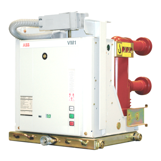
VM1-T
Vacuum circuit breaker
-
For your safety!
That's why our instruction manual begins with these
recommendations:
• Only install switchgear and/or switchboards in
enclosed rooms suitable for electrical equipment.
• Ensure that installation, operation and
maintenance are carried out by specialist
electricians only.
• Comply in full with the legally recognized
standards (DIN VDE/IEC), the connection
conditions of the local electrical utility and the
applicable safety at work regulations.
• Observe the relevant information in the
instruction manual for all actions involving
switchgear and switchboards.
Pay special attention to the hazard notes in the
instruction manual marked with this warning
symbol.
Danger
Table of contents
and VDE-DIN 40719 Part 2
• Make sure that under operation condition of the
switchgear or switchboard the specified data are
not exceeded.
• Keep the instruction manual accessible to all
persons concerned with installation, operation and
maintenance.
• The user's personnel are to act responsibly in all
matters affecting safety at work and the correct
handling of the switchgear.
• Always observe the five safety rules set out in EN
50110 on establishing and securing the off-circuit
condition at the place of work for the duration of
work on the switchgear.
- Isolate
- Secure to prevent reconnection
- Check the off-circuit condition
- Earth and short-circuit
- Cover the guard off adjacent live parts
If you have any further questions on this instruction
manual, the members of our field organization will be
pleased to provide the required information.
3
4
6
9
10
11
14
20
21
30
42
Advertisement
Table of Contents

Related Manuals for ABB VM1-T


Summary of Contents for ABB VM1-T
-
Page 1: Table Of Contents
— MEDIUM VOLTAGE PRODUCTS VM1-T Vacuum circuit breaker Table of contents 1. Summary 2. Structure 3. Function 4. Despatch and storage 5. Installation and mounting of the breaker 6. Commissioning / Operation 7. Maintenance 8. Application of the X-ray regulations 9. - Page 2 10.1 Technical data, general maloperation (for C.B. on 10.1.1 Technical data Control electronics 10.1.2 Technical data AC/DC converter withdrawable part) 3.4.2 Interlocks for VM1-T withdrawable 10.1.3 Permissible number of vacuum parts interrupter operating cycles 10.2 Technical data 3.4.3 Interlocks when non-original...
-
Page 3: Summary
- the average value of the water vapour pressure, The vacuum circuit breakers of type VM1-T in column over a period of 24 h, does not exceed 2.2 kPa design can be supplied both as individual units for - the average value of the relative humidity, over a stationary mounting and mounted on trucks. -
Page 4: Structure
V M 1 -T - VACUUM CIRCUIT BREAKER — Structure 2.1.2 Storage capacitor Structure of the operating (Figures 9/13, 9/15b and 9/25) mechanism (Figures 9/10 to The electrical energy for operation of the circuit breaker is stored in three capacitors. The capacitors 9/13 and 9/25) are designed in such a way that the energy for an The operating mechanism is of the magnetic type. - Page 5 M E D I U M V O LTA G E P R O D U C T S Structure of the breaker poles Basic structure of the circuit (Figures 9/6, 9/7 and 9/11) breaker on withdrawable part (Figures 9/5 to 9/9 and 9/21) The poles in column design are mounted on the bracketshaped rear part of mechanism enclosure 1.
-
Page 6: Function
V M 1 -T - VACUUM CIRCUIT BREAKER — Function 3.1.4 Circuit breaker controller Function of the circuit breaker All the conditions for control of the opening and operating mechanism closing commands to the magnetic actuator are defined in a fixedprogrammed logic module: • Supply voltage must be applied to the AC/DC 3.1.1 Magnetic actuator... - Page 7 3.1.6 Blocking magnet -RL2 If no voltage is applied to -MU, the VM1-T cannot be closed normally. However a closing support function (Figure 9/27) is provided, that can enable the closing operation The optional blocking magnet prevents the even if no voltage is applied to -MU.
- Page 8 10 to 10 hPa, only a relatively small 1. The VM1-T can only be closed via input -MC when contact gap is required to achieve a high dielectric a voltage of 24 V to 240 V AC/DC is applied to strength.
-
Page 9: Despatch And Storage
M E D I U M V O LTA G E P R O D U C T S — Despatch and storage Condition on delivery 4.4 Delivery • The factory-assembled switching devices are The duties of the consignee on receipt of the checked at the works for completeness of the switching devices at site include the following: equipment installed and simultaneously... -
Page 10: Installation And Mounting Of The Breaker
V M 1 -T - VACUUM CIRCUIT BREAKER — Installation and mounting of the breaker Careful and professional installation of the Recommended switchgear is one of the fundamental conditions of tightening torque ( trouble-free circuit breaker operation. Lubricant ( • Install the mechanism enclosure in the panel Thread without (dry) Oil or grease... -
Page 11: Commissioning / Operation
1.2. • For this reason, an internal circuit applies a • Before a VM1-T on the withdrawable part is moved voltage of 80 V to the input -RL1 (Figure 9/15b), as it must be verified that the circuit breaker is soon as the storage capacitor is charged in as- switched off. - Page 12 V M 1 -T - VACUUM CIRCUIT BREAKER — Commissioning / Operation 6.4.2 Manual withdrawal from the service 6.4 Movement of the position into the test/disconnected withdrawable breaker part position • Ensure that the circuit breaker is in the OFF (Figures 9/9, 9/16 and 9/20 to position.
- Page 13 M E D I U M V O LTA G E P R O D U C T S 6.4.4 Withdrawal from the test/disconnected 3. Opening on failure of the supply voltage: position onto the service truck a) Initially, for a period of 180 seconds, opening (Figures 9/21 and 9/22) by remote control or by pressing pushbutton • Open the door of the circuit breaker compartment.
-
Page 14: Maintenance
The vacuum is not even impaired by frequent switching of operating and short-circuit currents. Procedure for capacitor discharge: The typical life expectancy of a VM1-T vacuum circuit 1. Close the circuit breaker. breaker is a function of: 2. Turn off the supply voltage (m.c.b.). - Page 15 • Perform one rapid OFF/ON/OFF operation with • Observe the manufacturer’s instructions and the the circuit breaker to check the storage capacitors special ABB instruction manuals BA 1002/E or BA by pressing buttons 3 and 4 rapidly in sequence. 1006/E on safety at work.
- Page 16 - Fit the contact system back to front on the thin • Open the VM1-T circuit breaker. end of arbor 39, and slide it forwards onto the • Earth all poles of the VM1-T circuit breaker on one thicker part of the shank. side.
- Page 17 - Replacement of the circuit breaker control set. module may only be performed by ABB after- In test operations, the withdrawable part must be sales service personnel or by specially trained moved by hand with the crank fitted with the motor specialists.
- Page 18 Withdrawable assembly of VM1-T: on motor-operated withdrawable parts must not be capable of being switched on. • Manually movable withdrawable assembly: 3.
- Page 19 GCE0007706P0100 ABB Instruction manual BA 1006/E GCEA901006P0101 Paint: Touch-up paint: Standard colour RAL 7035 - 1-kg-box GCE9014060R0103 - Spray tin GCE0007895P0100 Table: VM1-T withdrawable part Designation Item Rated supply Part no. voltage (order code) Auxiliary switch for manually operated mechanism -BT2 / -BT1 - Silver-plated contacts...
-
Page 20: Application Of The X-Ray Regulations
V M 1 -T - VACUUM CIRCUIT BREAKER — Application of the X-ray regulations One of the physical properties of vacuum insulation The results are as follows: is the possibility of X-ray emissions when the • Testing of the switching device or the vacuum contact gap is open. -
Page 21: Figures
M E D I U M V O LTA G E P R O D U C T S — Figures Figure 9/1: Vacuum circuit breaker, type VM1-T, for fixed installation, Figure 9/2: Vacuum circuit breaker, type VM1-T, for fixed installation, 12 kV, ≤ 1250 A, ≤ 25 kA, mechanism side. - Page 22 V M 1 -T - VACUUM CIRCUIT BREAKER — Figures 36.1 34.1 Figure 9/7: Vacuum circuit breaker, type VM1-T, on withdrawable part, Figure 9/8: Vacuum circuit breaker, type VM1-T, on withdrawable part, 24 kV, 1250 A, ≤ 25 kA, pole side. 24 kV, 1250 A, ≤ 25 kA, mechanism side. Breaker pole Withdrawable assembly Contact arm with insulating tube (versions for rated 36.1 Control wiring plug...
- Page 23 Figure 9/12: Position indicator. Mechanical position indicator Sensor -B0A for “circuit breaker OFF” signal Sensor -B0E for “circuit breaker ON” signal Figure 9/11: Sectional view of a vacuum circuit breaker type VM1-T, schematic diagram. Mechanism enclosure Lever shaft Front plate, removable...
- Page 24 V M 1 -T - VACUUM CIRCUIT BREAKER — Figures External circuit breaker connection: Inputs: Switching command OFF (closed circuit) -RL1 Closing lock-out (closed circuit) -RL1 -MO2 Switching command OFF 2 (open circuit) LOGIC -MO1 Switching command OFF 1 (open circuit) -MO2 Switching command ON (open circuit) Supply voltage...
- Page 25 -DO1 I 1002 Closing support for -MU If the DIP-switch is in ON position, the On Off VM1-T with activated undervoltage release -MU can be closed even if no voltage is applied to -MU. For VM1-T: OFF On Off Always ON (enables -MO2) in spite of failure...
- Page 26 V M 1 -T - VACUUM CIRCUIT BREAKER — Figures Circuit breaker controller Circuit breaker Inputs: Supply voltage Switching command (OFF) (closed circuit) -RL1 Closing lock-out (closed circuit) -MO2 Switching command OFF 2 (open circuit) -MO1 Switching command OFF 1 (open circuit) Switching command ON (open circuit) Outputs: -BB4...
- Page 27 Emergency manual opening lever Spring to secure the opening capacity 35.2 Figure 9/18: Emergency manual switch-off of a VM1-T circuit breaker Figure 9/20: Moving the circuit breaker on a withdrawable part between with panel door closed, example. the test/disconnected position and the service position;...
- Page 28 - Service truck engaged with the panel truck atch to engage. - Move the sliding handles inwards to disengage 40.1 Height adjuster for the load surface Withdrawable part with VM1-T circuit breaker 40.2 Guide pin 35.3 Sliding handle 40.3 Catch Service truck 39.1...
- Page 29 41.2 41.1 41.5 Locked 15 16 27.1 Figure 9/25: View of the operating mechanism of the VM1-T circuit breaker with auxiliary devices, front plate removed. Mechanical operating cycle counter Mechanical position indicator Receptacle for emergency manual opening lever 41.4 35.5 Magnetic actuator Sensor for “circuit breaker OFF“...
-
Page 30: 10. Technical Data
• Protection of power feed (must be ordered): according to the type of filter card 1): - Power pack A: - 24 V … 60 V ABB-Stotz m.c.b.: S 282 UC-K; 1.6 A –15% +15% 24 V … 60 V - Power pack B: –30%... - Page 31 M E D I U M V O LTA G E P R O D U C T S 10.1.3 Permissible number of vacuum interrupter operating cycles 10 5 10 3 10 2 0,01 0,02 0,03 0,05 0,08 0,2 0,3 0,4 0,5 0,6 0,8 4 5 6 7 8 10 Breaking curr e nt l (kA)
- Page 32 V M 1 -T - VACUUM CIRCUIT BREAKER — 10. Technical data 10 5 10 5 10 3 10 3 10 2 10 2 0,01 0,02 0,03 0,05 0,08 0,2 0,3 0,4 0,5 0,6 0,8 4 5 6 7 8 10 0,01 0,02 0,03 0,05...
- Page 33 Breaker Rated Rated Rated short- Pole Weight ( Permissible of type voltage current circuit breaking centres vacuum-interrupter current symm. ( switching operations VM1-T approx. kg Figure 9/28 page 32 1212-20 1250 90/95 Diagram B 1220-20 2000 210/275 135/140 Diagram C 1212-25 1250 210...
- Page 34 M = Minimum clearance to DIN VDE 0101 = PE conductor terminal, use contact washer Rated Rated Rated voltage current short-circuit breaking current 150 450 395 400 450 12 / 17.5 630 / 1250 ... 25 210 570 515 520 570 Figure 10/1: Dimensional drawing of circuit breaker type VM1-T: - 12 / 17.5 kV, 630 A und 1250 A, … 25 kA...
- Page 35 1600 / 2000 ... 25 210 610 555 560 600 275 750 695 700 750 17.5 1600 / 2000 ... 25 210 610 555 560 600 275 750 695 700 750 Figure 10/2: Dimensional drawing of circuit breaker type VM1-T: - 12 kV, 1600 … 2000 A, … 25 kA - 17.5 kV, 1600 … 2000 A, … 25 kA...
- Page 36 M = Minimum clearance to DIN VDE 0101 = PE conductor terminal, use contact washer Rated Rated Rated voltage current short-circuit breaking current 630 / 1250 ... 25 210 570 515 520 570 275 750 695 700 750 Figure 10/3: Dimensional drawing of circuit breaker type VM1-T: - 24 kV, 630 A and 1250 A, … 25 kA...
- Page 37 ( current operations symm. ( (peak) ( approx. Figure 9/28 VM1-T page 31/32 1212-16 1250 Diagram A 1212-20 1250 Diagram B 1216-20 1600 210 135/140 Diagram C 1206-25 630 27.3 Diagram D...
- Page 38 503 127 UniGear type ZS1 1250 A, ... 25 kA 1250 A, ... 25 kA 150 502 466 490 503 Table 2: UniGear type ZS1 150 624±2 618 628 620±2 128±1 120±1 30±1 203±1 Figure 10/4: Vacuum circuit breaker on withdrawable part, type VM1-T: - Use in UniGear type ZS1 - 12 kV, … 1250 A, … 25 kA - 17.5 kV, … 1250 A, … 25 kA...
- Page 39 2000 A, … 25 kA 2000 A, ... 25 kA 210 650 618 640 653 2000 A, … 25 kA 2000 A, ... 25 kA Table 2: 210 691±2 688 698 688±2 111±1 273±2 UniGear type ZS1 691±2 688±2 111±1 273±2 Figure 10/5: Vacuum circuit breaker on withdrawable part, type VM1-T: - Use in UniGear type ZS1 - 12 kV, 1600 … 2000 A, … 25 kA - 17.5 kV, 1600 … 2000 A, … 25 kA...
- Page 40 -RL2 and is therefore not isolated. Figure 10/7: Wiring diagramm for VM1-T vacuum circuit breaker on manually movable withdrawable assembly: - Maximal of equipment...
- Page 41 ) Connection exists when auxiliary switches -BB1 and -BB3 are not used. See page 42 for comparison of IEC/VDE designations. Figure 10/8: Wiring diagram for VM1-T vacuum circuit breaker on motor-driven withdrawable assembly: - Maximum of equipment - Control wiring plug 58-pole...
-
Page 42: Comparison Of Designations To Iec 61346-1 / 61346-2, Iec 81346-1 / 81346-2
V M 1 -T - VACUUM CIRCUIT BREAKER — 11. Comparison of designations to IEC 61346-1 / 61346-2, IEC 81346-1 / 81346-2 and VDE-DIN 40719 Part 2 Description IEC 61346-1 / 61346-2 IEC 81346-1 / 81346-2 VDE DIN 40719 Part 2 Blocking magnet for withdrawable part with rectifier -TR5 -RL2 -RLE2 Closing lock-out (closed circuit) -RL1 -RLE1 Switching command OFF 1 (open circuit) -MO1 -MBO1... - Page 43 M E D I U M V O LTA G E P R O D U C T S...
- Page 44 GERMANY GERMANY Tel.: 02102 12-0 Fax: 02102 12-17 77 E-Mail: powertech@de.abb.com www.abb.com/mediumvoltage The data and illustrations are not binding. We reserve the right to modify the contents of this document following technical developments. © Copyright 2022 ABB. All rights reserved.