
Related Manuals for Intracom ULTRALiNK-FX80


Summary of Contents for Intracom ULTRALiNK-FX80
- Page 1 Native Packet Microwave Native Packet Microwave Solution Solution 5 5 7 7 / / 3 3 0 0 0 0 - - C C D D G G Installati Installation & Cabling & Cabling Manual Manual Edition 1.0 Edition 1.0 Confidential Confidential...
- Page 3 INTRACOM S.A. TELECOM SOLUTIONS and/or their respective owners. are owned by INTRACOM S.A. TELECOM SOLUTIONS and/or their respective owners. This document is made available to the end users only for their internal use.
-
Page 4: Table Of Contents
UltraLink-FX80 UltraLink-FX80 Installation & Cabling Manual - Edition 1.0 Installation & Cabling Manual - Edition 1.0 Table of Contents Table of Contents 1. 1. Introd Introductio uction n .................................................. 1 1 About this Docume About this Document nt .. - Page 5 Table of Contents (Page intentionally left blank) -II-...
- Page 6 UltraLink-FX80 Installation & Cabling Manual - Edition 1.0 Equipment Disposal Disposal of old electrical and electronic equipment (applicable through the European Union and other European countries with separate waste collection systems). This symbol, found on this product and any of its parts or on its operating instructions or on its packaging, indicates that electrical and electronic equipment may not be disposed of as unsorted municipal waste.
- Page 7 Table of Contents Declaration of Conformity Hereby, Intracom S.A. Telecom Solutions declares that the product UltraLink is in compliance with the essential requirements and other relevant provisions of the directive 1999/5/EC, and with the requirements of the RoHS directive 2011/65/EU.
-
Page 8: Introd Introductio Uction
UltraLink-FX80 Installation & Cabling Manual - Edition 1.0 1. Introduction About this Document Scope of This document is the Installation & Cabling Manual of the UltraLink -FX80 document equipment: Target This document is addressed to certified technicians with wireless equipment... -
Page 9: Safety Y Preca Safet Precautio Utions
Chapter 1 Introduction Safety Precautions GENERAL • Only trained, authorized personnel should have access to the installed equipment. • The equipment premises should be of restricted access. • Appropriate labeling should exist at points with high risk of contact with hazardous voltage. -
Page 10: Data Data And And Direct Direct Powering Powering
UltraLink-FX80 Installation & Cabling Manual - Edition 1.0 Safety Precautions , Continued GROUNDING Never power on any equipment (except indoor AC PoE) unless you have completed the grounding installation as described in this manual. There is risk of equipment failure and / or electrical shock. - Page 11 Chapter 1 Introduction Safety Precautions , Continued AC or DC Power PROPER SWITCHING ON / OFF Never connect or disconnect the power cable to or from the radio unit as well as the power injector when the local power supply sources (AC or DC) is There is risk of equipment failure.
-
Page 12: Equip Equipment Ment Mater Materials Ials
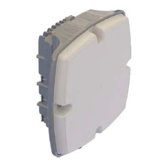
UltraLink-FX80 Installation & Cabling Manual - Edition 1.0 2. Equipment Materials Radio Unit Introduction The following packing lists are available: • Models with a flat antenna included in the package. Models with no antenna included in the package. • Continued on next page... - Page 13 Chapter 2 Equipment Materials Chapter 2 Equipment Materials Radio Unit Radio Unit , , Continued Continued Models Models The available models are shown in the table below: The available models are shown in the table below: with with antenna antenna Order Order Code...
- Page 14 UltraLink-FX80 UltraLink-FX80 Installation & Cabling Manual - Edition 1.0 Installation & Cabling Manual - Edition 1.0 Radio dio Unit Unit , , Continued Continued Models Models The available models are shown in the table below: The available models are shown in the table below:...
- Page 15 Chapter 2 Equipment Materials Chapter 2 Equipment Materials Radio Unit Radio Unit , , Continued Continued Packing list, Packing list, continued continued UltraLink UltraLink – FX80 radio unit label: – FX80 radio unit label: Item Item Description Description Where: Where: X X is is E: E: for embedded flat antenna or...
-
Page 16: Antennas
UltraLink-FX80 Installation & Cabling Manual - Edition 1.0 Antennas Flat Order Code Description ANT-7080-FL1 Flat antenna (mounting kit included). Packing list: Item Description Flat antenna (with plastic cover). Mounting kit (for a pole of 48 mm to 100 mm diameter). - Page 17 Chapter 2 Equipment Materials Antennas , Continued Parabolic The following list shows the available parabolic antennas: Item Order Code / Photo Description Parabolic antenna of 38 cm diameter ANT-7080-30P (mounting kit included). A Parabolic antenna of 65 cm diameter (mounting kit included). ANT-7080-60P Mounting kit includes mounting bracket and adaptation plate to mount the UltraLink -FX80 radio unit...
-
Page 18: Power Supply Materials
UltraLink-FX80 Installation & Cabling Manual - Edition 1.0 Power Supply Materials Topics This paragraph includes the following topics: Topic See Page Power injectors models Power injectors Power cables Power modules Power connectors Continued on next page... - Page 19 60 W Other types of PoE injectors may be offered based on specific customer needs. Third party PoE injectors need prior interoperability confirmation by Intracom Telecom. UltraLink -FX80 radio can be powered by PoE / PonE only when fitted with the DC power module option.
- Page 20 UltraLink-FX80 Installation & Cabling Manual - Edition 1.0 Power Supply Materials , Continued Power injectors The following table shows the power injectors materials in details: Item Order Code / Photo Description Indoor power injector POE-ID-AC75 ° C to +40 °...
- Page 21 Chapter 2 Equipment Materials Power Supply Materials , Continued Power cables The following table shows the power cables: Item Order Code / Photo Description A AC-PWR-CAB AC power bulk cable, 3 x 0.75 mm , 0.6 / 1 kV, stranded, UV-rated, industrial type, for outdoor use (per meter) (when distance from the local AC power supply source <...
- Page 22 UltraLink-FX80 Installation & Cabling Manual - Edition 1.0 Power Supply Materials , Continued Power modules The UltraLink -FX80 radio unit is provided by the manufacturer with an AC or a DC power module pre-installed on it. However, the power modules can be ordered separately and installed on the...
-
Page 23: Groun Groundin Ding G
Chapter 2 Equipment Materials Grounding Introduction Grounding cables for indoor and outdoor installation are available depending on the installation premises requirements. In each case, two wire gauges are available: 16mm cable is used for units installed on structures where lightning strike •... -
Page 24: Lightning & Surge Protectors
UltraLink-FX80 Installation & Cabling Manual - Edition 1.0 Lightning & Surge Protectors The lightning & surge protector (LSP) should be ordered when lightning surge protection is deemed necessary (recommended) and installed close to the following equipment: • Radio unit. •... -
Page 25: Data Data Traffi Traffic C Mate Material
Chapter 2 Equipment Materials Data Traffic Material Topics This paragraph includes the following topics: Topic See Page Bulk cables & accessories Kits Fiber optic cables SFPs & Glands Continued on next page... - Page 26 UltraLink-FX80 Installation & Cabling Manual - Edition 1.0 Data Traffic Material , Continued Bulk cables & The following table shows the S-FTP cables, accessories and kits: accessories The total length of S-FTP cable from the radio unit up t o the local equipment must not exceed 100 m.
- Page 27 Chapter 2 Equipment Materials Data Traffic Material , Continued Fiber optic The following table shows the fiber optic cables: cables Order Code Description FBROPTMM-025 25 m FBROPTMM-50 50 m Prefabricated, FBROPTMM-100 100 m connectorized fiber optic cables FBROPTMM-150 150 m for outdoor use, DX, 2 x LC / PC FBROPTMM-200...
- Page 28 UltraLink-FX80 Installation & Cabling Manual - Edition 1.0 Data Traffic Material , Continued SFPs & Glands The following table shows the SFPs and glands: Optical SFPs Order Code Description SFP, Multi-Mode, SFP-MM-500M up to 500 m, 1.25 Gbit/s, 850 nm.
-
Page 29: Pole Fastening Material
Chapter 2 Equipment Materials Chapter 2 Equipment Materials Pole Fastening Material Pole Fastening Material Mounting Mounting Order Order Code Code Description Description bracket bracket Mounting bracket and Mounting bracket and accessories for accessories for installation of installation of INST-PONE-PL INST-PONE-PL PONE-OD-DC PONE-OD-DC power power... -
Page 30: Alignment Ma Alignment Materials Terials
UltraLink-FX80 UltraLink-FX80 Installation & Cabling Manual - Edition 1.0 Installation & Cabling Manual - Edition 1.0 Alignment Materials Alignment Materials Alignment tool Alignment tool Order Order Code Code Description Description Universal alignment Universal alignment tool kit (reusable) for tool kit (reusable) for... -
Page 31: Equipment Connections
Chapter 3 Equipment Connections Chapter 3 Equipment Connections 3. Equipment Connections 3. Equipment Connections UL-FX 80 UL-FX 80 The following picture shows the UltraLink The following picture shows the UltraLink –FX80 interface rec –FX80 interface receptacles that eptacles that connection connection appear when removing their respective plastic covers: appear when removing their respective plastic covers:... - Page 32 UltraLink-FX80 Installation & Cabling Manual - Edition 1.0 Equipment Connections , Continued Outdoor DC The following picture shows the PonE injector interface receptacles that PonE appear when removing the cover plate: PonE injector receptacles are described below: Marking Details A...
- Page 33 Chapter 3 Equipment Connections Equipment Connections , Continued Outdoor AC The following picture shows the outdoor AC PonE interfaces receptacles: PonE PonE injector receptacles are described below: Marking Details A GbE IN / Ethernet • OUT: Connection of the Gigabit GbE OUT 100/1000Base-T, Ethernet S-FTP cable carrying electrical (RJ-45 with...
- Page 34 UltraLink-FX80 Installation & Cabling Manual - Edition 1.0 Equipment Connections , Continued Indoor AC PoE The following picture shows the PoE interface receptacles: PoE injector receptacles are described below: Marking Details A GbE IN / Ethernet • OUT: Connection of the Gigabit...
-
Page 35: Recommended Tools
Chapter 4 Recommended Tools 4. Recommended Tools Introduction The following list of tools is installer responsibility to be supplied during installation. Equipment Item Tool/ Photo Description installation Adjustable torque wrench tools with socket for : • M8 screws 13 mm •... - Page 36 UltraLink-FX80 Installation & Cabling Manual - Edition 1.0 Recommended Tools , Continued Ethernet cable Item Tool/ Photo Description termination Pliers (long nose). tools Crimping tool for terminating S-FTP cable to RJ-45 jacks (for connector with order code ST-45). Ethernet cable tester.
- Page 37 Chapter 4 Recommended Tools Recommended Tools , Continued Grounding Item Tool/ Photo Description cable Crimping tool for ring terminals termination (16 mm and 6 mm tools Hot Air Gun.
-
Page 38: Installation Prerequisites
UltraLink-FX80 Installation & Cabling Manual - Edition 1.0 5. Installation Prerequisites Introduction This section describes all the prerequisites that must be considered prior to installing the equipment. Site Survey Site survey should be done before start the installation taking in... - Page 39 This can also provide partial protection against Lightning-induced current. For additional protection against lightning LSPs need to be used. For more information regarding the installation of LSP/PSP please refer to the following manual: Lightning & Surge Protection for Intracom Telecom Radios – Installation Practices Continued on next page...
- Page 40 UltraLink-FX80 Installation & Cabling Manual - Edition 1.0 Installation Prerequisites , Continued Wall All power injectors offered by Intracom Telecom can be installed as desktop installation or on a wall surface, as shown below: • Indoor AC PoE: Materials for wall mount installation are not included on the packing list of the product ((requires wood plugs (5 mm X 25 mm) and wood screws cross-headed (4 mm x 30 mm)).
- Page 41 Chapter 5 Installation Prerequisites Installation Prerequisites, Continued , Continued Pole • The pole construction should be rust free and strong enough. installation • Should be perfectly perpendicular to allow correct alignment of the antenna. • The UltraLink –FX80 installation onto the pole (for flat antenna) requires 1 meter available space.
- Page 42 For more information regarding the installation of LSP/PSP please refer to the following manual: Lightning & Surge Protection for Intracom Telecom Radios – Installation Practices Power input For applicable input voltage ranges please refer to Power Supply Materials voltage on page 11.
-
Page 43: Cabl Cabling Ing Over Overvie View W
Chapter 6 Cabling Overview 6. Cabling Overview Introduction Three types of cables can be connected to UltraLink -FX80 interfaces as follows: • Gigabit Ethernet (S-FTP) Cable (Cat 5E or Cat 6) • Fiber Optic Cable (Single mode or Multimode) • Power Supply Cable (AC or DC). - Page 44 UltraLink-FX80 Installation & Cabling Manual - Edition 1.0 Cabling Overview , Continued Cable length A): Maximu m l ength of cables us ed f or Data Traff ic : restrictions Given that the maximum line rate of each traffic interface supported by UltraLink - FX80 is 1Gbps Ethernet and depending on the type of cable...
- Page 45 Chapter 6 Cabling Overview Cabling Overview, Continued Cable length • Direct AC powering cables: restrictions The maximum cable length of the recommended 3 x 0.75 mm cable is 300 ,continued meters. • S-FTP cable (CAT5E or CAT6) used with provided power injectors −...
- Page 46 UltraLink-FX80 Installation & Cabling Manual - Edition 1.0 Data and Direct Powering Data and direct The following schematic shows a cabling overview when the powering is powering (AC direct (AC or DC): or DC) Continued on next page...
-
Page 47: Data And External Powering (Power Injector)
Chapter 6 Cabling Overview Data and External Powering (Power Injector) Data and outdoor DC PonE The following schematic shows a cabling overview when powering is through an external power injector (outdoor DC PonE): UltraLink -FX80 radio can be powered by PoE / PonE only when fitted with the DC power module. - Page 48 UltraLink-FX80 Installation & Cabling Manual - Edition 1.0 Data and External Powering (Power Injector) , Continued Data and outdoor AC PonE The following schematic shows a cabling overview when powering is through an external power injector (outdoor AC PonE): UltraLink -FX80 radio can be powered by PoE / PonE only when fitted with the DC power module.
- Page 49 Chapter 6 Cabling Overview Data and External Powering (Power Injector) , Continued Data and indoor AC PonE The following schematic shows a cabling overview when powering is through an external power injector (indoor AC PonE): UltraLink -FX80 radio can be powered by PoE / PonE only when fitted with the DC power module.
-
Page 50: Installation
UltraLink-FX80 Installation & Cabling Manual - Edition 1.0 7. Installation & Cabling (UltraLink – FX80) Overview Introduction The UltraLink - FX80 radio unit can be combined with flat or parabolic antenna. This chapter describes the installation & cabling of the UltraLink -FX80 radio unit with flat antenna. -
Page 51: Installing Grounding Cable
Chapter 7 Installation & Cabling (UltraLink – FX80) Installing Grounding Cable Apply this procedure for grounding the UltraLink –FX80 radio unit. Introduction Tools and Description materials Materials • Grounding kit for radio unit on page 16 Tools • Item 1 (with socket for M5 screw ) from Equipment installation tools on page 28 •... - Page 52 UltraLink-FX80 Installation & Cabling Manual - Edition 1.0 Installing Grounding Cable , Continued Procedure To install grounding cable to radio unit, proceed as follows: Step Action Prepare and terminate the grounding cable as instructed in Appendix C: Terminating Grounding Cable on page 77.
-
Page 53: Installing Mounting Kit For Installing Mountin G Kit For Ultralink - Fx80 With Flat Antenna Ultralink - Fx80 With Flat Antenna
Chapter 7 Installation & Cabling (UltraLink – FX80) Installing Mounting Kit for UltraLink - FX80 with Flat Antenna Apply this procedure for installing the mounting kit of the UltraLink – FX80 Introduction with flat antenna. Antenna space prerequisites Mechanical Adjustment Range & Space requirements The following pictures show the for antenna alignment in both axes (azimuth &... - Page 54 UltraLink-FX80 Installation & Cabling Manual - Edition 1.0 Installing Mount ing K it for UltraLink - FX80 with Flat Antenna , Continued Tools and Description materials Materials Item 3 from Models with antenna on page 6 Tools Item 1 (both sockets) from Equipment installation tools on page 28 ...
- Page 55 Chapter 7 Installation & Cabling (UltraLink – FX80) Installing Mounting Kit for UltraLink - FX80 w ith Flat Antenna , Continued Procedure, continued Step Action As soon as the pole bracket has been fixed to the pole, proceed as follows: •...
- Page 56 UltraLink-FX80 Installation & Cabling Manual - Edition 1.0 Installing Mounting Kit for UltraLink - FX80 w ith Flat Antenna , Continued Procedure, continued Step Action Use the tool item 1, to tighten the M5 & M8 screws. Do not over tighten. Adjust the tool for tightening of M5 and M8 screws respectively (maximum tightening torque 4.2...
- Page 57 Chapter 7 Installation & Cabling (UltraLink – FX80) Installing UltraLink - FX80 with Flat Antenna onto Mounting Tools and Description materials Materials • UltraLink -FX80 radio unit with flat antenna Tools • Item 1 (with M5 socket) from Equipment installation tools on page Continued on next page...
- Page 58 UltraLink-FX80 Installation & Cabling Manual - Edition 1.0 Installing UltraLink - FX80 with Flat Antenna onto Mounting , Continued Procedure To install the UltraLink -FX80 with flat antenna onto mounting kit, proceed as follows: Step Action Using the tool item 1 (with socket for M5 screw), proceed as follows: a.
- Page 59 Chapter 7 Installation & Cabling (UltraLink – FX80) Installing UltraLink - FX80 with Flat Antenna onto Mounting , Continued Procedure, continued Step Action Install the safety screw as shown below: Use the tool item 1, to tighten the M5 screws. Do not over tighten.
-
Page 60: Installing Installing Ultralink Ultralink - Fx80 - Fx80 Cables Cables
UltraLink-FX80 Installation & Cabling Manual - Edition 1.0 Installing UltraLink – FX80 Cables Topics This paragraph includes the following topics: Topic See Page S-FTP cable installation SFP and cable installation Power supply cable installation Only outdoor Cat 5E or Cat6 S-FTP cables should be used in UltraLink FX80 installations. - Page 61 Chapter 7 Installation & Cabling (UltraLink – FX80) Installing UltraLink – FX80 Cables , Continued S-FTP cable To install a Gigabit Ethernet (S-FTP) cable, proceed as follows: installation Step Action Prepare and terminate the Ethernet cable as instructed in Appendix A: Terminating Ethernet (S-FTP) Cable on page 67. Slide all three parts of the supplied gland over the S-FTP cable (UltraLink –...
- Page 62 UltraLink-FX80 Installation & Cabling Manual - Edition 1.0 Installing UltraLink – FX80 Cables , Continued Tools and Description materials Materials • UltraLink -FX80 radio unit with flat antenna Tools • Item 1 (with M5 socket) from Equipment installation tools on page...
- Page 63 Chapter 7 Installation & Cabling (UltraLink – FX80) Installing UltraLink – FX80 Cables , Continued SFP and cable To install an Electrical SFP with S-FTP cable, proceed as follows: installation Step Action Prepare and terminate the Ethernet (S-FTP) cable as instructed in Appendix A: Terminating Ethernet (S-FTP) Cable on page 67.
- Page 64 UltraLink-FX80 Installation & Cabling Manual - Edition 1.0 Installing UltraLink – FX80 Cables , Continued SFP and cable Step Action installation, Press the SFP HOOD flaps to open (A) and then push upwards continued (B) till the HOOD will be locked, as shown below: Insert the last item of the HOOD as shown below (A).
- Page 65 Chapter 7 Installation & Cabling (UltraLink – FX80) Installing UltraLink – FX80 Cables , Continued Precautions Please refer to Safety Precautions on page 2 to the following paragraphs: • AC or DC Power PROPER SWITCHING ON / OFF • LOCAL POWER AC SOURCE and POWER SUPPLY CABLES (AC/DC) Tools and Description materials...
-
Page 66: Installation Of Power Injector (Power Over Ethernet)
UltraLink-FX80 Installation & Cabling Manual - Edition 1.0 8. Installation of Power Injector (Power over Ethernet) Introduction Two types of powering are provided and can be either: • Directly (AC or DC powering) or • Via an external power injector (outdoor DC PonE or outdoor AC PonE or... - Page 67 Chapter 8 Installation of Power Injector (Power over Ethernet) Installation of Power Injector (Power over Ethernet) , Continued Mechanical and For mechanical installation and cabling of outdoor DC PonE, proceed as cabling follows: installation of outdoor DC Step Action PonE For pole installation follow this step.
- Page 68 UltraLink-FX80 Installation & Cabling Manual - Edition 1.0 Installing UltraLink – FX80 Cables , Continued Mechanical and cabling Step Action installation of Install the PonE onto the pole as shown below. outdoor DC PonE, continued Use the flat screwdriver to fully tighten.
- Page 69 Chapter 8 Installation of Power Injector (Power over Ethernet) Installing UltraLink – FX80 Cables , Continued Mechanical and cabling Step Action installation of Prepare and terminate the Ethernet cables as instructed in outdoor DC Appendix A: Terminating Ethernet (S-FTP) Cable on page 67. PonE, continued Use the Torx screwdriver to remove the clamp (A) and then plug the S-FTP cables...
- Page 70 UltraLink-FX80 Installation & Cabling Manual - Edition 1.0 Installing UltraLink – FX80 Cables , Continued Mechanical and cabling Step Action installation of Use the torx screwdriver T10 to screw the clamp (applying outdoor DC maximum tightening torque of 0.9 Nm) for securing the...
- Page 71 Chapter 8 Installation of Power Injector (Power over Ethernet) Installing UltraLink – FX80 Cables , Continued Mechanical and cabling Step Action installation of Prepare and terminate the grounding cable as instructed in outdoor DC Appendix C: Terminating Grounding Cable on page 77. PonE, continued Use the Torx screwdriver T10 to remove the screw and then install the terminal ring.
- Page 72 UltraLink-FX80 Installation & Cabling Manual - Edition 1.0 Installing UltraLink – FX80 Cables , Continued Mechanical and cabling Step Action installation of Install the power supply cable, as follows: outdoor DC PonE, continued Switch-off the Local DC Power Source & the circuit breaker connected between PonE and the Local DC Power Source.
- Page 73 Chapter 8 Installation of Power Injector (Power over Ethernet) Installing UltraLink – FX80 Cables , Continued Mechanical and cabling Step Action installation of This step is related to wall installation only: outdoor DC PonE, continued Use the torx screwdriver T10 to remove the six screws (see below) and detach the PonE cover.
-
Page 74: Appendix A: Terminating Ethernet (S-Ftp) Cable
UltraLink-FX80 Installation & Cabling Manual - Edition 1.0 Appendix A: Terminating Ethernet (S-FTP) Cable Tools and Description materials Materials • Items A, B (for termination type B1/B2) and D (for termination type A1/A2) from Bulk cables & accessories on page 19. - Page 75 Appendix A: Terminating Ethernet (S-FT P) Cable Appendix A: Terminating Ethernet (S-FTP) Cable , Continued Procedure To prepare an Ethernet S-FTP cable with termination type A1/A2, proceed as follows: Step Action For termination type A1: Strip 40 mm of outer jacket. For termination type A2: Strip 80 mm of outer jacket.
- Page 76 UltraLink-FX80 Installation & Cabling Manual - Edition 1.0 Appendix A: Terminating Ethernet (S-FTP) Cable , Continued Procedure, continued Untwist wire pairs and arrange according to the T-568 standard, as shown below: Straight-through cable Continued on next page...
- Page 77 Appendix A: Terminating Ethernet (S-FT P) Cable Appendix A: Terminating Ethernet (S-FTP) Cable , Continued Procedure (continued) Step Action Carefully insert the eight wires into the cavity of the wire guide so that its numbering is visible from the top. Measure 16 mm from the jacket’s end and cut all wires protruding from the guide.
- Page 78 UltraLink-FX80 Installation & Cabling Manual - Edition 1.0 Appendix A: Terminating Ethernet (S-FTP) Cable , Continued Procedure, continued Step Action Fold back the crimping terminal of the connector. Fully insert wire guide and cable into the connector’s body until the shield (overlapping the jacket’s end) reaches the crimping position.
- Page 79 Appendix A: Terminating Ethernet (S-FT P) Cable Appendix A: Terminating Ethernet (S-FTP) Cable , Continued Procedure, continued Step Action Terminate the wires onto the RJ-45 jack. Continued on next page...
- Page 80 UltraLink-FX80 Installation & Cabling Manual - Edition 1.0 Appendix A: Terminating Ethernet (S-FTP) Cable , Continued Procedure (continued) Step Action With the pliers, bring the terminal of the connector back, over the exposed shield, and press gently around the terminal to form. This will achieve good contact with the shield.
- Page 81 Appendix A: Terminating Ethernet (S-FT P) Cable Appendix A: Terminating Ethernet (S-FTP) Cable , Continued Procedure (continued) Step Action With a wire cutter, trim away any braid leftovers extending beyond the end of the plug. When finished, termination should look as below: For termination type A1: For termination type A2: Using the Ethernet tester, test cable for proper wire termination...
-
Page 82: Appendix B: Terminating Power Supply Cable
UltraLink-FX80 Installation & Cabling Manual - Edition 1.0 Appendix B: Terminating Power Supply Cable Tools and Description materials Materials • Items A or C from Power cables on page 14 • Items A or B from Power modules on page 15 •... - Page 83 Appendix B: Terminating Power Supply Cable Installing UltraLink – FX80 Cables , Continued Procedure To terminate the power supply cable (AC or DC) to the respective connector of UltraLink -FX80, proceed as follows: Step Action Strip approx. 10 mm from the cable’s outer sheath. Pass the connector parts 1, 2 and 3 over the cable’s end, as shown below: 4 mm...
-
Page 84: Appendix C: Terminating Grounding Cable
UltraLink-FX80 Installation & Cabling Manual - Edition 1.0 Appendix C: Terminating Grounding Cable Topics This paragraph includes the following topics: Topic See Page Grounding cable termination procedure for Radio Units grounding Procedure for DC PonE cable Tools and Description materials Materials •... - Page 85 Appendix C: Terminating Grounding Cable Installing UltraLink – FX80 Cables , Continued How to terminate the grounding cable of radio unit, proceed as follows: Procedure for radio units cable Step Action grounding Cut the grounding cable according to the distance between radio unit and local grounding bar.
- Page 86 UltraLink-FX80 Installation & Cabling Manual - Edition 1.0 Installing UltraLink – FX80 Cables , Continued How to terminate the grounding cable of PonE device, proceed as follows: Procedure for DC PonE cable grounding Step Action Cut the grounding cable according to the distance between PonE and local grounding bar.
-
Page 87: Appendix D: Installing Mounting Kit Alignment Accessories
Appendix D: Installing Mounting Kit Alignment Accessories Appendix D: Installing Mounting Kit Alignment Accessories Overview The following pictures shows an overview of alignment accessories onto mounting kit for antenna alignment: Continued on next page... - Page 88 UltraLink-FX80 Installation & Cabling Manual - Edition 1.0 Appendix D: Installing Mounting Kit Alignment Accessories Continued How to install the tools, proceed as follows: Step Action Install the azimuth tool as shown below: Install the tilt (elevation) tool as shown below:...
-
Page 89: Appendix E: Flat Antenna Polarization Change
Appendix E: Flat Antenna Polarization Change Appendix E: Flat Antenna Polarization Change Precaution Please see the precautions in paragraph Installation procedure overview on page 43. Installation Find below an overview of the flat antenna polarization change procedure of procedure the UltraLink –FX80 with flat antenna: overview Steps... - Page 90 UltraLink-FX80 Installation & Cabling Manual - Edition 1.0 Appendix E: Flat Antenna Polarization Change , Continued Tools and Description materials Tools Item 5 from Equipment installation tools on page 28 Selecting To select antenna polarization, proceed as follows: antenna polarization...
- Page 91 Appendix E: Flat Antenna Polarization Change Installing UltraLink – FX80 Cables , Continued Selecting antenna Step Action polarization, Mount the adaptation plate onto antenna feeder. Slots position continued should matched as shown below. Then use the cross screw driver to install the adaptation plate onto antenna feeder, as shown below.
- Page 92 UltraLink-FX80 Installation & Cabling Manual - Edition 1.0 Installing UltraLink – FX80 Cables , Continued Selecting antenna Step Action polarization, Install the o-ring (A) and then apply greasing paste (B), as continued shown below: Make sure that the polarization shown as follows: End of Procedure.
- Page 93 Appendix E: Flat Antenna Polarization Change Installi ng UltraLink – FX80 Cables , Continued Tools and Description materials Tools Item 4 ( 1 mm) from Equipment installation tools on page 28 Adjust ing radio To adjust UltraLink – FX80 radio unit polarizer (common with antenna unit polarizer polarization), proceed as follows: Step...
- Page 94 UltraLink-FX80 Installation & Cabling Manual - Edition 1.0 Installing UltraLink – FX80 Cables , Continued Tools and Description materials Tools Item 1 (with socket for M5 screw ) from Equipment installation tools on page 28 Mounting To mount flat antenna onto UltraLink –...
-
Page 95: Appendix E: Receptacles Pin Out
Appendix E: Receptacles Pin Out Appendix E: Receptacles Pin Out UltraLink FX-80 Scope GbE2:For Traffic / Inband / Power GbE1:For Traffic / Inband Type RJ-45 Female (100/1000 Base-T electrical). Pin out Signal Description Transmit and Receive Data A+ Input / Output Transmit and Receive Data A- Input / Output Transmit and Receive Data B+... -
Page 96: Pone Pone
UltraLink-FX80 Installation & Cabling Manual - Edition 1.0 PonE Gbe IN Scope For connection of GbE electrical data traffic. Type RJ-45 Female (10/100/1000 Base-T electrical). Pin out Signal Description Transmit and Receive Data A+ Input / Output Transmit and Receive Data A-... - Page 97 Appendix E: Receptacles Pin Out PonE, Continued INPUT Scope For connection of –48 V dc power supply voltage. Type Three poles power receptacle. Pin out Signal Description Power Supply Return (GND) Input -48 V dc, nominal Input (40 V dc to 60 V dc) Optionally Earth Ground Input...
- Page 98 UltraLink-FX80 Installation & Cabling Manual - Edition 1.0 (Page intentionally left blank)
- Page 99 (Page intentionally left blank)
- Page 100 UltraLink-FX80 Installation & Cabling Manual - Edition 1.0...
Need help?
Do you have a question about the ULTRALiNK-FX80 and is the answer not in the manual?
Questions and answers