
Related Manuals for Minipa ET-1110


Summary of Contents for Minipa ET-1110
- Page 1 MULTÍMETRO DIGITAL DIGITAL MULTIMETER ET-1110 MANUAL DE INSTRUÇÕES INSTRUCTION MANUAL...
-
Page 2: Table Of Contents
ÍNDICE 1. INTRODUÇÃO ........... 02 2. INFORMAÇÕES DE SEGURANÇA ....02 3. ESPECIFICAÇÕES ..........04 3.1 Especificações Gerais ....... 04 3.2 Especificações Elétricas ......05 4. DESCRIÇÃO DO PAINEL FRONTAL ....07 5. OPERAÇÃO ............08 5.1 Medidas de Tensão AC / DC ..... 09 5.2 Medidas de Corrente DC ...... -
Page 3: Introdução
1. INTRODUÇÃO É um instrumento de teste portátil, compacto e operado por bateria. Possui as seguintes características de medida para aplicações principalmente domésticas e de hobistas. - Tensão DC e AC - Corrente DC - Resistência - Temperatura - Teste de Diodo e Continuidade - Data Hold 2. - Page 4 Termos deste Manual CAUTELA Identifica condições ou práticas que podem resultar em danos ao instrumento ou nos equipamentos em teste. ADVERTÊNCIA Identifica condições ou práticas que podem resultar em ferimentos pessoais ou até mesmo a perda da vida. Termos Encontrados no Instrumento ATENÇÃO: Refira-se ao manual.
-
Page 5: Especificações
CAUTELA Para evitar danos ao instrumento: - Desconecte as pontas de prova do circuito em teste antes de mudar de função de medida. - Nunca conecte tensões superiores a 600V DC ou 600V AC RMS. - Nunca conecte tensão aos terminais de entrada quando a chave rotativa estiver selecionada para medir resistência. -
Page 6: Especificações Elétricas
- Uso Interno. - Alimentação: Bateria 9V (NEDA1604, JIS006P). - Dimensões: 138(A) x 72(L) x 38(P)mm. - Peso: Aproximadamente 153g (com bateria). 3.2 Especificações Elétricas Especificações válidas para ciclo de calibração de um ano, temperatura de operação de 18°C a 28°C (64°F a 82°F) e umidade relativa <... - Page 7 Corrente DC FAIXA RESOLUÇÃO PRECISÃO 200µA 0.1µA ±(1.0%+2D) 1µA 20mA 10µA ±(1.5%+2D) 200mA 100µA 10mA ±(3.0%+5D) - Proteção de Sobrecarga: Fusível Ação Rápida 0.25A/ 250V para Entrada mA. Sem Fusível para Entrada 10A (10A máximo por 15s). Resistência FAIXA RESOLUÇÃO PRECISÃO 200Ω...
-
Page 8: Descrição Do Painel Frontal
Diodo - Indicação: Queda de Tensão Direta Aproximada sobre o Diodo. - Tensão de Teste: 3V DC (máximo). - Corrente de Teste: 1.0mA±0.6mA. Continuidade - Indicação: Sonora. - Limiar: Um sinal sonoro é emitido quando a resistência medida estiver abaixo de 30Ω. 4. -
Page 9: Operação
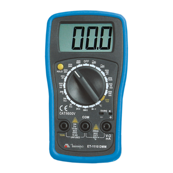
10A DC - Terminal positivo para conexão da ponta de prova vermelha para a medida de corrente en- tre 200mA e 10A. Figura 1 5. OPERAÇÃO ADVERTÊNCIA Leia e entenda completamente este manual de instruções antes de usar o instrumento. -
Page 10: Medidas De Tensão Ac / Dc
O erro de operação ou de desacordo com as instruções e advertências do manual de instruções pode resultar em ferimentos sérios ou até fatais, além de danos materiais. Preparação e Cautela Antes das Medidas 1. Aguarde pelo menos 30 segundos após ter ligado o instrumento antes de efetuar a medida. -
Page 11: Medidas De Corrente Dc
Tome extremo cuidado para evitar o contato com o circuito em teste quando estiver trabalhando com alta tensão. 1. Conecte a ponta de prova preta no terminal de entrada COM e a ponta de prova vermelha no terminal de entrada VΩmA. 2. -
Page 12: Medidas De Resistência
2. Posicione a chave rotativa na faixa de corrente DCA adequada. NOTA: Se a amplitude da corrente a ser medida é desconhecida, comece pela maior faixa e reduza quando necessário. 3. Desligue toda a alimentação do circuito e descarregue todos os capacitores antes de abrir o circuito para conectar o multímetro em série com a carga em teste. -
Page 13: Teste De Diodo
NOTA: Se a resistência a ser medida exceder o valor máximo da faixa, o display mostrará apenas o dígito mais significativo (1). Selecione uma faixa maior. Para valores de resistência de aproximadamente 1MΩ ou maiores, o instrumento pode levar alguns segundos para estabilizar a leitura. -
Page 14: Medidas De Temperatura
da proteção de sobrecarga. Posicione a chave rotativa na faixa 2. Conecte a ponta de prova preta no terminal de entrada COM e a ponta de prova vermelha no terminal de entrada VΩmA. 3. Conecte as pontas de prova no circuito ou dispositivo em teste. -
Page 15: Data Hold
5.7 Data Hold A leitura do display será congelada quando a tecla HOLD for pressionada. Se a tecla for pressionada novamente, a leitura voltará a ser atualizada. 6. MANUTENÇÃO ADVERTÊNCIA Para evitar choque elétrico, remova as pontas de prova do circuito antes de abrir o instrumento. 1. -
Page 16: Troca De Fusível
5. Cuidadosamente levante o gabinete traseiro, separando-o do gabinete frontal. 6. Cuidadosamente retire a bateria, substituindo pela nova. 7. Encaixe o gabinete traseiro no frontal. 8. Recoloque os parafusos. 6.2 Troca de Fusível Refira-se ao seguinte procedimento para examinar ou trocar o fusível do multímetro. 1. -
Page 17: Garantia
5- Caso o instrumento contenha software, a Minipa garante que o software funcionará realmente de acordo com suas especificações funcionais por 90 dias. A Minipa não garante que o software não contenha algum erro, ou de que venha a funcionar sem interrupção. - Page 18 - Correio: Envie uma cópia do certificado de garantia devidamente preenchido pelo correio para o endereço. Minipa Indústria e Comércio Ltda. At: Serviço de Atendimento ao Cliente Alameda dos Tupinás, 33 - Planalto Paulista CEP: 04069-000 - São Paulo - SP - Fax: Envie uma cópia do certificado de garantia...
- Page 19 TABLE OF CONTENTS 1. INTRODUCTION ..........19 2. SAFETY INFORMATION ........19 3. SPECIFICATION ..........21 3.1 General Specification ......... 21 3.2 Electrical Specification ....... 22 4. FRONT PANEL DESCRIPTION ....... 24 5. OPERATION ............25 5.1 AC / DC Voltage Measurement ....26 5.2 DC Current Measurement ......
-
Page 20: Introduction
1. INTRODUCTION It is a portable test instrument, compact and operated by battery. It has the following measurement features for domestic and hobby applications. - DC and AC Voltage - DC Current - Resistance - Temperature - Diode and Continuity Test - Data Hold 2. - Page 21 Terms in this Manual CAUTION It identifies practices or conditions that could result in damage to the instrument or the equipment in test. WARNING It identifies practices or conditions that could result in personal injury or loss of life. Terms in the Instrument ATENTION: Refer to the manual.
-
Page 22: Specification
CAUTION To avoid damages to the instrument: - Remove the test leads from test circuit before changing the measurement function. - Never connect voltages above 600V DC or 600V AC RMS. - Never connect voltage to the input terminals when the rotary switch is selected to measure resistance. -
Page 23: Electrical Specification
- Internal Use. - Power: 9V battery (NEDA1604, JIS006P). - Dimensions: 138(H) x 72(W) x 38(D)mm. - Weight: Approx. 153g (including battery). 3.2 Electrical Specification Accuracy specified to one year calibration period, operation temperature of 18°C to 28°C (64°F to 82°F) and relative humidity <... - Page 24 DC Current RANGE RESOLUTION ACCURACY 200 µ A 0.1 µ A ±(1.0%+2D) 1µA 20mA 10µA ±(1.5%+2D) 200mA 100µA 10mA ±(3.0%+5D) - Overload Protection: Fast Action Fuse 0.25A/250V to mA input. Without fuse to 10A input (10A maximum for 15s). Resistance RANGE RESOLUTION ACCURACY...
-
Page 25: Front Panel Description
Diode - Indication: Approximate Diode Forward Voltage. - Test Voltage: 3V DC (maximum). - Test Current: 1.0mA±0.6mA. Continuity - Indication: Buzzer. - Threshold: A sound signal is emitted, when the measured resistance is under 30Ω. 4. FRONT PANEL DESCRIPTION Refer to Figure 1 to identify controls and terminals. 1. -
Page 26: Operation
Figure 1 5. OPERATION WARNING Read and understand completely this instruction manual before using the instrument. -
Page 27: Ac / Dc Voltage Measurement
Error in operation or in discordance with the warnings and instructions of this manual, can result in material damages and serious or deadly injuries. Preparation and Caution Before Measurement 1. Wait at least 30 seconds after power on the instrument before making measurements. 2. -
Page 28: Dc Current Measurement
Take care to avoid contact with the circuit under test, when working with high voltage. 1. Connect the red test lead to the VΩmA input terminal and the black test lead to the COM input terminal. 2. Set the rotary switch to desired AC ( ) or DC ) range position. -
Page 29: Resistance Measurement
2. Set the rotary switch to desired DCA range position. NOTE: If the current amplitude is unknown, select the highest measurement range, and work down when necessary. 3. Turn off all power from the circuit under test, and discharge all capacitors before opening the circuit to connect the multimeter in series with the circuit. -
Page 30: Diode Test
NOTE: If the measured resistance exceed the maximum value for the selected range, the display will show (1). Select the next range. To measure resistance around 1MΩ or bigger, the instrument can take some seconds to stabilize the reading. It is normal to high resistance readings. -
Page 31: Temperature Measurement
2. Connect the red test lead to the VΩmA input terminal and the black test lead to the COM input terminal. 3. Connect the test leads to the circuit or device under test. Make sure that the power of circuit or device is turned off. -
Page 32: Data Hold
5.7 Data Hold The reading will be hold when the HOLD key is pressed. If the key is pressed once again, it will release the hold and allow a further measurement. 6. MAINTENANCE WARNING To avoid electric shock, remove the test leads from the circuit before opening the multimeter. -
Page 33: Fuse Replacement
5. Carefully separate the front case from the rear case. 6. Carefully remove the old battery replacing for a new one. 7. Replace front case in the rear case. 8. Refasten the screws. 6.2 Fuse Replacement Refer to the following procedure to analyze or replace the fuse. -
Page 34: Warranty
90 days. Minipa will not guarantee that the software will be error free or operate without interruption. Minipa assumes no risk for damage in transit or transportation costs. Warranty will be valid only after the registration of this certificate. - Page 35 The registration can be made by the following ways: - Mail: Send a copy of warranty certificate correctly filled to the following address. Minipa Indústria e Comércio Ltda. Att: Serviço de Atendimento ao Cliente Alameda dos Tupinás, 33 - Planalto Paulista CEP: 04069-000 - São Paulo - SP...
- Page 36 Minipa Eletronics (Shangai) Co. Ltd. Add: 5th, 111 Meisheng Rd. Waigaoqiao Free Trade Zone, Shangai 200137, P.R. China Tel: 86 21 5866 6003 - Fax: 86 21 5866 2054 E-mail: minipa@online.sh.ch Site: www.minipa.net Minipa Indústria e Comércio Ltda. Al. dos Tupinás, 33 - Planalto Paulista - São Paulo - CEP: 04069-000 CGC: 43.743.749/0001-31...
Need help?
Do you have a question about the ET-1110 and is the answer not in the manual?
Questions and answers