
Related Manuals for R2 RINALDI MT

Summary of Contents for R2 RINALDI MT
- Page 1 ENGLISH Mill Grader Mod. MT – MTL – MThi – MTLhi Instructions and maintenance manual (Translation of the original instructions) Rev. 29 – 08 – 2016...
-
Page 3: Table Of Contents
TABLE OF CONTENTS Page WARNING ! …………………………………………………………………………………………... 4 Introduction …………………………………………………………………………………………… 5 Identification of the machine ...……………………………………………………………………... Description of the machine and its appropriate use …………………………………...………… Technical specifications and dimensions …………………………………………………………. Handling and transporting the machine …………………………………………...……………..8 Accident prevention ........................ 10 Components assembly and coupling of the two-wheel tractor …….……………………………... -
Page 4: Warning
Mill grader Mod. MT – MTL – MThi – MTLhi Instructions and maintenance manual (Translation of the original instructions) ----- WARNING ! Read this instruction manual before using the implement Before working on the implement, turn off the two-wheel tractor (or... -
Page 5: Introduction
We would start by thanking you for having chosen our product and hope that you will be happy with your choise. In order that your MILL GRADER Mod. MT – MTL – MThi – MTLhi can offer the maximum efficiency for many years, we ask you to pay attention to the instructions for use and maintenance which you will find in this manual. -
Page 6: Description Of The Machine And Its Appropriate Use
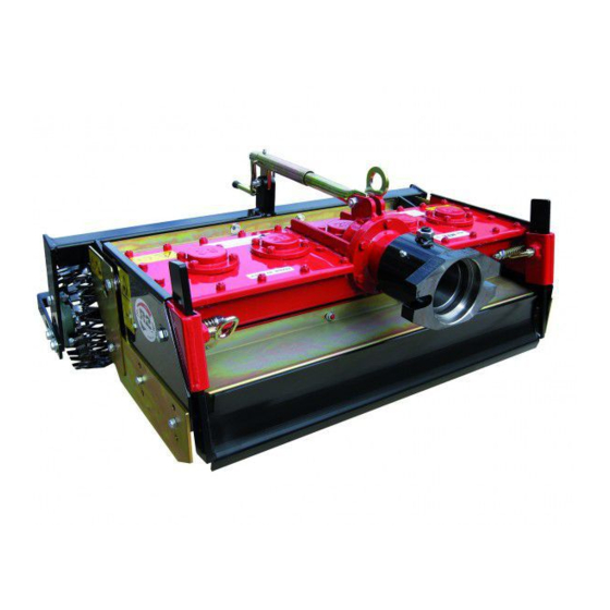
HP, 12-14 HP mills, levels and compresses the soil in a single operation. As it can be seen from the illustration (Fig. 2) the mill grader mod. MT – MTL – MThi – MTLhi is equipped with a central body (power harrow) for the soil refining , of a scraper for the soil levelling and of a special mesh roller to adjust the working depth and the soil compaction .The power harrow mod. - Page 7 Fig. 2 A. Main body of the machine D. Side and side extension. G. Fixed protections. (harrow). E. Scraper. B. Register roller adjustment. F. Walking tractor coupling. C. Roller group. ENGLISH...
-
Page 8: Technical Specifications And Dimensions
3 – Technical specifications and dimensions (*note 2 mod. hi) Model MTL 50 MTL 75 MTL 100 MT 60 MT 90 MT 125 Milling width (Fig. 3a – Ref. A) 50 cm 75 cm 100 cm 60 cm 90 cm 122 cm Levelling width (Fig. - Page 9 Fig. 3a Fig. 3b Fig. 4 Fig. 5 25° ENGLISH...
-
Page 10: Accident Prevention
3. Never approach to the machine moving parts. 4. The mill grader mod. MT – MTL – MThi – MTLhi has been manufactured for a specialized use. It must, therefore, always be in perfect working conditions and only R2 spare parts should be used when making any reparations. - Page 11 Components assembly and coupling of the two-wheel tractor ENGLISH...
-
Page 12: Components Assembly And Coupling Of The Two-Wheel Tractor
6- Components assembly and coupling of the two-wheel tractor (*note 5 mod. hi) Note: all the components that make part of the machine and that must be assembled before using it, have been designed to minimize the user’s work; the parts should be assembled using hand tools (wrenches). - Page 13 Fig. 6 Fig. 7 ENGLISH...
- Page 14 ENGLISH...
- Page 15 Preparation for use Adjustments Machine use Maintenance Replacing the hoes End of work and storage of the implement Scrapping and disposal of components and packaging ENGLISH...
-
Page 16: Preparing For Use
7 – Preparig for use Before using the machine it is necessary to perform the following controls with the two-wheel tractor or tractor off and the key off: 1. Perform a general visual inspection of the implement. Verify the correct mounting of the components (mechanical parts and guards). - Page 17 Fig. 8 Fig. 9 Fig. 10 ENGLISH...
- Page 18 8.3 Procedure for the regulation of the extension sides and the front scraper (check also the part minimum working height from the table technical characteristics page 8): 1. Put the machine on an homogeneous floor; 2. Turn the register roller clockwise; the roller height compared to the floor indicates the working depth while working;...
-
Page 19: Using The Machine
9.2 – Accidental locking of the milling group The MILL GRADER Mod. MT – MTL / MThi – MTLhi has been designed and constructed so as to minimize the possibility that the mill grader can lock while working. -
Page 20: Maintenance
10 - Maintenance (*note 7 mod. hi) During the maintenance operations wear protective gloves; for the lubrification/greasing operations always wear nitrile gloves and protective glasses. If the maintenance is made on a raised plane (for example on a workbench), always wear safety shoes. - Page 21 Fig. 12 Fig. 13 ENGLISH...
-
Page 22: Replacing The Hoes
11 – Replacing the hoes Working the soil determines a gradual consumption of the hoes. When the hoes have become a length of 8 cm, they must be replaced. Using the implement with tools of a length less than 8 cm may cause a reduction of the tillage quality and increase the risk of clamping and damages to the milling group. - Page 23 Fig. 14 Fig. 15 Fig. 16 Fig. 17 A. Hoe support bracket B. Self-locking steel nut M10 fine pitch – DIN C. Nut seat D. Hoe E. Plate F. Steel screw M 10 x 1,25 x 45 fine pitch partial thread DIN 960 – 8.8 Tightening of the hoes screws: 85 Nm 6-7 bar ENGLISH...
-
Page 24: End Of Work And Storage Of The Machine
12 – End of work and storage of the machine If the power harrow mod. MT – MTL / MThi – MTLhi should stay inactive for a long period of time, the following operations must be done: 1. Wash the implement carefully and wipe it dry. -
Page 25: Notes About The Hydraulic Machines
Notes about the hydraulic machines Warranty and Certification ENGLISH... - Page 26 3 – Hydraulic motor (*note 2 mod. hi) Model MTL 50 hi MTL 75 hi MTL 100 hi MT 60 hi MT 90 hi Maximum height from the ground (Fig. 5 – Ref 70 cm 70 cm 70 cm 70 cm...
- Page 27 (*note 3 mod. hi) The power harrows Mthi and MTLhi can be lifted anchoring the lifting equipment to the frame Fig. 18 Ref. 2; pay attention to the machine inclination while lifting it. (*note 4 mod. hi) For the hydraulic machines, it is important to consider the following rules to pevent accidents: Caution: the hydraulic system is under pressure.
- Page 28 (*note 5 mod. hi) In the hydraulic machines the register roller is a screw crank and follow the same steps as those described in the paragraph for the rod register. In this type of machines the tractor connection is supplied by the reseller. Address to the reseller for the assembly connection instructions of the Mill Grader R2-Tractor.
- Page 29 (*note 6 mod. hi) (*note 7 mod. hi) General rules for the hydraulic motor use: Working oil temperatures in the hydraulic system should be kept between +30°C and +60°C. The anti-wear and lubrication properties of the oil are greatly reduced at higer temperatures. The ambient temperature around the engine should be between -30°C and +90°C Only use an oil containing antiwear additives ISO 46 or with a viscosity at normal operating temperature of approx.
-
Page 30: Warranty - Certification
The original text of the operation and maintenance manual has been written in Italian (original instructions). R2 Rinaldi S.r.l. reserves the right to make technical modifications in order to perfect the implement described in this operator’s manual. Claims based on the indications, illustrations and descriptions mentioned herein will not be accepted The R2 Rinaldi S.r.l. - Page 32 R2 Rinaldi S.r.l. Via degli Artigiani, 23 40024 – Castel San Pietro Terme Bologna (ITALY) Tel. (0039) 051.94.30.42 Fax (0039) 051.69.42.086 www.R2RINALDI.com R2@R2RINALDI.com...
Need help?
Do you have a question about the MT and is the answer not in the manual?
Questions and answers