Table of Contents
Advertisement
Model
5900830
5900937
5900951
5901023
5900582
5900601
5901021
5900504
5900583
5900585
5900505
5901510
This manual is available in Spanish. For a copy, contact your Snapper Pro dealer or www.snapperpro.com.
Este manual está disponible en Español. Para obtener una copia, pógase en contacto con su distibuidor
BRIGGS & STRATTON PRODUCTS GROUP
5375 NORTH MAIN STREET
MUNNSVILLE, NY 13409
800 933 6175
Description
S200XTBV2861
S200XTKAV2661
S200XTBV3261
S200XTB2861
S200XTB3061
S200XTBV3661
S200XTKAV2661
S200XTBV32
S200XTB30
S200XTBV36
S200XT/72"
S200XTBVE3761
Snapper Pro o www.snapperpro.com.
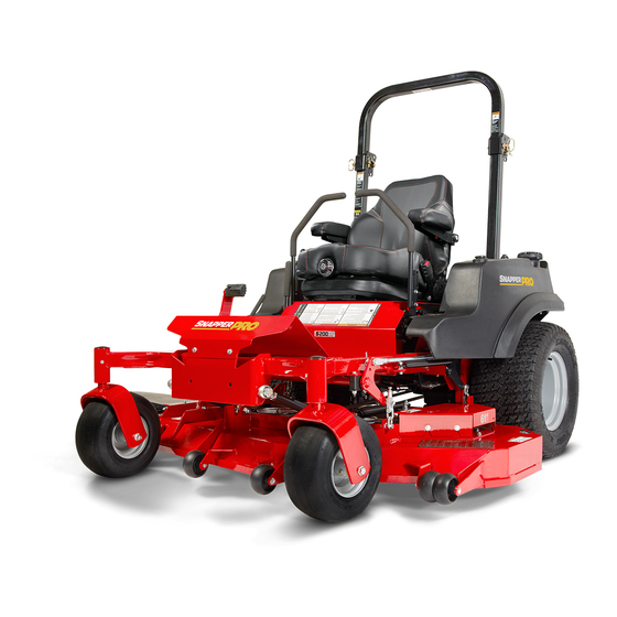
OPERATOR'S MANUAL
Zero-Turn Riding Mower
Model
Description
5901233
S200XTKOH2761
5901280
S200XTBV2761
5901286
S200XTBV3272
5901287
S200XTBV3672
5901367
S200XTBVE2861
5901368
S200XTBV2661
5901379
S200XTBV2661 CAL
5901380
S200XTKAV2661 CAL
5901381
S200XTKOH2761 CAL
5901423
S200XTB2761 CAL
5901424
S200XTBVE2861 CAL
5901511
S200XTBVE3772
5102188
Rev S
Advertisement
Table of Contents
Troubleshooting

Related Manuals for Snapper PRO S200XT


Summary of Contents for Snapper PRO S200XT
- Page 1 S200XTBVE3761 5901511 S200XTBVE3772 This manual is available in Spanish. For a copy, contact your Snapper Pro dealer or www.snapperpro.com. Este manual está disponible en Español. Para obtener una copia, pógase en contacto con su distibuidor Snapper Pro o www.snapperpro.com. 5102188 BRIGGS &...
- Page 2 Thank you for purchasing this quality-built SNAPPER PRO product. We’re pleased that you’ve placed your confidence in the SNAPPER PRO brand. When operated and maintained according to the instructions in this manual, your SNAPPER PRO product will provide many years of dependable service.
-
Page 3: Table Of Contents
Table of Contents Regular Maintenance ..........27 Operator Safety ............2 Maintenance Schedule .........27 Safety Rules and Information .........2 Checking/Adding Fuel ...........28 Safety Decals ............11 Fuel Filter ..............28 Safety Icons ............12 Change Oil & Filter ..........28 Safety Alerty Symbol & Signal Words ....12 Lubrication ............29 Safety Interlock System ........13 Check / Fill Transmission Oil ........30... -
Page 4: Operator Safety
Operator Safety Operating Safety Congratulations on purchasing a superior-quality piece of lawn and garden equipment. Our products are designed and manufactured to meet or exceed all industry standards for safety. Do not operate this machine unless you have been trained. Reading and understanding this operator’s manual is a way to train yourself. - Page 5 Operator Safety Slope Operation Operation on slopes can be dangerous. Using the unit on a slope that is too steep where you do not have adequate wheel traction (and control) can cause sliding, loss of steering, control, and possible rollover. You should not operate on a slope greater than a 5.4 foot rise over a 20 foot length (15 degrees).
- Page 6 Operator Safety Roll Bar Use Keep the roll bar in the raised position and fasten the seat belt. There is no roll over protection when the roll bar is down! Do not jump off if the mower tips (it is safer to be secured by the seat belt with the roll bar raised.) Lower the roll bar only when necessary (such as to temporarily clear a low overhanging obstacle) and...
- Page 7 Operator Safety Fuel and Maintenance Always disengage all drives, shutoff the engine, and remove the key before doing any cleaning, refueling, or servicing. Gasoline and its vapors are extremely flammable. Do not smoke while operating or refueling. Do not add fuel while engine is hot or running.
- Page 8 Operator Safety Read these safety rules and follow them closely. Failure to obey these rules could result in loss of control of unit, severe personal injury or death to you, or bystanders, or damage to property or equipment. This mowing deck is capable of amputating hands and feet and throwing objects. The triangle in text signifies important cautions or warnings which must be followed.
- Page 9 Operator Safety 23. Use care when approaching blind corners, shrubs, 5. Use extra care with grass catchers or other trees or other objects that may obscure vision. attachments. These can change the stability of 24. To reduce fire hazard, keep unit free of grass, the unit.
- Page 10 Operator Safety EMISSIONS where there is an open flame, such as in a water heater. Allow unit to cool before storing. 1. Engine exhaust from this product contains 5. Shut off fuel while storing or transporting. Do not chemicals known, in certain quantities, to cause store fuel near flames or drain indoors.
- Page 11 Operator Safety leaks. Make sure all hydraulic fluid connections To maintain operator roll over protection and roll bar are tight and all hydraulic hoses and lines are in effectiveness: good condition before applying pressure to the • If a ROLL BAR becomes damaged for any reason, system.
- Page 12 Operator Safety WARNING INSPECT BUCKLE & LATCH Failure to properly inspect and maintain the seat belt can cause serious injury or death. INSPECTION AND MAINTENANCE OF THE ROLL BAR SEAT BELT • The seat belt like the ROLL BAR, needs to be periodically inspected to verify that the integrity has not been compromised through normal machine use, misuse, age degradation,...
-
Page 13: Safety Decals
Operator Safety Safety Decals Part No.: 5103595 - Decal, Main Safety Before operating your unit, read the safety decals. The cautions and warnings are for your safety. To avoid a personal injury or damage to the unit, understand and follow all safety decals. WARNING If any safety decals become worn or damaged, Part No.: 7101665 - Decal, Danger... -
Page 14: Safety Icons
Operator Safety Part No.: 5104083 Part No.: 5100683 - Keep ROPS in Raised Position - Decal, Caution, Decal Warning, ROPS Keep Children Away FLDG RL BR Removed Slippery Slopes Dropoffs Safety Alert Symbol & Signal Words The alert symbol is used to identity safety information about hazards that can result in personal injury. -
Page 15: Safety Interlock System
Features & Controls Features and Controls Safety Interlock System Identification Numbers This unit is equipped with safety interlock switches. These safety systems are present for your safety, do not attempt to bypass safety switches, and never tamper with safety devices. Check their operation regularly. -
Page 16: Control Functions And Locations
Features & Controls Zero-Turn Rider Controls Parking Brake Lever Control Functions and Locations DISENGAGE Releases the parking The information below briefly describes the function brake. of individual controls. Starting, stopping, driving, ENGAGE Locks the parking brake. and mowing require the combined use of several controls applied in specific sequences. - Page 17 Features & Controls hydraulic actuator. The hydraulic actuators deactivate throttle when mowing. the transmission so that the unit can be pushed by hand. Both hydraulic actuators must be in the same PTO (Power Take Off) Switch position whether you are driving the unit or pushing it The PTO switch engages and disengages the mower.
-
Page 18: Operation
Operation Operation WARNING General Operating Safety Before first time operation: Never operate on slopes greater than 15°. • Be sure to read all information in the Safety and Select slow ground speed before driving onto Operation sections before attempting to operate a slope. -
Page 19: Checking Tire Pressures
Operation Checking Tire Pressures Tire pressure should be check periodically, and maintained at the level shown in the Specifications chart. Note that these pressure may differ slightly fron the “Max Inflation” stamped on the side-wall of the tires. The pressures shown provide proper traction and extend tire life. -
Page 20: Foot Pedal Adjustment
Operation Foot Pedal Adjustment The deck lift foot pedal can be adjusted to accommodate the operator’s height for optimal comfort. To adjust pedal position: 1. Remove the foot pedal (A, Figure 6) from the pedal mount tab (B). 2. Remove the pedal mount hardware (C) and rotate the tab 180 degrees. -
Page 21: Starting The Engine - Carbuerated Models
Operation parking brake and make sure the PTO switch is Starting the Engine - Carbuerated Models disengaged and the ground speed control levers are locked in the neutral position. WARNING 2. Position the throttle control midway between slow If you do not understand how a specific control and fast positions. -
Page 22: Pushing The Rider By Hand
Operation Pushing the Rider By Hand NOTICE Do NOT tow rider. Towing the units will cause hydraulic transmission damage. Do not use another vehicle to push or pull this unit. 1. Disengage the PTO, engage the parking brake, turn the ignition OFF, and remove the key. 2. -
Page 23: Zero Turn Driving Practice
Operation Smooth Travel Zero Turn Driving Practice The lever controls of The lever controls of the Zero Turn rider are the Zero Turn rider are responsive, and learning to gain a smooth and efficient responsive. control of the rider’s forward, reverse, and turning movements will take some practice. - Page 24 Operation Practice Turning Around a Corner Practice Turning In Place While traveling forward allow one handle to gradually To turn in place, “Zero Turn,” gradually move one return back toward neutral. Repeat several times. ground speed control lever forward from neutral and one lever back from neutral simultaneously.
-
Page 25: Mowing
Operation Mowing 1. Engage the parking brake. Make sure that the PTO switch is disengaged, the ground speed control levers are locked in the NEUTRAL position and the operator is in the seat. 2. Start the engine. See Starting the Engine. 3. -
Page 26: Mowing Methods
Operation When and How Often to Mow The time of day and condition of the grass greatly affect the results you’ll get when mowing. For the best results, follow these guidelines: 1. Mow when the grass is between three and five inches high. -
Page 27: Attaching A Trailer
Operation Attaching A Trailer Proper Mulching Mulching consists of a mower deck which cuts and The maximum weight of a towed trailer should be recuts clippings into tiny particles and which then less than 200 lbs (91kg). Secure the trailer with a blows them down INTO the lawn. -
Page 28: Storage
Operation Storage WARNING Temporary Storage (30 Days Or Less) Never store the unit, with gasoline in engine or fuel tank, in a heated shelter or in enclosed, Remember, the fuel tank will still contain some poorly ventilated enclosures. Gasoline fumes gasoline, so never store the unit indoors or in any may reach an open flame, spark or pilot light other area where fuel vapor could travel to any ignition... -
Page 29: Regular Maintenance
Maintenance Regular Maintenance Maintenance Schedule The following schedule should be followed for normal care of your rider and mower. You will need to keep a record of your operating time. Determining operating time is easily accomplished by observing the elapsed time recorded by the hour meter. -
Page 30: Checking/Adding Fuel
Maintenance Checking / Adding Fuel WARNING To add fuel: Gasoline is highly flammable and must be 1. Remove the fuel cap. handled with care. Never fill the tank when the 2. Fill the tank to about 1-1/2” (3,81 cm) of the bottom engine is still hot from recent operation. -
Page 31: Lubrication
Maintenance Lubrication Lubricate the unit at the locations shown in Figures 20 through 23 as well as the following lubrication points. Grease: • front caster wheel axles & yokes • deck lift pivot blocks • mower deck spindles • mower deck idler arm Use grease fittings when present. -
Page 32: Check / Fill Transmission Oil
Maintenance Check / Fill Transmission Oil Level This unit is equipped with two transmission oil tanks. One transmission oil tank only supplies oil to one transmission. The level of oil in both transmission tanks must be check, and if necessary, filled. Oil Type: SAE 20W-50 motor oil 1. -
Page 33: Purging Air From The Hydraulic System
Maintenance Purging the Air from the Hydraulic System Due to the effects air has on efficiency in hydraulic drive systems, it is critical that it be purged from the system. These purge procedures should be implemented any time a hydraulic system has been opened to facilitate maintenance or any additional oil has been added to the system. -
Page 34: Servicing The Mower Blades
Maintenance Servicing The Mower Blades Removing the Mower Blade CAUTION Avoid injury! Mower blades are sharp. • Always wear gloves when handling mower blades or working near blades. 1. To remove the mower blade, use a 1” wrench on the flats of the spindle shaft and remove the mower blade mounting bolt with a 15/16”... - Page 35 Maintenance Sharpening the Mower Blade CAUTION Avoid injury! Mower blades are sharp. • Always wear gloves when handling the mower blades. • Always wear safety eye protection when grinding. Figure 29. Sharpening the Mower Blade 1. Sharpen the mower blades with grinder, hand file, A.
-
Page 36: Ground Speed Control Lever Adjustment
Maintenance Ground Speed Control Lever Adjustment The control levers can be adjusted in three ways. The alignment of the control levers, the placement of the levers (how close the ends are to one another) and the height of the levers can be adjusted. To Adjust the Handle Alignment Loosen the mount bolts (A, Figure 32) and pivot the lever(s) (B) to align with each other. -
Page 37: Neutral Adjustment
Maintenance Neutral Adjustment If the tractor “creeps” while the ground speed control levers are locked in NEUTRAL, then it may be necessary to adjust the linkage rod. NOTE: Perform this adjustment on a hard, level surface such as a concrete floor. 1. -
Page 38: Deck Rod Timing Adjustment - 61" Models
9. Position the set collar 1/8” (0,3 cm) away from the parking brake bracket and tighten. If this does not correct the braking problem, see your Snapper Pro dealer. Deck Rod Timing Adjustment - 61” Models 1. Park the machine on a flat, level surface. -
Page 39: Deck Rod Timing Adjustment - 72" Models
Maintenance Deck Rod Timing Adjustment - 72” Models 1. Park the machine on a flat, level surface. Disengage the PTO, engage the parking brake, turn off the engine, and remove the ignition key. Rear tires must be inflated to 15 psi (1,03 bar). 2. -
Page 40: Deck Leveling Adjustment
Maintenance Deck Leveling Adjustment Before adjusting the deck level, the deck lift rod timing must be checked and/or adjusted. Determining if the Deck Leveling Needs to be Adjusted: WARNING Avoid Injury! Mower blades are sharp. Always wear gloves when handling blades or working near blades. - Page 41 Maintenance tighten the nuts. 5. Repeat the process for the other side of the unit. 6. Remove all the blocks and spacers for under the mower deck. 7. Perform the Determining if the Deck Leveling Needs to be Adjusted procedure to verify that the deck has been leveled correctly.
-
Page 42: Mower Belt Replacement - 61" Mower Decks
Maintenance Mower Belt Replacement - 61” Mower 61” Decks NOTICE To avoid damaging belts, DO NOT PRY BELTS OVER PULLEYS. 1. Park the tractor on a smooth, level surface such as a concrete floor. Disengage the PTO, engage the parking brake, turn off the engine, and remove the ignition key. -
Page 43: Mower Belt Replacement - 72" Mower Decks
Maintenance Mower Belt Replacement - 72” Mower 72” Decks NOTICE To avoid damaging belts, DO NOT PRY BELTS OVER PULLEYS. 1. Park the tractor on a smooth, level surface such as a concrete floor. Disengage the PTO, engage the parking brake, turn off the engine, and remove the ignition key. -
Page 44: Checking / Adjusting The Mower Belt Idler
Maintenance Checking / Adjusting the Mower Belt Idler Tensioning Spring Length - All Models Mower Deck Belt Tensioning Spring Length Deck Serial Number Measurement Size 61” 2016953545 & Below 7-1/4” ± 1/8” (18,42 cm ± 0,13 cm) 61” 2016953546 & Above 12-1/2”... -
Page 45: Hydraulic Pump Drive Belt Replacement
Maintenance Hydraulic Pump Drive Belt Replacement 1. Park the tractor on a smooth, level surface such as a concrete floor. Disengage the PTO, engage the parking brake, turn off the engine, and remove the ignition key. 6 3/8” 2. Remove the PTO drive belt (see MOWER BELT (16,2 cm) REPLACEMENT for removal instructions). -
Page 46: Electronic Fuel Injection (Efi) System - Fuel Injected Models
Maintenance Electronic Fuel Injection (EFI) System - CAUTION Fuel Injected Models Do not disconnect or reconnect ECU EFI is an electronically-controlled fuel management wiring harness connector or any individual system which is monitored by an Electronic Control components with the ignition switch in the Unit (ECU). -
Page 47: Electric Pto Clutch Adjustment
Maintenance Electric PTO Clutch Adjustment This procedure pertains to models equipped with a 37 gross HP* Briggs & Stratton engine. WARNING To avoid serious injury, perform adjustments only with the engine stopped, the ignition key removed, and the unit parked on level ground. -
Page 48: Battery Service
Maintenance Battery Service spewing of electrolyte occurs, the charging rate must be reduced or temporarily halted to prevent WARNING battery damage. 6. Charge the battery until fully charged (until the Keep open flames and sparks away from the specific gravity of the electrolyte is 1.250 or higher battery;... - Page 49 Maintenance 11. Remove the other cable by disconnecting at the WARNING discharged battery first and then disconnect the opposite end from the booster battery. For your personal safety, use extreme care when jump starting. Never expose battery to 12. Discard the damp cloths that were placed over the open flame or electric spark –...
-
Page 50: Troubleshooting
Troubleshooting Troubleshooting Troubleshooting Chart WARNING While normal care and regular maintenance will To avoid serious injury, perform maintenance extend the life of your equipment, prolonged or on the tractor or mower only when the engine constant use may eventually require that service be is stopped and the parking brake engaged. -
Page 51: Troubleshooting The Mower
Troubleshooting Rider Troubleshooting Continued. Problem Cause Remedy Engine runs, but rider will 1. Transaxles are disengaged. 1. Engage the transaxles. See Pushing not drive. the Rider by Hand. 2. Belt is broken. 2. See Drive Belt Replacement. 3. Drive belt slips. 3. -
Page 52: Troubleshooting Common Cutting Problems
Troubleshooting Troubleshooting Common Cutting Problems PROBLEM CAUSE REMEDY Streaking 1. Sharpen your blades. 1. Blades are not sharp. 2. Replace your blades. 2. Blades are worn down too far. 3. Always mow at FULL throttle. 3. Engine speed is too slow. 4. -
Page 53: Specifications
Specifications Specifications Model ECV749-3022 Displacement 45.6 Cu. in (747 cc) Electrical System 12 volt, 20 amp. Alternator; NOTE: Specifications are correct at time of printing Battery: 340 cca and are subject to change without notice. Oil Capacity 2.0 US qt. (1.9 L) w/ filter ENGINE 30 Gross HP* Briggs &... - Page 54 Specifications to-engine variability. Given the wide array of products on which engines are placed, the gasoline engine may not develop the rated gross power when used in a given piece of power equipment. This difference is due to a variety of factors including, but not limited to, the variety of engine components (air cleaner, exhaust, charging, cooling, carburetor, fuel pump, etc.), application limitations, ambient operating conditions (temperature, humidity, altitude), and engine-...
-
Page 55: Slope Identification Guide
ALIGN THIS EDGE WITH A VERTICAL SURFACE (TREE, POLE, FENCE POST, BUILDING, ETC) - Page 56 Notes...
- Page 57 Notes...
- Page 59 ABOUT YOUR WARRANTY We welcome warranty repair and apologize to you for being inconvenienced. Warranty service is available only through SNAPPER PRO Authorized Service Dealers. Most warranty repairs are handled routinely, but sometimes requests for warranty service may not be appropriate. This warranty only covers defects in materials or workmanship.
- Page 60 OPERATOR’S MANUAL BRIGGS & STRATTON PRODUCTS GROUP 5375 NORTH MAIN STREET MUNNSVILLE, NY 13409 800 933 6175...
Need help?
Do you have a question about the PRO S200XT and is the answer not in the manual?
Questions and answers