
Related Manuals for OSS OSS-PCIe-HIB35-X4


Summary of Contents for OSS OSS-PCIe-HIB35-X4
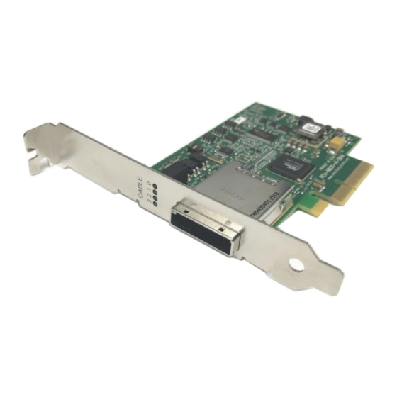
- Page 1 PCIe x4 Gen2 Host Cable Adapter with PCIe Switch Model: OSS-PCIe-HIB35-x4 Installation Guide SKU: OSS-PCIe-HIB35-X4 www.onestopsystems.com...
-
Page 2: Table Of Contents
2.1.5 ATX Power Supply 2.2 Software Requirement Installation Procedures Configure Dipswitches Install HIB Host card Install HIB Target card Install PCIe card Install link cable Connect ATX Power Supply Power ON the system Verify Hardware LED Definition LED Indicator Scenarios OSS-PCIe-HIB35x4 | 2... - Page 3 One Stop Systems OSS-PCIe-HIB2-x4-P and HIB25-x4-H Software Installation How to Get More Help 7.1 Contacting Technical Support 7.2 Returning Merchandise 7.3 Online Support Resources OSS-PCIe-HIB35x4 | 3...
-
Page 4: Preface
Disclaimer: We have attempted to identify most situations that may pose a danger, warning, or caution condition in this manual. However, the company does not claim to have covered all situations that might require the use of a Caution, Warning, or Danger indicator. OSS-PCIe-HIB35x4 | 4... -
Page 5: Safety Instructions
Also, before connecting a cable, make sure both connectors are correctly oriented and aligned. CAUTION Do not attempt to service the system yourself except as explained in this manual. Follow installation instructions closely. OSS-PCIe-HIB35x4 | 5... - Page 6 Handle all sensitive components at an ESD workstation. If possible, use anti-static floor pads and workbench pads. Handle components and boards with care. Do not touch the components or contacts on a board. Hold a board by its edges or by its metal mounting bracket. OSS-PCIe-HIB35x4 | 6...
-
Page 7: Introduction
It operates in upstream or downstream mode with Dipswitch setting change. The host cable adapter installs in the PCIe slot of a host server and the target cable adapter installs in the Target slot / Upstream slot of the OSS backplane. -
Page 8: Overview
One Stop Systems Overview OSS-PCIe-HIB35x4 | 8... -
Page 9: Pcie Card Edge X4
Power is provided by the PCI-e card slot. Power required by internal components of OSS-PCIe-HIB-35-x4 is estimated to be 4 watts when both ports are fully linked and operating in Gen2 mode. Cable power is to be provided per PCIe cable specification. When an active cable (powered transceiver) is used, additional power is required from the PCI-e card slot. -
Page 10: Link Leds
The second set of 4 LEDs show the PCIe lane width connection through the card edge to host system. LEDs 0-3 represent lanes 1-4. These LEDs will be solid when a link is established and off when there is NO link. If an LED is flashing, the link is training unsuccessfully. OSS-PCIe-HIB35x4 | 10... -
Page 11: 1.10 Block Diagram
One Stop Systems 1.10 Block Diagram 1.11 Dimensions OSS-PCIe-HIB35x4 | 11... -
Page 12: Hib Card Operating Modes
PCIe slot. Use Gen2 x16, x8 or x4 PCIe slot. When the card dipswitch is configured to operate in Host mode, it cannot be installed in a target slot (Upstream slot) on the OSS expansion backplane. It must be installed in the computer’s motherboard PCIe slot. OSS-PCIe-HIB35x4 | 12... -
Page 13: Pci Express X4 Card Edge Connector Pin Outs
PERST# Mechanical Key RSVD REFCLK+ PETp0 REFCLK- PETn0 PERp0 PRSNT2# PERn0 End of the x1 Connector PETp1 RSVD PETn1 PERp1 PERn1 PETp2 PETn2 PERp2 PERn2 PETp3 PETn3 PERp3 RSVD PERn3 PRSNT2# RSVD End of the x4 Connector OSS-PCIe-HIB35x4 | 13... -
Page 14: X4 Cable Wire Connections / Pin Outs
PETn1 PERp2 Differential Pair PETp2 PERn2 PETn2 PERp3 Differential Pair PETp3 PERn3 PETn3 PWR_RTN PWR_RTN PWR_RTN PWR_RTN CWAKE# Hook-up Wire CWAKE# CPERST# Hook-up Wire CPERST# Backshell Chassis Ground Overall Cable Braid Chassis Ground Backshell *NC: Not Connected OSS-PCIe-HIB35x4 | 14... -
Page 15: X4 Cable Signal Descriptions
Power: Provides local power for in-cable redriver circuits. Only needed on long cables (Power does not go across the cable.) PWR_RTN Provides local power return path for PWR pins. CWAKE# Cable WAKE CPERST# Cable PCI Express Reset OSS-PCIe-HIB35x4 | 15... -
Page 16: Hardware Requirements
NOTE: The HIB35-x4 card works in pair (one as host card and other as target card) One x4 iPass cable OSS Expansion chassis with Gen2 backplane, or OSS expansion backplane and power supply. 2.1.1 HIB35-x4 card (Host and Target) A pair of HIB35-x4 card (Target and Host cards) 2.1.2... -
Page 17: Expansion Chassis / Backplanes
2.1.5 ATX Power Supply If you are using an OSS backplane with the HIB35-x4 card you need a power supply unit to provide power. A standard ATX power supply will work with the boards. Software Requirement Computer running Windows 7, 8, 10 and or Server... -
Page 18: Installation Procedures
Power down the host computer first before installing the host card. Do not install the host card while the computer is ON. Install the HIB35-x4 host card into the available PCIe slot in the computer’s motherboard. Use a x4, x8 or x16 Gen2 PCIe slot. Make sure to secure the card with a screw. OSS-PCIe-HIB35x4 | 18... -
Page 19: Install Hib Target Card
Do not plug in the target card while expansion unit or the expansion backplane is ON as this can damage the board. Turn OFF the unit first before installing the card. The HIB Target card will only work in the OSS backplane “Upstream” slot. It will not function in the downstream slot or the end-point slot of the backplane. -
Page 20: Install Pcie Card
One Stop Systems Install PCIe card Plug-in your 3rd party PCIe card in the expansion backplane. Use the downstream slot on the OSS backplane. See photos below showing where the location of the downstream slot / end-point slot. Install link cable ... -
Page 21: Connect Atx Power Supply
If you are using an expansion chassis, the power supply is already part of the unit. You can skip this step. If you are using an expansion backplane, plug-in the ATX power supply cable into the 24pin ATX power connector on the OSS board. -
Page 22: Verify Hardware
LEDs on boards and bracket are illuminated. In this setup, the host is not powered UP or the host is not connected to the target. Bracket LED: 1 is lit as solid green Board LEDs: PWR= Solid Green RST = Solid Red CRST = Solid Red 0 and 1 = Solid Green OSS-PCIe-HIB35x4 | 22... - Page 23 When Host computer is shutdown, all the LEDs on the Host cards are instantly turns OFF. The bracket LED (Link Status LED) is OFF and the RST and CRST LEDs comes ON as solid RED, see photos below. OSS-PCIe-HIB35x4 | 23...
-
Page 24: Oss-Pcie-Hib2-X4-P And Hib25-X4-H
One Stop Systems OSS-PCIe-HIB2-x4-P and HIB25-x4-H The OSS-PCIe-HIB2-x4-P (as Host card) and OSS-PCIe-HIB25-x4-H (as Host card) are not compatible with the OSS-PCIe-HIB35x4 (Target card). Due to hardware incompatibility both cards will not link up when be paired with OSS-PCIe-HIB35x4 (Target card) ... -
Page 25: Software Installation
One Stop Systems Software Installation No software or driver is required for the Host Adapter card. OSS-PCIe-HIB35x4 | 25... -
Page 26: How To Get More Help
If you need technical support, product assistance or have a technical inquiry we encourage you to submit it on-line using our Technical Support Form. If you need to send a unit for repair or diagnostic evaluation, fill out our RMA (Return Material Authorization) online request form. https://www.onestopsystems.com/support OSS-PCIe-HIB35x4 | 26... - Page 27 One Stop Systems OSS-PCIe-HIB35x4 | 27...
Need help?
Do you have a question about the OSS-PCIe-HIB35-X4 and is the answer not in the manual?
Questions and answers