
Related Manuals for Johnson Controls TCSC Series


Summary of Contents for Johnson Controls TCSC Series
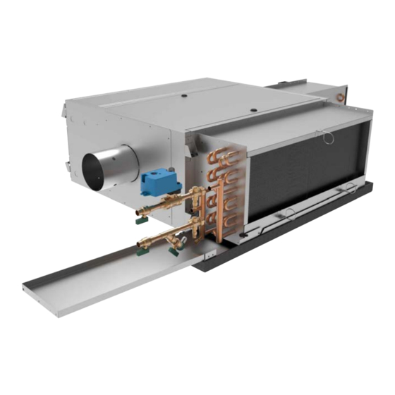
- Page 1 FAN POWERED SENSIBLE COOLING VAV TERMINALS INSTALLATION, OPERATION & MAINTENANCE New Release Form 130.13-NOM8 (1021) MODEL TCSC...
-
Page 2: Table Of Contents
FACE AREA, FREE AREA, AND FILTER SIZES ................39 GENERAL TROUBLESHOOTING GUIDELINES ..................40 VALVE CALIBRATION CHARTS .......................41 FAN CFM CALIBRATION CURVE EXAMPLES ..................41 TERMINAL UNIT WEIGHTS ........................43 FACTORY REPLACEMENT PARTS AND WARRANTY ................44 COMPONENT INSTALLATION, OPERATION AND MAINTENANCE APPENDIX ........45 JOHNSON CONTROLS... - Page 3 WARNING indicates a potentially haz- NOTE is used to highlight additional ardous situation which, if not avoided, information which may be helpful to could result in death or serious injury. you. JOHNSON CONTROLS...
-
Page 4: Safety Considerations
Check that rigging and lifting equip- ment can safely support the equipment assembly and component weights. JOHNSON CONTROLS... -
Page 5: Inspection
Do not handle by equipment’s heating elements, as permanent damage will occur. JOHNSON CONTROLS... -
Page 6: Sequence Of Operation
3. Series flow with sensible cooling coil mounted on false ceiling grid. Suspension devices are field supplied, the intake opening, flanged discharge opening. sized and designed by others. Johnson Controls will not accept responsibility for equipment mounting supports. Series Flow Equipment must be installed in a level horizontal plane. -
Page 7: Duct Connections
After all connections are made, check that the entire then be tested for leaks. Since some components are ductwork system is airtight. In some high-pressure not designed to hold pressure with a gas, hydronic systems, duct sealer may be necessary. systems should be tested with water. JOHNSON CONTROLS... -
Page 8: Drip Pan & Auxiliary Drip Pan Removal
Which Secure The Auxiliary Drip Pan To The Drip Pan. Step 2: Visually Locate Drip Pan Retention Studs. Step 2: Remove Retaining Screws And Carefully Remove The Auxiliary Drip Pan From The Drip Pan. Step 3: Apply Slight Upward Pressure to Drip Pan. JOHNSON CONTROLS... -
Page 9: Cooling/Heating Medium Connections
If necessary, you can change hot water coil connection to coil headers. handing on one and two row coils from left-hand to right- hand (and vice-versa) by rotating the coil “like a steering wheel” 180° about its central axis when facing the fins. JOHNSON CONTROLS... -
Page 10: Electrical Connections
The manufacturer assumes no responsibility for any damages and/or injuries resulting from improperly field installed or wired components. Prior to unit startup, ensure that all wiring connections to the terminal strip are securely tightened. JOHNSON CONTROLS... -
Page 11: Access Door Reassignment
0.1” wg. and 0.2” on 3/4hp and 3. Remove electrical enclosure top access panel. larger (see fan curves located on the Johnson Controls 4. Reinstall electrical enclosure top access panel to website for specifics). All foreign materials should be top of unit. -
Page 12: Service And Clearance Requirements
TITLE: SUBMITTAL DRAWING MODEL TCSC SIZES 07-23, ELECTRIC HEAT, ALL DRAWINGS ARE SUBJECT TO CHANGE EXTERNAL SPACE REQUIREMENTS WITHOUT PRIOR NOTICE JOHNSON CONTROLS DATE SHEET DRAWING NO DO NOT SCALE DRAWING DIMENSIONS ARE IN INCH [MM] FORMAT THIS DRAWING CONTAINS PROPRIETARY DATA. UNAUTHORIZED DISCLOSURE,... - Page 13 4. Maintain clearance per NEC (in direction of arrow). TITLE: SUBMITTAL DRAWING MODEL TCSC SIZES 07-23, ELECTRIC HEAT, ALL DRAWINGS ARE SUBJECT TO CHANGE EXTERNAL SPACE REQUIREMENTS WITHOUT PRIOR NOTICE JOHNSON CONTROLS DATE SHEET DRAWING NO DO NOT SCALE DRAWING...
- Page 14 EC motor control. TITLE: SUBMITTAL DRAWING MODEL TCSC SIZES 07-23, HOT WATER COIL, ALL DRAWINGS ARE SUBJECT TO CHANGE EXTERNAL SPACE REQUIREMENTS WITHOUT PRIOR NOTICE JOHNSON CONTROLS DATE SHEET DRAWING NO DO NOT SCALE DRAWING...
- Page 15 4. Maintain clearance per NEC (in direction of arrow). TITLE: SUBMITTAL DRAWING MODEL TCSC SIZES 07-23, HOT WATER COIL, ALL DRAWINGS ARE SUBJECT TO CHANGE EXTERNAL SPACE REQUIREMENTS WITHOUT PRIOR NOTICE JOHNSON CONTROLS DATE SHEET DRAWING NO DO NOT SCALE DRAWING...
- Page 16 3. Standard Electrical Enclosure shown, 90° Electrical Enclosure Unit same as shown. TITLE: SUBMITTAL DRAWING MODEL TCSC DRAIN & AUX PAN, ALL DRAWINGS ARE SUBJECT TO CHANGE EXTERNAL SPACE REQUIREMENTS WITHOUT PRIOR NOTICE JOHNSON CONTROLS DATE SHEET DRAWING NO DO NOT SCALE DRAWING...
-
Page 17: Chilled Water Coil Connections
MODEL TCSC, CHILLED WATER, 3/8" ALL DRAWINGS ARE SUBJECT TO CHANGE ALL DRAWINGS ARE SUBJECT TO CHANGE DIA COIL CONNECTIONS 2 - 4 ROWS WITHOUT PRIOR NOTICE WITHOUT PRIOR NOTICE JOHNSON CONTROLS DATE DATE SHEET SHEET DRAWING NO DRAWING NO... - Page 18 WITHOUT PRIOR NOTICE DATE DATE SHEET SHEET DRAWING NO DRAWING NO JOHNSON CONTROLS DO NOT SCALE DRAWING DO NOT SCALE DRAWING DIMENSIONS ARE IN INCH [MM] FORMAT DIMENSIONS ARE IN INCH [MM] FORMAT THIS DRAWING CONTAINS PROPRIETARY DATA. UNAUTHORIZED DISCLOSURE,...
- Page 19 MODEL TCSC, CHILLED WATER, 1/2" DIA ALL DRAWINGS ARE SUBJECT TO CHANGE ALL DRAWINGS ARE SUBJECT TO CHANGE COIL CONNECTIONS 2 - 4 ROWS WITHOUT PRIOR NOTICE WITHOUT PRIOR NOTICE JOHNSON CONTROLS DATE DATE SHEET SHEET DRAWING NO DRAWING NO...
- Page 20 DATE DATE SHEET SHEET DRAWING NO DRAWING NO JOHNSON CONTROLS DO NOT SCALE DRAWING DO NOT SCALE DRAWING THIS DRAWING CONTAINS PROPRIETARY DATA. UNAUTHORIZED DISCLOSURE, REPRODUCTION, OR USE IS STRICTLY PROHIBITED WITHOUT WRITTEN PERMISSION. DIMENSIONS ARE IN INCH [MM] FORMAT DIMENSIONS ARE IN INCH [MM] FORMAT THIS DRAWING CONTAINS PROPRIETARY DATA.
-
Page 21: Hot Water Coil Connections
TITLE: SUBMITTAL DRAWING MODEL TCSB, TCSQ & TCSC ALL DRAWINGS ARE SUBJECT TO CHANGE HOT WATER, 3/8" DIA COIL CONNECTIONS WITHOUT PRIOR NOTICE JOHNSON CONTROLS DATE SHEET DRAWING NO DO NOT SCALE DRAWING THIS DRAWING CONTAINS PROPRIETARY DATA. UNAUTHORIZED DISCLOSURE,... - Page 22 For multiple circuit coils refer sheet no 1. [46] [60] TITLE: SUBMITTAL DRAWING MODEL TCSB, TCSQ & TCSC ALL DRAWINGS ARE SUBJECT TO CHANGE HOT WATER, 3/8" DIA COIL CONNECTIONS WITHOUT PRIOR NOTICE JOHNSON CONTROLS DATE SHEET DRAWING NO DO NOT SCALE DRAWING...
- Page 23 For two row two circuit coils refer sheet no 3. [179] [115] [82] [114] TITLE: SUBMITTAL DRAWING MODEL TCSB, TCSQ & TCSC ALL DRAWINGS ARE SUBJECT TO CHANGE HOT WATER,1/2" DIA COIL CONNECTIONS WITHOUT PRIOR NOTICE JOHNSON CONTROLS DATE SHEET DRAWING NO DO NOT SCALE DRAWING...
- Page 24 For two row two circuit coils refer sheet no 3. 1-3/4" 2-3/8" 15/20/23 [46] [60] TITLE: SUBMITTAL DRAWING MODEL TCSB, TCSQ & TCSC ALL DRAWINGS ARE SUBJECT TO CHANGE HOT WATER,1/2" DIA COIL CONNECTIONS WITHOUT PRIOR NOTICE JOHNSON CONTROLS DATE SHEET DRAWING NO DO NOT SCALE DRAWING...
- Page 25 For single circuit coils refer sheet no 2. [38] [74] TITLE: SUBMITTAL DRAWING MODEL TCSB, TCSQ & TCSC ALL DRAWINGS ARE SUBJECT TO CHANGE HOT WATER,1/2" DIA COIL CONNECTIONS WITHOUT PRIOR NOTICE JOHNSON CONTROLS DATE SHEET DRAWING NO DO NOT SCALE DRAWING...
-
Page 26: Valve Package Coil Connections
COIL, VALVE PACKAGE CONNECTIONS WITHOUT PRIOR NOTICE DATE SHEET DRAWING NO DO NOT SCALE DRAWING JOHNSON CONTROLS DIMENSIONS ARE IN INCH [MM] FORMAT THIS DRAWING CONTAINS PROPRIETARY DATA. UNAUTHORIZED DISCLOSURE, 4/29/2021 PAGE 1 OF 3 10-80049-J REPRODUCTION, OR USE IS STRICTLY PROHIBITED WITHOUT WRITTEN PERMISSION. - Page 27 COIL, VALVE PACKAGE CONNECTIONS WITHOUT PRIOR NOTICE DATE SHEET DRAWING NO DO NOT SCALE DRAWING JOHNSON CONTROLS DIMENSIONS ARE IN INCH [MM] FORMAT THIS DRAWING CONTAINS PROPRIETARY DATA. UNAUTHORIZED DISCLOSURE, 4/29/2021 PAGE 2 OF 3 10-80049-J REPRODUCTION, OR USE IS STRICTLY PROHIBITED WITHOUT WRITTEN PERMISSION.
- Page 28 WITHOUT PRIOR NOTICE DATE SHEET DRAWING NO DO NOT SCALE DRAWING DIMENSIONS ARE IN INCH [MM] FORMAT JOHNSON CONTROLS THIS DRAWING CONTAINS PROPRIETARY DATA. UNAUTHORIZED DISCLOSURE, 4/29/2021 PAGE 3 OF 3 10-80049-J REPRODUCTION, OR USE IS STRICTLY PROHIBITED WITHOUT WRITTEN PERMISSION.
- Page 29 MODEL TCSB, TCSQ & TCSC 1/2” DIA, HW ALL DRAWINGS ARE SUBJECT TO CHANGE COIL, VALVE PACKAGE CONNECTIONS WITHOUT PRIOR NOTICE DATE SHEET DRAWING NO JOHNSON CONTROLS DO NOT SCALE DRAWING DIMENSIONS ARE IN INCH [MM] FORMAT THIS DRAWING CONTAINS PROPRIETARY DATA. UNAUTHORIZED DISCLOSURE,...
- Page 30 COIL, VALVE PACKAGE CONNECTIONS WITHOUT PRIOR NOTICE DATE SHEET DRAWING NO DO NOT SCALE DRAWING JOHNSON CONTROLS DIMENSIONS ARE IN INCH [MM] FORMAT THIS DRAWING CONTAINS PROPRIETARY DATA. UNAUTHORIZED DISCLOSURE, 4/29/2021 PAGE 2 OF 3 10-80051-J +/- 1/8 [3] UNLESS OTHERWISE NOTED...
- Page 31 DO NOT SCALE DRAWING DIMENSIONS ARE IN INCH [MM] FORMAT THIS DRAWING CONTAINS PROPRIETARY DATA. UNAUTHORIZED DISCLOSURE, 4/29/2021 PAGE 3 OF 3 10-80051-J JOHNSON CONTROLS REPRODUCTION, OR USE IS STRICTLY PROHIBITED WITHOUT WRITTEN PERMISSION. +/- 1/8 [3] UNLESS OTHERWISE NOTED...
-
Page 32: Inspection And Startup Checklist
Connect Supply and Return Pipe to Correct □ Reinstall All Covers & Access Panels Coil Connections 4. DUCTWORK CONNECTIONS □ Install Ductwork, Fittings & Grilles as Required □ Proper Supply/Return Grille Types & Sizes Used □ Insulate All Ductwork as Required JOHNSON CONTROLS... -
Page 33: Maintenance
Damper shaft indicator in horizontal position, indicat- ing fully open damper blade Step 1: Disconnect all electrical power to the equipment, lock out and tag out power source. Locate top and/or bottom panel quarter-turn latches, turn counter-clockwise to disengage. JOHNSON CONTROLS... -
Page 34: Coil
Remove motor/belly band, perform motor/blower maintenance as required. To reassemble rial does not contact other areas of the equipment or building. Properly dispose of all contaminat- and reinstall motor/blower assembly, follow steps 1-4 in ed materials. reverse fashion. JOHNSON CONTROLS... -
Page 35: Removal And Replacement
Step 1: Disconnect all electrical power to the equipment, lock out and tag out power source. Locate electric heat wiring harness cover on the side of the discharge duct. JOHNSON CONTROLS... -
Page 36: Optional Item Installation
3. Secure bracket into side of pan using self-tapping sheet metal screw through upper hole in bracket. 4. Ensure float switch assembly is firmly secured to bracket. Ensure top of float is below rim of pan. JOHNSON CONTROLS... -
Page 37: Moisture Sensor
The sensor also has a set of normally open contacts which will have the opposite behavior (between WHT and GRY wires). Test switch sensitivity by filling pan and confirm signal changes when water reaches height of contacts. Moisture sensor installed JOHNSON CONTROLS... -
Page 38: Filters
Replace with a new filter, and once in place, rotate the filter Tool-free removable filter clips allow for use of 1” or 2” clips 180-degrees back to their original position. filter sizes JOHNSON CONTROLS... -
Page 39: Filters, Throwaway & Pleated
1. All filters are an optional feature. For optimal unit performance, filter type should be selected during the unit selection and ordering process. 2. Filter sizes are nominal, measured in inches [millimeters] 3. Coil and filter face areas are measured in square feet [square meters] JOHNSON CONTROLS... -
Page 40: General Troubleshooting Guidelines
Problems with Additional Stages Check contactors for open coil Check for damaged elements Incorrect CFM Check for blocked duct or location of heater Heater with SSR Does Incorrect Signal Applied Verify signal input Not Operate Interface Board Fuse Blown Replace fuse JOHNSON CONTROLS... -
Page 41: Valve Calibration Charts
FORM 130.13-NOM8 (1021) VALVE CALIBRATION CHARTS APPLICABLE CALIBRATION CHARTS ARE AFFIXED TO EACH UNIT, AND MAY ALSO BE OBTAINED BY CONTACTING YOUR JOHNSON CONTROLS REPRESENTIVE. PROBE DIFFERENTIAL PRESSURE (INCHES W.G.) JOHNSON CONTROLS... -
Page 42: Fan Cfm Calibration Curve Examples
0.90 Low-Min 13 % 3.0 VDC 2.5 VDC 0.80 0.70 FOR REFERENCE ONLY REFER TO UNIT LABEL FOR 0.60 UNIT SPECIFIC FAN CALIBRATION 0.50 Low-Min 0.40 0.30 0.20 0.10 0.00 1000 1200 1400 Airflow (SCFM) 43-10072-11, Rev. A JOHNSON CONTROLS... -
Page 43: Terminal Unit Weights
ELECTRIC SIZE SINGLE WALL HEAT 1 ROW 2 ROW 3 ROW 4 ROW 2 ROW 3 ROW 4 ROW 6 ROW 8 ROW 0407 0410 0507 0510 0607 0610 0615 0620 0623 0815 0820 0823 1015 1020 1023 JOHNSON CONTROLS... -
Page 44: Factory Replacement Parts And Warranty
Replacement parts may be purchased through the local Sales Representative. Contact your Johnson Controls sales representative for authorization to return any parts such as defective parts Contact the your Johnson Controls Sales Representative replaced in warranty. -
Page 45: Component Installation, Operation And Maintenance Appendix
For the supplemental Installation, Operation and Maintenance manuals listed above, please con- tact your local Johnson Controls Sales Representative. For configurable VAV DDC Controls, MAP Gateway Tool Quick Start Guides, and related IOMs, please contact your local Johnson Controls Sales Representative. JOHNSON CONTROLS... - Page 46 Catalog: 130.13-NOM8 (1021) New Release © 2021 Johnson Controls P.O. Box 423, Milwaukee, WI 53201 www.johnsoncontrols.com...
Need help?
Do you have a question about the TCSC Series and is the answer not in the manual?
Questions and answers