Table of Contents
Advertisement
Quick Links
Advertisement
Table of Contents

Related Manuals for Fungilab VISCOLED ADVANCE Series


Summary of Contents for Fungilab VISCOLED ADVANCE Series
- Page 1 VISCOLEAD SERIES ADVANCE...
- Page 2 VISCOLEAD SERIES ADVANCE Rotational Viscometer Software Version: 5.2 Manual Version:1.3 Instruction Manual FUNGILAB S.A. C/ Constitució, 64 FUNGILAB INC Pol. Ind. Les Grases 89 K Cabot Ct. Hauppauge 08980 Sant Feliu de Llobregat 11788 NY (US) Barcelona, SPAIN Phone: .+1 631-750-6361...
-
Page 3: Table Of Contents
INDEX INDEX .................................. 3 1. Introduction ..............................5 2. Safety Instructions ............................5 3. Safety Symbols and Precautions ......................6 4. Utilities ................................6 5. Specifications ............................... 6 6. Conditions for use ............................7 7. Maintenance ..............................7 8. Equipment presentation ..........................8 9. - Page 4 18. ADVANCE L LCP Adaptor table ......................57 19. ADVANCE L special Vane spindle selection table ................58 20. ADVANCE L special Heldal spindle selection table ................59 21. ADVANCE R standard spindle selection table ................... 60 22. ADVANCE R Special spindle selection table ..................61 23.
-
Page 5: Introduction
Fungilab guarantees the satisfactory operation of the viscometers and its accessories if there has not been any unauthorized adjustment to the mechanical pieces, the electronic components and the software. -
Page 6: Safety Symbols And Precautions
3. Safety Symbols and Precautions Safety Symbols: The following symbols are used in this instruction manual: This symbol warns of an operational, practical, or similar procedure that, if it is not carried out properly, may damage the equipment This symbol indicates hazardous voltages may be present This symbol indicates that additional information has to be considered Precautions If this instrument is used in a not specified by the manufacturer manner, the protection... -
Page 7: Conditions For Use
Check regularly the spindle’s thread and the viscometer shaft. During the viscometer’s lifespan, regular maintenance is important. FUNGILAB recommends annual check-ups by the technical service of your local distributor. ADVANCE Manual 7/69... -
Page 8: Equipment Presentation
(directive 89/655/CEE). Fungilab recommends using the carry-case provided with the equipment for making any kind of delivery. Please, keep the carry-case in a safe location. In case of transporting the equipment or during long storage periods, always place each part of the equipment as shown in figure 1. - Page 9 Standard spindles Model L: L1, L2, L3, L4 Models R and H: R2, R3, R4, R5, R6, R7 Fig. 1.a First level of the viscometer in its carry-case Fig. 1.b Second level of the viscometer in its carry-case ADVANCE Manual 9/69...
-
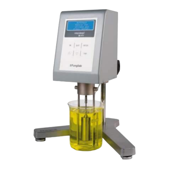
Page 10: Equipment Description
9. Equipment Description Fig. 2 Frontal view of the equipment 1. Screen 6. Temperature probe 2. Capacitive keyboard 7. Spindle 3. Nut 8. Sample container (not included) 4. Spindle guard 9. Base (viscometer support) 5. Fastening rod 10. Height adjustable knob ADVANCE Manual 10/69... - Page 11 Fig.3 Back view of the equipment Serial number label Power cable slot Warning label USB Temperature probe connector Level USB connector Power switch Thermosphere connection Fig.4. Equipment identification label Description of the equipment identification label: Viscometer model Viscometer code Serial number of the equipment Voltage and power of the equipment Electronic equipment (specifies throw in trash) ADVANCE Manual...
-
Page 12: Equipment Set-Up
9.1 Equipment set-up Remove all of the parts from the carry-case or the standard package. Note the Figure below (fig 5). Place correctly the three height adjustable knobs (B) on the Y-shaped base (A). Mount the fastening rod (C) with the holding screw (D) at the base (A). ... -
Page 13: The Keyboard And Screen
9.2 The keyboard and screen Before starting up the machine, it is recommended to become familiar with the viscometer controls seen in the previous section. The instrument has a 6 capacitive keyboard (Fig. 6) and a 4-lined Alphanumeric Display screen (Fig. 2, number 1) on the frontal part ready to use and they allow the user to interact with the machinery. -
Page 14: Menu System
10. Menu system Fungilab viscometers work with a system of menus that allow the user to go through the instrument in a quick and simple way. The basic actions in the menus are: moving through the options (‘’ and ‘’ keys), selecting an option (‘ENTER’... - Page 15 If this message appears, the technical service from the supplier or manufacturer should be contacted. To get the manufacturer’s contact information, press the <ENTER> key and the following format will appear. TECHNICAL SERVICE FUNGILAB, S.A. +34 93 685 35 00 www.fungilab.com If there is a system error, the equipment will stay blocked, meaning the motor is not working properly.
-
Page 16: Main Menu
10.3 Main Menu The main menu is the one that appears after the Autotest screen. It is accessed by turning on the machine normally and after a satisfactory result from the test run. The main menu screen will show: Instrument Setup Measurement Test profiles ↓... -
Page 17: Language
Using the ‘’ and ‘’ keys you can return to the original submenu. The main submenu provides the possibility of: Changing the working language Selecting the measurement units (viscosity and temperature) Carrying out calibrations (the machine comes calibrated from factory, therefore it is not necessary to do any calibrations when the machine is received) Adjusting the date and time. -
Page 18: Units
FUNGILAB. FUNGILAB cannot be held responsible for the measurements taken by an independently recalibrated viscometer and it is essential to follow the instructions given by Fungilab carefully when recalibrating. -
Page 19: Reset
If you do not possess this equipment, then you will not be able to guarantee good post-calibration measurements. FUNGILAB provides upon request the standard oils necessary for the calibration, as well as the accessories need to thermo-statize the oils. -
Page 20: Viscosity Calibration
Are you sure? <ENTER> <QUIT> If you press ‘ENTER’ here, the factory-stage calibration will be restored (calibration, language), the memory will be erased as well as the programming and you will return to the main configuration screen. 10.4.3.2 Viscosity calibration When selecting the viscosity option (moving through the menu with the ‘’... - Page 21 Once the spindle is in position in the device, press ‘ENTER’ again and the following screen will appear: Delay time: 00h 00m 00s In this screen it is necessary to introduce the time required from the moment you give the command to start the calibration to the moment the device begins the calibration process.
-
Page 22: Temperature Calibration
10.4.3.3 Temperature calibration Once selected the temperature option (by moving through the menu using the ‘’ and ‘’ keys) and pressed ‘ENTER’, the user will watch a screen similar to this one: Remove the Spindle and press <ENTER> VERY IMPORTANT: The Test-run should be carried out without a spindle. Once this message is shown on the screen, we should confirm that the spindle is not connected. -
Page 23: Time Settings
After a few seconds, a second screen of instructions will appear, containing the following information: Replace the 100 degree Gauge for the 200 gauge press <ENTER> Now, the PT100 simulator needs to be connected. That device generates an impedance equivalence similar to the impedance of a PT100 at 200ºC. -
Page 24: Measurement Configuration
In the second line you can see the equipment’s current date, which is presented as information only and cannot be modified. In the fourth line you can modify the date (new date). To change the date can be done by pressing ‘ENTER’ once and the whole field will be selected. Now, using the ‘’, ‘’ and ‘TAB’ keys the desired values shall be introduced. -
Page 25: Measurement Screen
Speed modification: once the corresponding field is selected using the ‘TAB' key, you can move through the pre-established speed using the ‘’ and ‘’ keys. If you want to keep the selected speed, press the ‘TAB’ key to change parameters. You have also a quicker option for changing the speed. - Page 26 In addition to visualize the obtained measurements of the sample-on-test, the user can perform other actions in parallel from this screen. Using the ‘’ and ‘’ keys, you can increase or reduce the speed of the spindle’s rotation (RPM). When pressing one of these two keys, the rotation speed increases or decreases, respectively, from the previous speed.
-
Page 27: Test Profiles
If you press the ‘ON’ key, the equipment will restart the measurements with the same configuration. 10.6 Test Profiles FUNGILAB viscometers incorporate a group of programmable logs that allow configurations to be saved in order to speed up use of the machine when carrying out measurements of a certain frequency. -
Page 28: Viscometer Programming
10.6.1.1 Viscometer programming Once the log is chosen, the following screen will appear: -- TTT & TTS -- Time to torque: Torque: 15.0% By pressing “” the next image can be seen: -- TTT & TTS -- Time to stop: Time: 00h00m00s As stated before, these abbreviations mean:... -
Page 29: Output Options
10.6.1.2 Output options By pressing the ‘ON’ key from the previous TTT and TTS configuration screen, the viscometer will show you the following screen: Status 00h 00m 00s 00h 00m 00s 00h 00m 00s Ini: record start time, ‘Beginning’ ... - Page 30 Once the log is chosen and the ‘ENTER’ key is pushed (use ‘TAB’ key to move through them), the following screen will appear. In the sample figure all of the possibilities are shown. Only one of the two words, ON/OFF, will appear depending on which function is active: ------Status------ TTT: xx.x% ON/OFF...
- Page 31 10.7 Programming The Programming menu contains the functions that allow some optional applications to be programmed for the measurements. The TTT (Time to Torque), TTS (Time to Stop) and the Speed Configuration are applications that are complementary to the normal measurements. From the main menu screen you must place the cursor “”...
-
Page 32: Options
10.8 Options The Options menu contains the information and output options that can be set in the Fungilab Viscometers. When the ‘’ cursor is on the ‘Options’ field of the main menu, you must select it by pressing ‘ENTER’. The... -
Page 33: Information
10.8.2 nformation If you select the ‘Information’ option, you will be brought to a screen in which the manufacturer contact information will be displayed, resembling this: FUNGILAB S.A. Phone:+34 93 685 35 00 Fax: +34 93 685 37 50 www.fungilab.com This option is incorporated as a means of security in the case of loss of the present document or the displacement of any reference to the company in technical support or on paper. - Page 34 If a USB-memory has been used to download the data, the viscometer will create a folder named ‘FUNGILAB’ in its root directory. The file or files resulting from the download will be stored in this folder. The first file is named ‘FDL0’ and the following ones are ‘FDL1’, ‘FDL2’ and so on. The files are saved in a CSV (Comma-Separated Values) format, so they can be opened using a plain text editor or a spreadsheet.
-
Page 35: Important Rheological Information
11. Important Rheological Information To obtain precise results it is necessary to know the most important rheological properties of the sample. Newtonian fluids The viscosity of these fluids does not depend on the shear rate meaning that at any speed the viscosity is the same. - Page 36 NOTE: The turbulent behaviour of a fluid can produce falsely high results in viscosity tests. Normally, turbulent behaviour is due to an excessively high rotation speed in relation to the viscosity of the sample (see detailed Warning further on). FACTORS AFFECTING VISCOSITY There are many variables that affect the rheological properties of products, so it is very important to take the following factors into account.
- Page 37 Examine each spindle before using it. If it’s damaged or eroded in such a way that its dimensions are changed, it will provide false results for your viscosity reading. The spindle protector (provided with every Fungilab rotational viscometer) protects the spindle and the viscometer axle and it is important for the reading of low viscosities with standard spindles.
- Page 38 The viscosity reading must be executed under laminar flow condition, not turbulent flow conditions. The first consideration is linked to the precision of the instruments. All of the FUNGILAB rotational viscometers guarantee a precision of () 1% from the bottom of any spindle/rotational speed combination scale.
- Page 39 Turbulent flow: “non-linear” flow lines. Impossible to predict the exact movement of the fluid. Very quick. For rotational systems, this means that the fluid’s movement must be circumferential. When the internal forces of a fluid end up being too great, the fluid can become a turbulent flow, in that the particles that make it up become unpredictable, making it impossible to analyse it with standard mathematical models.
-
Page 40: Accessories
12. Accessories 12.1. Low viscosity adapters (LCP and LCP/B) Low viscosity adapters (LCP y LCP/B) do not come with the standard delivery. Any of these two versions (with or without thermo station jacket) must be ordered as an additional accessory. Both LCP and LCP/B accessories are supplied complete with a spindle. -
Page 41: Mounting
**Important: The piece named G has two possible holes for the upper screw. The top hole is an universal hole to screw our low viscosity adapter to other viscometers. The bottom hole is to screw Fungilab pieces. ADVANCE Manual 41/69... -
Page 42: Dismounting And Cleaning
NOTE: Before starting with the measurements, make sure the viscometer is correctly balanced (check the bubble level). The spindle that should be selected is ‘LCP/SP’. 12.1.2 Dismounting and cleaning Unscrew the spindle of the viscometer axis and lower the spindle slowly in the sample container (K). Caution on removing the spindle, it can be hot due to a previous high temperature experiment. -
Page 43: Small Sample Adapters Apm And Apm/B
Materials: The metallic parts are made of stainless steel; the leads are made of black delrin plastic. The parts that come into contact with the sample (sample container and spindle) are made of AISI 316 and are suitable for the food industry. ... -
Page 44: Assembly
The piece named G has two possible holes for the upper screw. The top hole is a Universal hole to screw our small sample adapter to other brands viscometer. The bottom hole is to screw Fungilab pieces. NOTE: Before starting with the measurements, make sure the viscometer is correctly balanced (check it with the bubble level). -
Page 45: Dismounting And Cleaning
12. 2. 2 Dismounting and cleaning Unscrew the spindle of the viscometer axis and lower the spindle slowly in the sample container (K). Caution on removing the spindle, it can be hot due to a previous high temperature experiment. ... - Page 46 R Model or H & TR spindles Spindle Shear rate [ s ] *) Sample volume [ ml ] Container 0.93 x RPM 0.34 x RPM 10.4 TR10 0.28 x RPM 11.0 TR11 0.25 x RPM 13.5 TR12 0.48 x RPM TR12C TR13 0.40 x RPM...
-
Page 47: Heldal Unit - Helicoidal Movement Unit
Temperature range of circulation jacket and thermostatic flow conditions: Permitted temperature range: -10 a +100°C (14 a 212 °F) Use a thermostatic bath with demineralised water or refrigeration special liquid. Change the liquid from the thermostatic bath regularly. Recommended flow: 15 l/min. Materials: ... -
Page 48: Heldal Unit Mounting
12.3.1 Heldal unit mounting Fig. 16 Heldal unit set in the viscometer 1. Rib joint 9. Base 2. Lower stop ring 10. Levelling knobs 3. Displacement command 11. Heldal engine unit 4. Viscometer fastening bolt 12. Knobbed fastening rib 5. Upper stopper ring 13. - Page 49 Place the fastener (8) facing the short end of the Y-shaped base (9). Place the safety shell (1) over the fastening rib (8) on the base of the viscometer (9). Place the lower ring in the fastener (8) as explained in the sketch and fasten it with the knobbed fastening rib (12).
-
Page 50: Thermosphere
12.4. Thermosphere The Thermosphere is a heating chamber used to work with different samples at high temperatures, it allows to perform different tests with a controlled temperature. The thermosphere works in standalone mode, but it can be connected to the viscometer to send the temperature data to the viscometer screen. The Thermosphere is not included in the standard delivery. -
Page 51: Model/Spindle Correspondence Tables
13. Model/Spindle correspondence tables Standard Spindles + R1 (Table 1): Viscometer model Spindle ADVANCE L ADVANCE R ADVANCE H SPECIAL SPINDLES FOR APM ADAPTER (Table 2): Viscometer model Spindle ADVANCE L ADVANCE R TR10 TR11 TR12 TR13 ADVANCE H TR10 TR11 TR12 TR13... - Page 52 SPECIAL HELDAL SPINDLES (Table 3): Viscometer model Spindle ADVANCE L ADVANCE R ADVANCE H SPECIAL SPINDLES FOR LCP ADAPTER (Table 4): Viscometer model Spindle ADVANCE L LCP/SP ADVANCE R LCP/SP SPECIAL VANE SPINDLES (Table 5): Viscometer model Spindle ADVANCE L ADVANCE R ADVANCE H ADVANCE Manual...
-
Page 53: Model/Spindle/Oil Calibration Tables
14. Model/spindle/oil calibration tables MODEL L (Table 6): Spindle Standard oil RT50 RT500 RT500 RT1000 RT1000 RT5000 RT12500 RT50 RT500 RT500 RT1000 RT5000 MODEL R (Table 7): Spindle Standard oil RT50 RT500 RT500 RT1000 RT5000 RT5000 RT30000 RT500 RT5000 TR10 RT5000 TR11 RT5000... -
Page 54: Advance L Standard Spindle Selection Table
15. ADVANCE L standard spindle selection table Maximum guideline values in cP (mPa·s) RPM / SP 100K 400K 240K 1.2M 2.5M 200K 120K 600K 1.2M 400K 800K 300K 600K 2.4K 240K 500K 200K 400K 1.5K 7.5K 150K 300K 1.2K 120K 250K 100K 200K... -
Page 55: Advance L Special Aerial Spindle Selection Table
16. ADVANCE L Special aerial spindle selection table Maximum guideline values in cP (mPa·s) RPM / SP 100K 400K 250K 200K 125K 7.5K 2.5K 1.5K 2.5K 1.2K Table 10. ATTENTION: K Indicates thousands. Example: 7.8K = 7800 M Indicates millions Example: 1.56M = 1560000 NOTE: It is not recommended to work with viscosity values of less than 15% of the lower part of the selected scale. -
Page 56: Advance L Special Spindle Selection Table
17. ADVANCE L Special spindle selection table Maximum guideline values in cP (mPa·s) RPM / SP 100K 200K 400K 1.6M 120K 240K 100K 200K 800K 100K 500K 330K 1.5K 250K 1.2K 200K 160K 7.5K 125K 100K 2.5K 1.5K 1.2K 2.5K 1.2K Table 11. -
Page 57: Advance L Lcp Adaptor Table
18. ADVANCE L LCP Adaptor table Maximum guideline values in cP (mPa·s) RPM/SP 1.2K Table 12. ATTENTION: K Indicates thousands. Example: 7.8K = 7800 M Indicates millions Example: 1.56M = 1560000 NOTE: It is not recommended to work with viscosity values of less than 15% of the lower part of the selected scale. -
Page 58: Advance L Special Vane Spindle Selection Table
19. ADVANCE L special Vane spindle selection table Maximum guideline values in cP (mPa·s) RPM / SP 8.1K 34.6K 167K 1.6M 721K 4.9K 20.8K 100K 433K 17.3K 83.5K 848K 360K 2.4K 10.4K 50.1K 508K 216K 1.6K 6.93K 33.4K 339K 144K 1.2K 5.2K 254K... -
Page 59: Advance L Special Heldal Spindle Selection Table
20. ADVANCE L special Heldal spindle selection table Maximum guideline values in cP (mPa·s) RPM/SP 62.4K 124.8K 312K 624K 1.5M 3.1M 37.4K 74.8K 187K 374K 936K 1.8M 31.2K 62.4K 156K 312K 780K 18.72K 37.4K 93.6K 187K 468K 936K 12.4K 24.9K 62.4K 124K 312K... -
Page 60: Advance R Standard Spindle Selection Table
21. ADVANCE R standard spindle selection table Maximum guideline values in cP (mPa·s) RPM / SP 33.3K 133.3K 333.3K 666.6K 1.3M 3.33M 13.3M 200K 400K 800K 16.6K 66.6K 166.6K 333.3K 666.6K 1.6M 6.6M 100K 200K 400K 6.6K 26.6K 66.6K 133.3K 266.6K 666.6K 2.6M... -
Page 61: Advance R Special Spindle Selection Table
22. ADVANCE R Special spindle selection table Maximum guideline values in cP (mPa·s) RPM / SP TR10 TR11 TR12 TR13 166.6K 833.3K 1.6M 3.3M 1.6M 4.1M 100K 500K 2.5M 83.3K 416.6K 833.3K 1.6M 833.3K 250K 500K 500K 1.2M 33.3K 166.6K 333.3K 666.6K 333.3K... -
Page 62: Advance R Lcp Adaptor Table
23. ADVANCE R LCP Adaptor table Maximum guideline values in cP (mPa·s) 21.3K 12.8K 6.4K 4.2K 3.2K 2.5K 2.1K 1.6K 1.2K Table 17. ATTENTION: K Indicates thousands. Example: 7.8K = 7800 M Indicates millions Example: 1.56M = 1560000 NOTE: It is not recommended to work with viscosity values of less than 15% of the lower part of the selected scale. -
Page 63: Advance R Special Vane Spindle Selection Table
24. ADVANCE R special Vane spindle selection table Maximum guideline values in cP (mPa·s) RPM / SP 87.3K 370K 1.7M 18.1M 7.6M 52.3K 222K 10.8M 4.6M 43.6K 185K 891K 3.8M 26.1K 111K 535K 5.4M 2.3M 17.4K 356K 3.6M 1.5M 55.5K 267K 2.7M 1.1M... -
Page 64: Advance R Special Heldal Spindle Selection Table
25. ADVANCE R special Heldal spindle selection table Maximum guideline values in cP (mPa·s) RPM/SP 666.6K 1.3M 3.3M 6.6M 16.6M 33.3M 400K 800K 333.3K 666.6K 1.6M 3.3M 8.3M 16.6M 200K 400K 133.3K 266.6K 666.6K 1.3M 3.3M 6.6M 100K 200K 500K 2.5M 160K 400K... -
Page 65: Advance H Standard Spindle Selection Table
26. ADVANCE H standard spindle selection table Maximum guideline values in Poise RPM/SP 2.6K 10.6K 26.6K 53.3K 106.6K 266.6K 1.6K 6.4K 160K 640K 1.3K 5.3K 13.3K 26.6K 53.3K 133.3K 533.3K 3.2K 320K 533.3 2133 5.3K 10.6K 21.3K 53.3K 213.3K 1.6K 160K 1.28K 3.2K... -
Page 66: Advance H Special Spindle Selection Table
27. ADVANCE H Special spindle selection table Maximum guideline values in Poise RPM / SP TR10 TR11 TR12 TR13 13.6K 66.6K 133.3K 266.6K 133.3K 333.3K 160k 200K 6.6K 33.3K 66.6K 133.3K 66.6K 166.6K 100K 2.6K 13.3K 26.6K 53.3K 26.6K 66.6K 1.6K 1.3K 6.6K... -
Page 67: Advance H Special Vane Spindle Selection Table
28. ADVANCE H special Vane spindle selection table Maximum guideline values in poise RPM / SP 6.9K 29.6K 142K 1.4M 615K 4.1K 17.7K 85.6K 868K 369K 3.4K 14.8K 71.3K 724K 307K 8.8K 42.8K 434K 184K 1.3K 5.9K 28.5K 289K 123K 4.4K 21.4K 217K... -
Page 68: Advance H Special Heldal Spindle Selection Table
29. ADVANCE H special Heldal spindle selection table Maximum guideline values in Poise RPM/SP 53.3K 106K 266.6K 533.3K 1.3M 2.6M 160K 320K 800K 1.6M 26.6K 53.3K 133.3K 266.6K 666.6K 1.3M 160K 400K 800K 10.6K 21.3K 53.3K 106K 266.6K 533.3K 200K 400K 6.4K 12.8K... -
Page 69: Warranty Certificate
When the serial number is incorrect or it does not suit with the written in the warranty. FUNGILAB’s sole obligation shall be to repair or to replace any part(s) that prove defective within the warranty period and shall not be liable for consequential damages resulting from the use of its...
Need help?
Do you have a question about the VISCOLED ADVANCE Series and is the answer not in the manual?
Questions and answers