Table of Contents
Advertisement
Quick Links
Advertisement
Table of Contents
Troubleshooting

Subscribe to Our Youtube Channel
Summary of Contents for SM ALFOplus2
- Page 1 ALFOplus2 Access Link Full Outdoor User manual MN.00356.E - 003...
- Page 2 The information contained in this handbook is subject to change without notice. Property of Siae Microelettronica. All rights reserved according to the law and according to the international regulations. No part of this document may be reproduced or transmitted in any form or by any means, electronic or mechanical, without written permission from Siae Microelettronica S.p.A.
-
Page 3: Table Of Contents
SYSTEM PRESENTATION ..................15 GENERAL......................15 CHARACTERISTICS ...................15 APPLICATIONS ....................16 5.3.1 ALFOplus2 connectivity ................16 5.3.2 Universal product line architecture and single SM-OS ........16 ALFOPLUS2 STRUCTURE ..................17 LINK CONFIGURATION ..................17 5.5.1 Single ALFOplus2 ..................18 5.5.2 Dual ALFOplus2 ..................18 ANTENNAS AND EXTERNAL BRANCHING ..............20... - Page 4 POWER SUPPLY AND CABLE ................36 PHYSICAL DIMENSIONS ..................36 SURGE AND LIGHTNING PROTECTION ..............38 ENVIRONMENTAL CONDITIONS ................38 Section 3. INSTALLATION INSTALLATION OF ALFOplus2 ..................39 GENERAL INFORMATION TO BE READ BEFORE THE INSTALLATION......39 GENERAL......................40 ELECTRICAL WIRING..................40 CONNECTIONS TO THE SUPPLY MAINS ..............40 GROUNDING CONNECTION ................41 7.5.1 Mounting instruction of grounding cable KIT ICD00072F (Universal, No tools) .41...
- Page 5 ACCESSORIES FOR INSTALLATION ..............59 7.13.1 Installation procedure of optical junction ............62 7.13.2 Installation procedure of Rosenberger outdoor enclosure......62 Section 4. LINE-UP LINE-UP OF ALFOplus2 ....................65 GENERAL......................65 SWITCH ON .....................65 ALARM LED CHECK ...................66 CONNECTION PROCEDURE.................66 8.4.1 WEBLCT via MNGT port (cable F03616) ............66 8.4.2 CLI session via MNGT or console port ............67...
- Page 6 11.9 OPTIMIZING ANTENNA ALIGNMENT WITH RX MEASUREMENT ........82 12 ETHERNET TRAFFIC CONFIGURATION..............84 12.1 GENERAL......................84 12.2 CB EXAMPLE ....................85 12.2.1 CB example configuration by WEBLCT............85 12.2.2 CB example configuration by WEBLCT: PORT STATUS ........85 12.2.3 CB example configuration by WEBLCT: TRAFFIC VLAN CREATION ....86 12.2.4 CB example configuration by WEBLCT: PORT SETTINGS .......86 12.2.5 CB example configuration by CLI...............87 12.2.6 PCB example ..................88...
- Page 7 15.2 SUPERVISION ....................107 15.2.1 General ....................108 15.2.2 ALFOplus2 - 1NE - InBand..............108 15.2.3 ALFOplus2 - On-Site Management Port (MNG) .......... 109 15.2.4 Address ....................109 15.2.5 Console access mode ................110 15.3 COMPILING SCRIPT USING COMMAND RUN............110 Section 7.
- Page 8 19 ALFOplus2 18 GHZ CHARACTERISTICS..............127 19.1 FOREWORD ....................127 19.2 AVAILABLE FREQUENCIES ................127 19.2.1 Transmitter characteristics ..............130 19.2.2 Receiver characteristics ................. 131 19.3 RADIO FLANGE....................132 19.4 POWER SUPPLY AND CONSUMPTION ..............132 20 ALFOplus2 23 GHZ CHARACTERISTICS..............133 20.1...
-
Page 9: User Guide
Via Buonarroti, 21 - Cologno (MI) - Italy DECLARES THAT THE PRODUCT Digital Radio Relay System ALFOplus2 complies with the essential requirements of article 3 of the R&TTE Directive (1999/05/EC) and therefore is marked: The following standards have been applied: EN 60950-1:2006 and EN 60950-22:2006 “Safety of information technology equipment”... -
Page 10: First Aid For Electrical Shock And Safety Rules
FIRST AID FOR ELECTRICAL SHOCK AND SAFETY RULES FIRST AID FOR ELECTRICAL SHOCK Do not touch the bare hands until the circuit has been opened. pen the circuit by switching off the line switches. If that is not possible protect yourself with dry material and free the patient from the con- ductor. -
Page 11: Safety Rules
Tab.1 - Artificial respiration Step Description Figure Lay the patient on his back with his arms parallel to the body. If the patient is laying on an inclined plane, make sure that his stomach is slightly lower than his chest. Open the patients mouth and check that there is no foreign matter in mouth (den- tures, chewing gum, etc.). - Page 12 Fig.1 - Components electrostatic charge sensitive indication In order to prevent the units from being damaged while handling, it is advisable to wear an elasticised band (Fig.2) around the wrist ground connected through coiled cord (Fig.3). Fig.2 - Elasticized band Fig.3 - Coiled cord This device has Class I LASER modules: it is not required to have a laser warning label or other laser state- ment (IEC 60825-1).
-
Page 13: Correct Disposal Of This Product (Waste Electrical & Electronic Equipment)
CORRECT DISPOSAL OF THIS PRODUCT (WASTE ELECTRICAL & ELECTRONIC EQUIPMENT) (Applicable in the European Union and other European countries with separate collection systems). This marking of Fig.4 shown on the product or its literature, indicates that it should not be disposed with other household wastes at the end of its working life. -
Page 14: Purpose And Structure Of The Manual
PURPOSE AND STRUCTURE OF THE MANUAL PURPOSE OF THE MANUAL The purpose of this manual consists in providing for the user information which permit to operate and maintain the ALFOplus radio equipment. This manual does not include information relevant to the SCT/WebLCT management program Warning: windows and relevant application. -
Page 15: Descriptions And Specification
Section 2. DESCRIPTIONS AND SPECIFICATION LIST OF ACRONYMS LIST OF ACRONYMS What follows is a list of acronyms used in this handbook: Adaptive Code Modulation Data Communication Network DSCP Differentiated Serviced Code Point Ethernet Forward Error Correction Indoor Unit Line of Sight IPV4 –... - Page 16 Quality of Service Subnetwork Craft Terminal SNMP Simple Network Management Protocol MIMO Multiple Input Multiple Output Telecommunication Management Network ToS/QoS Type/Quality of Service VLAN Virtual Local Area Network. MN.00356.E - 003...
-
Page 17: System Presentation
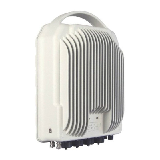
This document contains the description of features and capability of ALFOplus2 equipment. ALFOplus2 (see Fig.5) is a Full Outdoor microwave radio that houses, within a unique unit, two complete TX/RX radio channels (RF Multi-core definition) to double the radio capacity and includes a complete Carrier Ethernet features set. -
Page 18: Applications
• emergency wireless links • zero footprint applications ALFOplus2 doesn’t need any indoor unit and the power supply can be provided directly by POE through the data cable or through a dedicated auxiliary port. 5.3.1 ALFOplus2 connectivity ALFOplus2 offers 4xGbE traffic ports (see Fig.6): •... -
Page 19: Alfoplus2 Structure
• SM-OS software, based on carrier-grade field proven highly interoperable protocol stack provides complete MPLS services set and compliancy to CE2.0. ALFOplus2 has been developed with this concept in mind: Unified Hardware and Software platform archi- tecture ALFOPLUS2 STRUCTURE ALFOplus2 mechanical structure is made up by a main body and three possible additional antenna-interface modules, lodged in the reserved bay (see Fig.7). -
Page 20: Single Alfoplus2
• 2+2 XPIC (HSTBY or FD) • 4+0 CP unprotected • 4+0 AP unprotected • 4+0 XPIC unprotected. Tab.3 - Dual ALFOplus2 in 2+0 configurations (purpose, interface module, used antenna) Dual ALFOplus2 Antenna type 2+0 operations Interface Circular Dual module... - Page 21 Hybrid 2+2 AP protected FD 2 ports Hybrid 2+2 XPIC protected FD 2 ports Hybrid Tab.4 - Dual ALFOplus2 in 4+0 configurations (purpose, interface modules, used antenna) Dual units Antenna type 4+0 operations Interface Circular Dual module Single waveguide Radio...
-
Page 22: Antennas And External Branching
ANTENNAS AND EXTERNAL BRANCHING The previous Link configuration can be pointed out depending antenna and eventual external branching. 5.6.1 SINGLE ODU The following configuration can be obtained by a single polarization antenna: 1+0, 2+0 CP. The following configuration can be obtained with a double polarization antenna: 2+0 AP, 2+0 XPIC. See Fig.8. -
Page 23: Dual Odus, 2 Hybrid And Dp Antenna
5.6.3 Dual ODUs, 2 hybrid and DP antenna The following configurations can be obtained by a DP antenna, not integrated, and 2 hybrids as in Fig.10: 2+2 AP SW/HSBY prot, 2+2 XPIC SW/HSBY prot, 2+2 XPIC FD prot, 4+0 XPIC. Fig.10 - Configuration with 2 external hybrids and a not integrated DP antenna 5.6.4 Dual ODUs and DP antenna... -
Page 24: Radio Functionalities
Fig.11 - Configuration with a not integrated DP antenna RADIO FUNCTIONALITIES The functionalities implemented in ALFOplus2 are the following: • up to 4Gbps guaranteed radio throughput • software activated Dual carrier RF multi-core • 4QAM-4096QAM ACM with different FEC rate codes •... -
Page 25: Acm
• InBand/OutOfBand management • Power over Ethernet or dedicated power feeders • full featured future proof CE switch • future proofs unified architecture and OS software platform. 5.7.1 SIAE MICROELETTRONICA implements MSE based Adaptive Coding and Modulation in all channel band- widths. -
Page 26: Rf Band/High Power Versions
5.7.2 RF band/High Power versions ALFOplus2 is available in several RF band with various Tx/Rx spacing and two Tx Power profiles, standard and High Power. • Standard power: 18 GHz 23 GHz 25 GHz 28 GHz 38 GHz 42 GHz •... -
Page 27: Ingress Port Rate Limiting (Storm Control)
• MAB: MW adaptive bandwidth by OAM message support (feature jointly developed with Cisco) • 2.5Gbps GbE Ports for cable saving installation. 5.8.1 Ingress port rate limiting (Storm control) Storm control limits the maximum amount of traffic that can be accepted at the input of the switch LAN ports: it’s possible to apply, for each LAN port, a rate limiter (PIRL set as active for each relevant LAN in- terface) to a combination of incoming traffic types (independently from the VLAN ID and priority level). -
Page 28: Classification Criteria
Fig.12 - QoS example 5.8.5 Ingress Filter Policing ALFOPLUS2 allows limiting the ingress traffic rate on the basis of: • UNI Port Based (Bandwidth profile per UNI port): a different profile is defined for each LAN port (VLAN ID and priority are not considered in this case by the rate limiting algorithm) •... -
Page 29: Queues And Congestion Avoidance Methods
WRR - the available bandwidth is shared among the different priorities with configurable weights It is also possible to configure at the same time some queues as Strict Priority and the remaining as WRR. ALFOPLUS2 ethernet switch supports 8 queues per port with configurable depth. MN.00356.E - 003... -
Page 30: Egress Shaping
The egress VLAN can be removed on the basis of the following criteria: • Port Based • Port and C-tag based. SECURITY Following security protocols are implemented in ALFOplus2: • SNMP V3 • security management (SSH, SFTP) • secure HTTP access (HTTPS) •... -
Page 31: Management
5.10 MANAGEMENT ALFOplus2 unit can be monitored via GE interfaces and via serial connector. Management can be InBand or OutOfBand Unit management level is in line with all the other SIAE MICROELETTRONICA products: • configurations via SNMP v.1/v.2/v.3 datagram •... -
Page 32: Technical Specification
RF frequency. ADAPTIVE MODULATION ALFOplus2 implements an adaptive modulation algorithm to improve the system gain when the quality of the received signal become insufficient to guarantee an error free link. Adaptive modulation guarantees error free and hitless unidirectional downshifts with fading speed up to 30 dB/s. -
Page 33: Ethernet Electrical Interface Characteristics
RXdem µP data, prot. protocol Cntr Ch ACM/ATPC To/From other ODU Fig.14 - ALFOplus2 blocks diagram 6.2.1 Ethernet electrical interface characteristics RJ45 interfaces have lightining protection. Gigabit electrical Ethernet connector6 LAN3 RJ45 10/100/1000BaseT LAN4 RJ45 10/100/1000BaseT Ethernet cable category... - Page 34 0.384 0.315 0.297 0.283 0.278 0.276 0.272 0.272 0.269 0.266 0.378 0.297 0.289 0.281 0.271 0.269 0.263 0.262 0.262 0.259 0.282 0.246 0.234 0.224 0.221 0.215 0.213 0.211 0.210 0.208 0.217 0.185 0.181 0.177 0.172 0.169 0.169 0.168 0.167 0.166 One way delay (msec) Physical modes (128 bytes) Channel size (MHz)
- Page 35 0.326 0.255 0.247 0.233 0.231 0.226 0.222 0.219 0.219 0.218 0.241 0.205 0.190 0.187 0.182 0.179 0.176 0.175 0.174 0.173 One way delay (msec) Physical modes (1024 bytes) Channel size (MHz) 4QAM 16QAM 32QAM 64QAM 128QAM 256QAM 512QAM 1K QAM 2K QAM 4K QAM 1.522...
-
Page 36: Ethernet Optical Interface Characteristics
One way delay (msec) Physical modes (4000 bytes) Channel size (MHz) 4QAM 16QAM 32QAM 64QAM 128QAM 256QAM 512QAM 1K QAM 2K QAM 4K QAM 1.609 1.394 1.239 1.101 1.021 0.960 0.922 0.904 0.869 2.789 1.206 1.038 0.909 0.831 0.770 0.728 0.712 0.691 0.667... -
Page 37: Loops
Gigabit 2.5 Gbps Parameter Multi Mode Multi Mode 50/125 m 62.5/125 m 50 m 62.5/125 m Receive sensitivity -17 dBm -22 dBm Average receive power max 0 dBm 0 dBm Compliance 1000BaseSX 2500BaseX IEEE 802.3z IEEE 802.3z Transceiver type Pluggable Connector type LOOPS To check the correct operation a set of local and remote loops are made available. -
Page 38: Power Supply And Cable
M10184 (2.5mmq) 100.00 250.00 An adapter is required PHYSICAL DIMENSIONS ALFOplus2 physical dimensions include Hybrid or OMT module. See Fig.16: wxhxd 252mm x 363mm x 148mm (frequency 15GHz) 252mm x 363mm x 176mm (frequency < 15 GHz) Unit Weight 8Kg (frequency 15GHz) 11.5Kg (frequency <... - Page 39 Fig.16 MN.00356.E - 003...
-
Page 40: Surge And Lightning Protection
SURGE AND LIGHTNING PROTECTION Protection Method Gas dischargers: in accordance to EN 301 489 and IEC 61000-4-5 Class4 ENVIRONMENTAL CONDITIONS Operational temperature range -33°C ÷ +55°C Temperature range of degraded performances -40°C ÷ +60°C Environmental conditions and environmental tests ETSI EN 300 019 Class 4.1 Class 1.2 Storage, Class 2.3 Transportation Operational humidity Weather proof according to IP65... -
Page 41: Installation
SIAE disclaims any liability or responsibility for the results of improper or unsafe installation practices. ALFOplus2 equipment is a full-outdoor IP Ethernet radio link system operating in various band frequency RF bands coverage up to 42 GHz for transport capacity up to 2036 Mbit/s, designed to establish LAN-LAN connections. -
Page 42: General
Position and pin-out of the equipment connectors are available in this section. CONNECTIONS TO THE SUPPLY MAINS During the final installation, protect the ALFOplus2 by a magneto-thermal switch (not supplied with the equipment), whose characteristics must comply with the laws in force in one’s country. -
Page 43: Grounding Connection
1. Ethernet Switch chassis grounding point. The cross section area of the cable used must be 4 sq. 2. ODU (ALFOplus2) grounding M6 bolt copper faston type. The cross section area of the cable used must be 16 sq. mm 3. - Page 44 Tab.9 - Mounting Instructions Description Remove the cable jacket by 30mm width approximate- Take care not to damage the copper conductor. Clean and dry the application area. Remove the protective film from the butyle sealing paste. Put the contact in position on the cable, by firmly press- ing on the cable jacket, checking the adherence of the butyle sealing paste.
-
Page 45: Required Tools For Mounting (Not Supplied)
INSTALLATION PROCEDURE The installation sequence is the following: • ODU assembling: the proper antenna interface module is installed over the ALFOplus2 • Installation of the ODU: Single output flange - installation of the ODU over the antenna by means of the standard mount-... - Page 46 Groove for ODU gasket External side Internal side Fig.18 – Antenna adapter module (left: external side - right: internal side) Protruding ODU gasket Fig.19 – ODU cavity MN.00356.E - 003...
-
Page 47: Odu Installation - Single Rectangular Output Flange
ODU INSTALLATION – SINGLE RECTANGULAR OUTPUT FLANGE In this case the standard mounting flange (Z21823) is used (see Fig.20). Use centring ring and relevant screws and the 4 M10 bolts to install the mounting flange on the ALFOplus2. M10 screws Z21823 flange Fig.20 –... -
Page 48: Odu Installation - Omt Output Flange
Only for OMT ALFOplus2 the mounting flange is the Z22011 with closed slot in upper position according to the position of the pole (see Fig.22). Use centring ring and relevant screws and the 4 M10 bolts to install the mounting flange on the ALFOplus2. MN.00356.E - 003... - Page 49 Z22011 flange M10 screws Fig.22 – ALFOplus with Standard mounting flange Install the antenna using the antenna installation guide (specific for each antenna) inside the antenna box provided by antenna producer. Keep attention to the position of the antenna feeder depending on request- ed setting.
-
Page 50: Odu Installation - Dual Output Flange
5) through the six mounting holes (see Fig.26). When all the bolts are positioned, tight- en them (use 15mm spanner, torque=46mm) • from the two RF flanges of ALFOplus2 two wave guides are necessary to connect them to the an- tennas as in Fig.27. MN.00356.E - 003... - Page 51 Tooth ALFOplus2 mounting holes Fig.24 – Pole mounting of dual flanges ALFOplus2 MN.00356.E - 003...
- Page 52 ALFOplus2 mounting holes Fig.25 – Mounting holes MN.00356.E - 003...
- Page 53 Fig.26 - Installation of dual flanges ALFOplus2 MN.00356.E - 003...
- Page 54 Fig.27 - Dual flanges ALFOplus2 with waveguides connected to the two RF flanges MN.00356.E - 003...
-
Page 55: User Connectors
7.12 USER CONNECTORS ALFOplus2 provides 2xM12 5pin connector and 4 Ethernet ports as shown in Fig.36. The Ethernet ports are: • 2 LAN SFP (1 Gbps or 2.5 Gbps) Optic Rosenberger connectors: LAN1 and LAN2 • 2 LAN RJ45 (1 Gbps) Electric Rosenberger connectors, with surge arrester: LAN3 and LAN4. - Page 56 • The interface has lightning protection. Tab.11 - Pinout MNGT connector Pinout Description Vpointing (+) Shield Vpointing (-) MN.00356.E - 003...
- Page 57 Fig.28 - F03594 cable for lab use only ALFOplus2 don’t use connectors 8 and 4 of F03594. Protect them. Warning: MN.00356.E - 003...
- Page 58 Fig.29 - F03616 maintenance cable (to remove after commission pointing) MN.00356.E - 003...
- Page 59 Fig.30 - F03622 console cable (remove it after use) MN.00356.E - 003...
-
Page 60: Rj45 Connector
7.12.2 RJ45 connector The electrical RJ45 connection to ALFOplus2 is guaranteed only with coded connector. Part to be assembled (see Tab.12). Tab.12 - Part to be assembled SIAE code Description View Data cable SF/UTP CAT5e for outdoor M02472 (AWG24) 100 Ohm... -
Page 61: Accessories For Installation
Assignment T568A T568B 1000Base-T Colour wire Colour wire BI_DD+ WHT/BRN WHT/BRN BI_DD- Straight cable EIA/TIA-568B Fig.31 - Straight Ethernet cable Fig.32 - RJ-45 Pinout Fig.33 - Indoor RJ45 unshielded assembly 7.13 ACCESSORIES FOR INSTALLATION In the following a list of materials to be used during installation. MN.00356.E - 003... - Page 62 Tab.14 - Accessories for installation SIAE code Descriptions View Junction optical box IP66, for fallen of a. b. U00900 optical cable to connect 1 ODU Fibre optical junction optical box for 1 U00921 Junction box IP66, for fallen of optical a.
- Page 63 SIAE code Descriptions View Rosenberger outdoor enclosure P20101 (for LC fiber and RJ45 LAN cable) The boxes do not foresee replacement seal. If the second ODU connection takes place much later than the first one, it is possible that the closing of U00922 box doesn’t guarantee the seal tightness.
-
Page 64: Installation Procedure Of Optical Junction
7.13.1 Installation procedure of optical junction Components Fig.34 - Components 7.13.2 Installation procedure of Rosenberger outdoor enclosure The kit P20101 Rosenberger outdoor enclosure is an universal outdoor connector used for LC fiber and RJ45 LAN cable. Follow the graphical passages in Fig.35 for fiber assembly, the same procedure can be used for RJ45 LAN outdoor cable. - Page 65 Fig.35 - P20101 assembly procedure MN.00356.E - 003...
- Page 66 MN.00356.E - 003...
-
Page 67: Line-Up
Section 4. LINE-UP LINE-UP OF ALFOPLUS2 GENERAL The line-up consists of the following steps: • switch on equipment • alarm leds check • connection procedure • equipment configuration (through PC software) • optimizing antenna orientation • check of Ethernet connections •... -
Page 68: Alarm Led Check
MAINTENANCE. CONNECTION PROCEDURE ALFOplus2 line-up can be done via MNGT (Gi 0/4) port using WEBLCT or Hyperterminal and via console port using Hyperterminal only. LAN1 and LAN2 are disabled by default. The factory default IP addresses are 172.20.254.14/16 ODU L and 172.20.255.15/16 ODU H. -
Page 69: Cli Session Via Mngt Or Console Port
• write password: admin • click Login button. PC and ALFOplus2 must be in the same subnet. Warning: Fig.37 - Login window 8.4.2 CLI session via MNGT or console port Open a hyperterminal session via MNGT port (cable F03616): •... - Page 70 • type show nvram to know the actual IP address Fig.38 - Hyperterminal login and result of “show nvram” command MN.00356.E - 003...
-
Page 71: Bridge Mode (Weblct And Cli)
In WEBLCT select Base Band menu, Ethernet, Bridge Mode Conf.: • Select the Bridge Mode: Customer Bridge • Click Apply and Confirm ...the ALFOplus2 restarts automatically (traffic affecting). V ia W E B LC T V ia C LI Command Purpose #Enable Customer Bridge (802.1q) -
Page 72: Management: Out Of Band/In Band
Traffic ports – LAN1, LAN2, LAN3 and LAN4 Management ports – LAN1, LAN2, LAN3, LAN4 and MNGT (VLAN127 in the example). LAN1 Gi 0/7 Optical 1/2.5G LAN2 Gi 0/9 Optical 1/2.5G ALFOplus2 LAN3 Gi 0/3 Gi 0/6 Electrical 1G 2.5G LAN4 Gi 0/5... -
Page 73: Out Of Band: Mngt Vlan Creation (Weblct)
Remote Element List Restart • MNGT VLAN creation (Vid=1), IP address, Agent IP Address and default gateway. 10.2.1 Out of band: MNGT VLAN creation (WEBLCT) For the Out of band example, involved ports are: MNGT, LAN2 and TRX. Among them MNGT and LAN2 are untagged. -
Page 74: Out Of Band: Setting The Agent Ip (Weblct)
10.2.3 Out of band: Setting the Agent IP (WEBLCT) In WEBLCT select Equipment Properties, General Info Card. • Write Agent IP Address (copy from IP Address below) • Click Apply and confirm. Fig.43 - Agent IP setting 10.2.4 Out of band - Remote Element List (WEBLCT) Into WebLCT at right position: •... -
Page 75: Out Of Band - Restart
Press the button System Restart and Confirm. 10.2.6 Out of band: IP Address, MNGT VLAN, Agent IP and Default Gate- way (CLI) This is the CLI script for the setup of Out of Band Management. Add the script after SM-OS#. #Customer bridge bridge-mode customer #set MTU=2048byte... -
Page 76: In Band Management
default gateway route 192.168.79.1 #Configure management interfaces interface gigabitethernet 0/4; switchport priority default 7; switchport ingress-filter; no shutdown exit interface gigabitethernet 0/9; switchport pvid 1; switchport priority default 7; switchport ingress-filter; no shutdown exit interface gigabitethernet 0/3 shutdown; no negotiation; speed 2500; no shutdown reload. -
Page 77: In Band: Ip Address (Weblct)
Write Agent IP Address (copy from IP Address below) • Click Apply and confirm • If MNGT port address and MNGT VLAN have been already set, it’s time to restart the ALFOplus2: click System Restart and confirm. MN.00356.E - 003... -
Page 78: In Band: Remote Element List (Weblct)
Fig.47 - Agent IP setting 10.3.4 In band: Remote element list (WEBLCT) Into WebLCT at right position: • press the button to expand Remote Element List window • Clear and Apply new list • add station, type “SIAE LINK” and press OK •... -
Page 79: In Band: Ip Address, Mngt Vlan, Agent Ip And Default Gateway (Cli)
10.3.6 In band: IP Address, MNGT VLAN, Agent IP and Default Gateway (CLI) This is the CLI script for the setup of In Band Management. Add the script after SM-OS#. #Customer bridge bridge-mode customer #Set MTU=2048byte System MTU 2048 #add VLAN 127... -
Page 80: Radio Link Line-Up
RADIO LINK LINE-UP 11.1 GENERAL The radio link setup is made up by: • radio configurator • modulation & capacity setting • link ID setting • frequency setting • Tx power setting (no ATPC) • Tx power setting (ATPC) All these operations are achieved via WEBLCT. In following paragraphs these operations are explained. 11.2 RADIO CONFIGURATOR In WEBLCT select Equipment menu, Radio Configurator. -
Page 81: Modulation & Capacity
Fig.48- New link 11.3 MODULATION & CAPACITY In WEBLCT select Equipment menu, BW & Mod./Link ID. In Modulation & Capacity card, the following parameters must be set: • ACM Engine Disabled (single modul. Profile) set Bandwidth: 14, 20, 28, 30, 40, 50, 56, 60, 80 or 112 MHz set Ref Modul ...that is the used one: 4, 16, 32, 64, 128, 256, 512, 1024, 2048 or 4096QAM click Apply and Confirm •... -
Page 82: Modulation & Capacity Parameters
11.4 MODULATION & CAPACITY PARAMETERS • Modulation profiles 4, 16, 32, 64, 128, 256, 512, 1024, 2048 and 4096QAM 4QAM and 16QAM have the strong version also; the modulation is the same but the payload in the strong case is lower because of a bigger over- head (stronger protection code). -
Page 83: Odu Powers (No Atpc)
• in field Measurements Resolution select the resolution of Tx and Rx power reading No manual operations must be active on the radio. • click Apply and Confirm. Fig.51 - Tx frequency setting and measurement resolution On remote IDU Tx and Rx frequencies are the opposite respect the local. Note: 11.7 ODU POWERS (NO ATPC) -
Page 84: Optimizing Antenna Alignment With Rx Measurement
1(A) through a voltmeter connected to MNGT port on the ODU (F03616 cable - see Fig.29). In order to get the Rx signal power level via software, connect the PC to ALFOplus2 and start the WebLCT. Into WebLCT is shown in the top status bar (Rx1A= -value dBm) see Fig.44:... - Page 85 If you’re using a voltmeter the Rx signal power level is available on the MNGT port of ODU, the measure- ment can be performed with a proper cable (see Fig.29). Following this last procedure, the voltage you’re reading with the voltmeter is proportional to Rx power level, refer to Tab.15. Tab.15 - Voltage measured in 48V port Error [dB] @ Received Signal [dBm]...
-
Page 86: Ethernet Traffic Configuration
ETHERNET TRAFFIC CONFIGURATION 12.1 GENERAL Some examples of traffic port configuration are suggested in the following paragraphs using two ports only, LAN1 and LAN2 on local and remote unit. Other ports can be used following the same procedures here shown. Three main configurations “pipe”... -
Page 87: Cb Example
12.2 CB EXAMPLE Units in Customer Bridge mode: the transmitted traffic is untagged and/or known C-tagged. U ntag g ed traffic C -tag g ed ≠ Vid10, Vid 20 D ropped C 10-p2 Know n C -tag g ed (VID and p) S -tag g ed traffic Def VID=101 Def VID=101... -
Page 88: Cb Example Configuration By Weblct: Traffic Vlan Creation
Bridge Port Type Customer Bridge • push Apply and confirm. Fig.56 - Port status 12.2.3 CB example configuration by WEBLCT: TRAFFIC VLAN CREATION In WEBLCT select Base Band menu, Ethernet and VLAN: • select Static VLANs card and click Add: Static VLAN Configuration window is open •... -
Page 89: Cb Example Configuration By Cli
SM-OS(config-vlan)# ports gigabitethernet 0/3 gigabitethernet 0/7 untagged gigabitethernet 0/7 name Vlan101 SM-OS(config-vlan)# exit SM-OS(config)# interface gigabitethernet 0/7 SM-OS(config-if)# shutdown; switchport pvid 101; switchport priority default 6; switchport ingress-filter; mtu 2048; negotiation; no shutdown SM-OS(config-if)# exit SM-OS(config)# vlan 10 SM-OS(config-vlan)# ports gigabitethernet 0/7 gigabitethernet 0/3 name Vlan10... -
Page 90: Pcb Example
SM-OS(config)# interface gigabitethernet 0/3 SM-OS(config-if)# shutdown; switchport ingress-filter; mtu 2048; no negotiation; speed 2500; no shut- down SM-OS(config-if)# exit 12.2.6 PCB example Units in Provider Core Bridge mode (Provider Bridge 802.1ad): the transmitted traffic is known S-tagged only. S 101 S -tag g ed ≠... -
Page 91: Pcb Example Configuration By Weblct: Traffic Vlan Creation
• set the following parameters: Admin State enabled Auto Neg. selected or not MDI/MDIX auto 46Byte up to 12266Byte (can be done with port disabled only) Bridge Port Type provider network • push Apply and confirm. Fig.60 - PB Port status 12.2.9 PCB example configuration by WEBLCT: TRAFFIC VLAN CREATION In WEBLCT select Base Band menu, Ethernet and VLAN... -
Page 92: 11Pcb Example Configuration By Cli
SM-OS(config-vlan)# ports gigabitethernet 0/3 gigabitethernet 0/9 name Vlan102 SM-OS(config-vlan)# exit SM-OS(config)# interface gigabitethernet 0/9 SM-OS(config-if)# shutdown; switchport ingress-filter; mtu 2048; negotiation; no shutdown SM-OS(config-if)# exit SM-OS(config)# interface gigabitethernet 0/3 SM-OS(config-if)# shutdown; switchport ingress-filter; mtu 2048; no negotiation; speed 2500; no shut- down SM-OS(config-if)# exit MN.00356.E - 003... -
Page 93: Peb Example
12.3 PEB EXAMPLE Units in Provider Edge Bridge mode. The transmitted traffic is untagged and/or unknown C-tagged. U ntag g ed traffic S -tag g ed traffic D ropped U nk now n C -tag g ed (VID and p) 10 -p2 Def VID=101 Def VID=101... -
Page 94: Peb Example Configuration By Weblct: Traffic Vlan Creation
Auto Neg. selected or not MDI/MDIX Auto 46Byte up to 12266Byte (can be done with port disabled only) Bridge Port Type Customer Network (port-based) • push Apply and confirm. Fig.64 - PEB Port status 12.3.3 PEB example configuration by WEBLCT: TRAFFIC VLAN CREATION In WEBLCT select Base Band menu, Ethernet and VLAN •... -
Page 95: Peb Example Configuration By Cli
6; switchport pvid 102; switchport priority default 6; switchport ingress-filter; mtu 2048; nego- tiation; no shutdown SM-OS(config-if)# exit SM-OS(config)# interface gigabitethernet 0/3 SM-OS(config-if)# shutdown; switchport ingress-filter; mtu 2048; no negotiation; speed 2500; no shut- down SM-OS(config-if)# exit. MN.00356.E - 003... -
Page 96: Commissioning Measures For Ethernet Traffic
Scope Scope of this paragraph is to provide a procedure that describes, step by step, how to perform the software upgrade of ALFOplus2 equipment. Downloading time depends on connection used between PC and ALFOplus2. In order to transfer data, “WebLCT Console” running is necessary. - Page 97 System Version Download 1. Unzip files N50052 XXX.zip in a suitable directory of the PC used to performed the upgrade. 2. Connect to the equipment using the WebLCT (login as “Admin”) 3. Open the Software Download window: using WebLCT select Software Info&Maint (see Fig.67) from Equipment Menu and press Upgrade (see Fig.68) 4.
-
Page 98: Backup Configuration
Fig.68 - Upgrade software 12.6 BACKUP CONFIGURATION 12.6.1 Scope This chapter describes the procedure to backup the configuration. In order to transfer data, “WebLCT console” running is necessary. Warning: 12.6.2 Backup/restore configuration using WEBLCT Backup Configuration It is advisable to backup the configuration after the first installation. Proceed as follows: Foreword: 1. - Page 99 3. Push Restore. The status of the backup procedure is shown in the “operation Status” field. During Restore operation the equipment creates a backup configuration, you can come back to this config- uration at the end of the restore pushing Revert (see Fig.69). Fig.69 - Backup/Restore configuration MN.00356.E - 003...
- Page 100 MN.00356.E - 003...
-
Page 101: Maintenance
Section 5. MAINTENANCE ALARMS 13.1 GENERAL In this document a description of alarms is present, in order to help operators to perform equipment trou- bleshooting. 13.2 ALARMS SYSTEM There are two way to detect alarms: • through LEDs • through WebLCT For each part of the units, groups of alarms are defined. -
Page 102: Led Status
13.2.1 LED status ALFOplus2 has 2 LEDs on frontal side of the case (see Fig.70). Radio B Radio A Fig.70 - ALFOplus2 alarm LEDs The LEDs can be red or green. Information provided, relevant radio A or radio B, are: •... - Page 103 Tab.16 - Alarm severity list Class WebLCT name Description Default severity COMMON Equip Manual Operation At least one manual operation active Warning ETH LAN Eth Lan Phy Link Loss Loss of Ethernet signal Major PM ACM - 24H Alarm Major ACM measurements on received radio P.M.
- Page 104 Class WebLCT name Description Default severity Timing Sync Active Status Timing Sync is active Status Timing Sync Drift Alarm Selected Synch bad quality Major Timing Sync Los Alarm Selected Synch missing Major SETS Timing Generator Holdover Status Equipment in holdover status Warning Timing Generator Free Running Equipment in Free Running status...
-
Page 105: Maintenance And Troubleshooting
Rx field (value measured must comply with that resulting from hop calculation) • S/N (presence of possible interference) • BER (values measured must comply with hop calculations) How these operations are carried out is specified in “Line–up” section or, more widely, in ALFOplus2 man- ual. MN.00356.E - 003... -
Page 106: Corrective Maintenance (Troubleshooting)
14.2.2 Corrective maintenance (troubleshooting) Corrective maintenance starts as soon as one or more alarm arrear. Troubleshooting purpose is to locate the faulty unit and replace it with a spare after having verified that the cause of faulty is not external to the equipment. See paragraph 14.3 TROUBLESHOOTING for details. -
Page 107: Multiple Alarms
Use following WebLCT facilities to investigate on the link: • status of alarms • performance monitoring in the last 48h (Rx quality, modulation profile, Rx power) • configuration file • loops and manual operation NMS5LX/NMS5UX Use following NMS5LX/NMS5UX facilities to investigate on the link and/or network: •... -
Page 108: Radio Link Affected By Fading
Fig.71 - Rx power levels and RX quality alarms 14.3.5 Radio link affected by fading This problem is revealed by low Rx level (how much lower depends on the severity of tropospheric phe- nomena) and consequent low quality in Rx signal, in both directions of the link. Rain, multipath fading, rain drop depolarization and diffraction cause Reduced capacity notification alarm, Rx Power low, Rx Quality warning, Rx quality alarm, Telemetry fail. -
Page 109: Programming And Supervision
PROGRAMMING AND SUPERVISION PROGRAMMING AND SUPERVISION 15.1 GENERAL ALFOplus2 is programmed and supervised using CLI, WebLCT or NMS5UX/LX. These software are fully de- scribed in separated manuals. Operating system compatibility for WLC are Windows XP or Windows7. Warning: 15.2 SUPERVISION The description of management plane is differentiated on the base of the possible product interconnections and applications. -
Page 110: General
(LAN1 and LAN2 are optical with bitrate 2.5Gbps and LAN3 and LAN4 are electrical with bitrate 1Gbps). 15.2.2 ALFOplus2 - 1NE - InBand In this configuration the management plane transport is shared with the data plane (see Fig.72). The dif- ferentiation is obtained by managing different VLANs. -
Page 111: Alfoplus2 - On-Site Management Port (Mng)
(for example, if two LANs are in ELP or LAG the management is InBand). 15.2.3 ALFOplus2 - On-Site Management Port (MNG) The MNGT port is dedicated to the management for "On-Site" use only. This access mode is expected to be used during first installation or replacement cases, for example to configure the system, check system status, recover NE configurations. -
Page 112: Console Access Mode
CLI commands can be sent locally or remotely line by line in a Hyperterminal session. The script file are an alternative way to perform commands, respect to access the system from local con- sole connector. ALFOplus2 allows to execute on microprocessor flash a script previously loaded without command inter- ruption. Script procedure: •... -
Page 113: Composition
COMPOSITION COMPOSITION OF OUTDOOR UNIT 16.1 GENERAL There are several versions of ALFOplus2, each of them with different hardware characteristics. If one of these is inserted improperly in local and remote side, radio link doesn’t work. Following statements: • the ODU must be assembled with proper antenna adapter module. See Tab.18... - Page 114 Code Description Go-Return [MHz] RF Subband GC8609 ODU ALFOplus2 11 E/O 490/530 11GHz 2H GC8610 ODU ALFOplus2 11 E/O 490/530/500 11GHz 3L GC8611 ODU ALFOplus2 11 E/O 490/530/500 11GHz 3H GC8700 ODU ALFOplus2 18 E/O 1010 18GHz 1L GC8701 ODU ALFOplus2 18 E/O...
-
Page 115: Equipment Characteristics
Section 8. EQUIPMENT CHARACTERISTICS INTRODUCTION 17.1 GENERALS In this chapter are listed all the characteristics of ALFOplus2, common to all the versions and relevant the various frequencies. Common to all frequency of ALFOplus 2 are: • throughput • quality and SNR •... -
Page 116: Throughput
17.2 THROUGHPUT Tab.19 - Net Radio Throughput in Mbit/s versus channel bandwidth for ALFOplus2 equipment (1+0 configuration) Channel bandwidth (MHz) Modulation Type 4QAMs 17.0 23.0 35.0 35.5 48.0 71.0 99.0 142.5 4QAM 20.0 27.0 41.0 41.5 56.5 83.5 116.0 167.5 16QAMs 35.0... - Page 117 Tab.20 - ACM thresholds for 14MHz bandwidth Modulation BER 1E-6 Down-shift [dB] Up-shift [dB] Schemes (@SNR in dB) 4SQAM 15.5 4QAM 13.5 16SQAM 12.8 16QAM 18.5 32QAM 17.6 64QAM 20.7 BW=14MHz 128QAM 24.2 256QAM 27.5 35.7 512QAM 30.9 33.7 38.2 1024QAM 34.1 36.7...
- Page 118 Tab.22 – ACM thresholds for 56MHz bandwidth Modulation BER 1E-6 (@SNR in Down-shift [dB] Up-shift [dB] Schemes 4SQAM 4QAM 16SQAM 12.5 20.5 16QAM 13.6 18.5 32QAM 16.9 64QAM 28.3 BW=56MHz 128QAM 23.3 26.3 31.5 256QAM 26.6 29.5 34.7 512QAM 29.7 32.7 37.5 1024QAM...
-
Page 119: Alfoplus2 11 Ghz Characteristics
ALFOPLUS2 11 GHZ CHARACTERISTICS 18.1 FOREWORD The reported values are guaranteed if not specially defined otherwise. The equipment complies with the following international standards: • EN 301 489-4 for EMC • ITU-R F.387-10 and CEPT T/R 12-06 for RF channel arrangement •... - Page 120 Wide Filter Option see Tab.26 Transceiver tuning range Tab.26 The frequency carrier limits are given in Tab.27, Tab.28, Tab.29 and Tab.30. Tab.25 - Net Radio Throughput in Mbit/s versus channel bandwidth for ALFOplus2 equipment (1+0 configuration) Channel bandwidth (MHz) Modulation Type 4QAMs 17.0 35.0...
- Page 121 10715 - 10895 11205 - 11385 10875 - 11055 11365 - 11545 11035 - 11215 11525 - 11705 FREQUENCY RANGE: 10.7 ÷ 11.7 MHz - GO-RETURN: 530 MHz CEPT T/R 12-06 and ITU-R F387-10 - f0=11200 MHz RF Filter Tuning Range Sub Band Lower Half Limits [MHz] Upper Half Limits [MHz]...
- Page 122 Tab.27 - 10700 MHz - 11700 MHz band - CEPT T/R 12-06 and ITU-R F.387-10 - Go-return 490 MHz - 180 MHz RF Frequency carrier limits FREQUENCY RANGE: 10700 ÷ 11700 MHz - CEPT T/R 12-06 and ITU-R F.387-10- GO-RETURN: 490 MHz - 180 MHz RF Filter Tuning Range SUB BAND 1 Lower half of the band Higher half of the band...
- Page 123 Tab.28 - 10700 MHz - 11700 MHz band - CEPT T/R 12-06 and ITU-R F.387-10 - Go-return 530 MHz - Frequency carrier limits FREQUENCY RANGE: 10700 ÷ 11700 MHz - CEPT T/R 12-06 and ITU-R F.387-10 - GO-RETURN: 530 MHz - 180 MHz RF Filter Tuning Range SUB BAND 1 Lower half of the band...
- Page 124 Tab.29 - 10700 MHz - 11700 MHz band - FCC CFR Title 47 Part 101 - Go-Return 490 MHz - Frequency carrier limits FREQUENCY RANGE: 10700 ÷ 11700 MHz - FCC CFR Title 47 Part 101 Go-Return: 490 MHz - 180 MHz RF Filter Tuning Range SUB BAND 1 Lower half of the band Higher half of the band...
-
Page 125: Transmitter Characteristics
Tab.30 - 10700 MHz - 11700 MHz band - FCC CFR Title 47 Part 101 - Go-Return 500 MHz - Fre- quency carrier limits FREQUENCY RANGE: 10700 ÷ 11700 MHz - FCC CFR Title 47 Part 101 Go-Return: 500 MHz - 30 MHz RF filter tuning range SUB BAND 1 Lower half of the band Higher half of the band... - Page 126 power indicated in the table above). Below the reference modulation the Mean Constant Mode is followed. RTPC attenuation is applied to Tx power of lower modulation; higher modulations can transmit at their maximum power if they do not overcome the power transmitted at lower modulation.
-
Page 127: Receiver Characteristics
18.3.2 Receiver characteristics Receiver bandwidth Tab.26 Noise Figure 7.5 dB Guaranteed receiver sensitivities [dBm] Tab.32 Typical receiver sensitivities (dBm) 2dB better (lower) than guaranteed receiver sensitivities Tab.32 - Guaranteed receiver sensitivities (dBm) CHANNEL BANDWIDTH [MHz] 4QAMs 4QAM 16QAMs 16QAM 32QAM 64QAM BER=10 -89.0... -
Page 128: Radio Flange
Accuracy of Rx level indication @ 25 C° (PC reading)±2dB in the range -22dBm ÷ Thresholds @ BER=10 Accuracy of Rx level indication over the whole temperature range (PC reading) ±3dB in the range -50dBm ÷ Thresholds @ BER=10 ±4dB in the range -49dBm ÷ -22dBm Maximum input level for BER 10-6 -21dBm for modulations below 64QAM -22dBm for modulations below 64QAM/128QAM... -
Page 129: Alfoplus2 18 Ghz Characteristics
ALFOPLUS2 18 GHZ CHARACTERISTICS 19.1 FOREWORD The equipment complies with the following international standards: • EN 301 489-4 for EMC • ITU-R F.595 and CEPT Rec T/R 12-03 for RF channel arrangement • FCC CFR Title 47 Part 101 •... - Page 130 Tab.35 - Filter sub-bands for ALFOplus2 18GHz FREQUENCY RANGE: 17700 ÷ 19700 MHz - GO-RETURN: 1010 MHz ITU-R F.595 - CEPT REC T/R 12-03 - f0=18700 MHz RF Filter Tuning Range Sub Band Lower Half Limits [MHz] Upper Half Limits [MHz]...
- Page 131 18345.75 18677.25 19355.75 19687.25 18359.5 18663.5 19369.5 19673.5 The actual channel bandwidth is compliant with a channel spacing of 7, 13.75, 27.5 and 55 MHz re- spectively. Tab.37 - 17700 - 18140 MHz paired with 19260 - 19700 MHz band - ITU-R F.595 - Annex 7 - Go-return 1560 MHz - Frequency carrier limits FREQUENCY RANGE: 17700 - 18140 MHz paired with 19260 - 19700 MHz - ITU-R F.595 - Annex 7 Go-return: 1560 MHz - 440 MHz RF Filter Tuning Range...
-
Page 132: Transmitter Characteristics
19.2.1 Transmitter characteristics Tx bandwidth Tab.51 Frequency agility following ITU-R/CEPT channel plans or at 250 kHz steps Built-in transmit power attenuation range 30 dB Attenuation Step 1 dB step RTPC attenuation range 30 dB Accuracy of built-in transmit power attenuation ±2 dB Automatic Transmit Power Control (ATPC) range 30 dB... -
Page 133: Receiver Characteristics
19.2.2 Receiver characteristics Receiver bandwidth Tab.52 Noise Figure 7.5 dB Guaranteed receiver sensitivities (dBm) Tab.55 Typical receiver sensitivities (dBm) 2dB better (lower) than guaranteed receiver sensitivities Tab.40 - Sensitivity (guaranteed values) CHANNEL BANDWIDTH [MHz] 4QAMs 4QAM 16QAMs 16QAM 32QAM 64QAM BER=10 -88.5 -87.0... -
Page 134: Radio Flange
BER=10 -66.0 -62.5 -59.5 -56.0 -54.5 -51.0 BER=10 -64.0 -60.5 -57.5 -54.0 -52.5 -49.0 BER=10 -63.0 -60.0 -57.0 -53.5 -51.5 -48.0 BER=10 -61.0 -58.0 -55.0 -51.5 -49.5 -46.0 Rx Spurious emissions according to ETSI EN 301 390 AGC dynamic range from -21 dBm to Threshold @ BER=10 Accuracy of Rx level indication @ 25 C°... -
Page 135: Alfoplus2 23 Ghz Characteristics
ALFOPLUS2 23 GHZ CHARACTERISTICS 20.1 FOREWORD The equipment complies with the following international standards: • EN 301 489-4 for EMC • ITU-R F.637-3 and CEPT Rec T/R 13-02 for RF channel arrangement • FCC CFR Title 47 Part 101 •... - Page 136 Tab.43 - Filter sub-bands for ALFOplus2 23GHz FREQUENCY RANGE: 22000 ÷ 23600 MHz - GO-RETURN: 1008 MHz ITU-R F.637-3 - Annex 3 and CEPT REC T/R 13-02 - f0=21196 MHz RF Filter Tuning Range Sub Band Lower Half Limits [MHz]...
- Page 137 22282.75 22562.75 23290.75 23570.75 22310.75 22534.75 23318.75 23542.75 Tab.45 - 21200 - 23600 MHz band - ITU-R F.637-3 - Annex 1 - Go-return 1232 MHz - Frequency carrier limits FREQUENCY RANGE: 21200 - 23600 MHz - GO-RETURN: 1232 MHz - ITU-R F.637-3 - Annex 1 SUB BAND 1 Lower half of the band Higher half of the band...
- Page 138 21233 21617 22433 22817 SUB BAND 2 Lower half of the band Higher half of the band Channel bandwidth Lowest Frequency Highest Frequency Lowest Frequency Highest Frequency [MHz] Carrier [MHz] Carrier [MHz] Carrier [MHz] Carrier [MHz] 21598 22052 22798 23252 21605 22045 22805...
- Page 139 Lower half of the band Higher half of the band Channel bandwidth Lowest Frequency Highest Frequency Lowest Frequency Highest Frequency [MHz] Carrier [MHz] Carrier [MHz] Carrier [MHz] Carrier [MHz] 21937 22413 23137 23613 21942 22408 23142 23608 21947 22403 23147 23603 21952 22398...
-
Page 140: Transmitter Characteristics
20.2.1 Transmitter characteristics Tx bandwidth Tab.51 Frequency agility following ITU-R/CEPT channel plans or at 250 kHz steps Built-in transmit power attenuation range 30 dB Attenuation Step 1 dB step RTPC attenuation range 30 dB Accuracy of built-in transmit power attenuation ±2 dB Automatic Transmit Power Control (ATPC) range 30 dB... -
Page 141: Receiver Characteristics
20.2.2 Receiver characteristics Receiver bandwidth Tab.52 Noise Figure 7.5 dB Guaranteed receiver sensitivities (dBm) Tab.55 Typical receiver sensitivities (dBm) 2dB better (lower) than guaranteed receiver sensitivities Tab.49 - Sensitivity (guaranteed values) CHANNEL BANDWIDTH [MHz] 4QAMs 4QAM 16QAMs 16QAM 32QAM 64QAM BER=10 -88.5 -87.0... -
Page 142: Radio Flange
BER=10 -66.0 -62.5 -59.5 -56.0 -54.5 -51.0 BER=10 -64.0 -60.5 -57.5 -54.0 -52.5 -49.0 BER=10 -63.0 -60.0 -57.0 -53.5 -51.5 -48.0 BER=10 -61.0 -58.0 -55.0 -51.5 -49.5 -46.0 Rx Spurious emissions according to ETSI EN 301 390 AGC dynamic range from -21 dBm to Threshold @ BER=10 Accuracy of Rx level indication @ 25 C°... -
Page 143: Alfoplus2 25 Ghz Characteristics
ALFOPLUS2 25 GHZ CHARACTERISTICS 21.1 FOREWORD The equipment complies with the following international standards: • EN 301 489-4 for EMC • ITU-R F.748-3 and CEPT Rec T/R 13-02 for RF channel arrangement • EN 302 217 for digital point to point fixed radio •... - Page 144 Tab.52 - Filter sub-bands for ALFOplus2 25GHz FREQUENCY RANGE: 24.5 ÷ 26.5 GHz - GO-RETURN: 1008 MHz ITU-R F.748-3 - Annex 1 and CEPT REC T/R 13-02 - f0=25501 MHz RF Filter Tuning Range Sub Band Lower Half Limits [MHz]...
-
Page 145: Transmitter Characteristics
21.2.1 Transmitter characteristics Tx bandwidth Tab.51 Frequency agility following ITU-R/CEPT channel plans or at 250 kHz steps Built-in transmit power attenuation range 30 dB Attenuation Step 1 dB step RTPC attenuation range 30 dB Accuracy of built-in transmit power attenuation ±2 dB Automatic Transmit Power Control (ATPC) range 30 dB... -
Page 146: Receiver Characteristics
21.2.2 Receiver characteristics Receiver bandwidth Tab.52 Noise Figure 7.5 dB Guaranteed receiver sensitivities (dBm) Tab.55 Typical receiver sensitivities (dBm) 2dB better (lower) than guaranteed receiver sensitivities Tab.55 - Sensitivity (guaranteed values) CHANNEL BANDWIDTH [MHz] 4QAMs 4QAM 16QAMs 16QAM 32QAM 64QAM BER=10 -88.0 -86.5... -
Page 147: Radio Flange
21.3 RADIO FLANGE Radio WG flange type UBR 220 (ODU configuration with hybrid and flange kit) UBR 220 (ODU configuration Dual Flange and flange kit) C 255 (ODU configuration with OMT) 21.4 POWER SUPPLY AND CONSUMPTION Operating voltage range -37.5 ÷ -60Vdc PoE operating voltage range -38.5 ÷... - Page 148 MN.00356.E - 003...
-
Page 149: Lists And Services
Fig.19 – ODU cavity....................... 44 Fig.20 – ALFOplus with Standard mounting flange ............. 45 Fig.21 – Installation of single flange ALFOplus2 over the antenna ........46 Fig.22 – ALFOplus with Standard mounting flange ............. 47 Fig.23 – Installation of OMT flange ALFOplus2 over the antenna .......... 48 Fig.24 –... - Page 150 Fig.25 – Mounting holes ....................50 Fig.26 - Installation of dual flanges ALFOplus2 ..............51 Fig.27 - Dual flanges ALFOplus2 with waveguides connected to the two RF flanges....52 Fig.28 - F03594 cable for lab use only................55 Fig.29 - F03616 maintenance cable (to remove after commission pointing) ......56 Fig.30 - F03622 console cable (remove it after use) ............
- Page 151 Fig.68 - Upgrade software ....................96 Fig.69 - Backup/Restore configuration................97 Fig.70 - ALFOplus2 alarm LEDs ..................100 Fig.71 - Rx power levels and RX quality alarms ............... 106 Fig.72 - Example of InBand management, LAN1 with local and remote visibility ....108 Fig.73 - In band Management example, LAN2 port is dedicated to the management and accesses...
- Page 152 MN.00356.E - 003...
-
Page 153: List Of Tables
Tab.16 - Alarm severity list.................... 101 Tab.17 - ALFOplus2 versions..................111 Tab.18 - Antenna adapter modules ................. 112 Tab.19 - Net Radio Throughput in Mbit/s versus channel bandwidth for ALFOplus2 equipment (1+0 configuration) ....................... 114 Tab.20 - ACM thresholds for 14MHz bandwidth..............115 Tab.21 –... - Page 154 Tab.34 - Frequency band....................127 Tab.35 - Filter sub-bands for ALFOplus2 18GHz ..............128 Tab.36 - 17700 - 19700 MHz band - ITU-R F.595 - Annex 7 - Go-Return 1010 MHz - Frequency carrier limits .........................128 Tab.37 - 17700 - 18140 MHz paired with 19260 - 19700 MHz band - ITU-R F.595 - Annex 7 - Go-return 1560 MHz - Frequency carrier limits ..............
-
Page 155: Assistance Service
ASSISTANCE SERVICE For more information, refer to SIAE MICROELETTRONICA. MN.00356.E - 003... - Page 156 MN.00356.E - 003...
Need help?
Do you have a question about the ALFOplus2 and is the answer not in the manual?
Questions and answers