Table of Contents
Advertisement
Advertisement
Table of Contents

Related Manuals for MABRU POWER SYSTEMS SC Series


Summary of Contents for MABRU POWER SYSTEMS SC Series
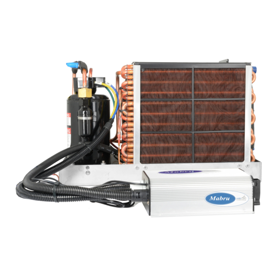
- Page 1 MARINE SELF CONTAINED AIR CONDITIONING SYSTEM INSTALLATION MANUAL...
-
Page 2: Table Of Contents
TABLE OF CONTENTS Introduction Safety Precautions Installation - Overview Installation - Ducting Installation - Seawater System Installation - Checklist Control Panel Operation WIRING DIAGRAM FOR 115/230V FOR AC WIRING DIAGRAM FOR 12V DC Troubleshooting Error Codes Warranty & Returns +1 888 818 2814 support@mabrumarine.com... -
Page 3: Introduction
INTRODUCTION Thank you very much for purchasing our SC series marine self-contained air conditioning unit! This manual provides proper installation information on the Mabru air conditioning units (a/c units). Improper installation procedures can result in unsatisfactory performance and/or premature failure of these ale units. -
Page 4: Safety Precautions
SAFETY - PRECAUTIONS Never install your air conditioner in the bilge or engine room areas. Ensure that the selected location is sealed from direct access to bilge and/or engine room vapors. Do not terminate condensate drain line within three feet of any outlet of engine or generator exhaust systems, nor in a compartment housing an engine or generator, nor in a bilge, unless the drain is connected properly to a sealed condensate or shower sump pump. - Page 5 Placement of A/C Unit - The Mabru condensate base pan is equipped with vibration isolators installed in the bottom of the pan. These isolators are designed to dampen the vibration caused by the operating ale unit from transferring into the mounted surface. Care must be taken when moving the ale unit across mounting surfaces as isolators can be damaged.
-
Page 6: Installation - Overview
INSTALLATION - OVERVIEW Mount unit with condenser/evaporator coil directly behind return air grill or with at least 3" (76mm) of air circula- tion clearance if adjacent to a bulkhead or other obstruction. Compressor should be mounted away from return air grill if possible, to minimize sound level in cabin. Mounting Brackets - The four mounting brackets provided should be placed around edge of drain pan as equally spaced as possible. - Page 7 Air Filters - Air filters are necessary to remove air borne particulates from the cabin air and to keep the evapo- rator coil clean. One, and only one, air filter must be installed for each air conditioner unit. Install the air filter either on the ale unit or in the return air (RA) grill.
-
Page 8: Installation - Ducting
INSTALLATION - DUCTING Good airflow is critical for the performance of the entire system. The ducting should be run as straight, smooth and taut as possible, minimizing the number of 90˚ bends (two 90˚ bends can reduce airflow by 25%). THE FOLLOWING IS A SUMMARY OF PROPER DUCTING CONNECTIONS. -
Page 9: Installation - Seawater System
INSTALLATION - SEAWATER SYSTEM Several guidelines should be followed during the installation of the seawater system. If the circulation pump is centrifugal and not self-priming, it must be mounted so that it is always at least one foot below the water line regardless of which tack the vessel is on. - Page 10 The following is a summary of the seawater system installation: Install the seawater scoop thru-hull inlet as close to the keel and as far below the water line as possible, facing forward. Bed the scoop with a marine sealant designed for underwater use. Install a bronze, full flow seacock on the seawater scoop thru-hull inlet.
- Page 11 SEAWATER PUMP, COOLING WATER PIPE, DEAIN PIPING INSTALLATION - SEAWATER SYSTEM Scoop type thru-hull, ball valve, strainer, and sea water pump must be installed below waterline. waterline Seawater strainer must be installed below level of the sea water pump. strainer sea water pump Be sure to use stainless steel hose cramp...
- Page 12 Sea water outlet Be sure to use stainless steel hose cramp every hose connections. waterline Drain outlet Seawater outlet located just above the waterline, typically in the boot stripe. Drain must include a trap to prevent odors from being drawn up. Check all water connections for leaks and all hose clamps for looseness.
- Page 13 FITTING Select a proper duct in accordance with A/C unit model. 1. 1. Follow the deawing procedures for duct installation.. Use a well-insulated flexible duct to prevent the dew condensation water during cooling mode.
-
Page 14: Installation - Checklist
INSTALLATION - CHECKLIST SEAWATER COOLING SYSTEM Speed scoop located as far below the water line and as close to the keel as possible Shut off valve (seacock) and speed scoop properly sealed and tight Seawater pump is at least one foot below water line and securely mounted Strainer mounted below pump with access to filter Double/reversed stainless steel hose clamps on all hose connections Teflon tape on all threaded connections... - Page 15 Electrical The wiring diagram is provided with the unit. If that diagram is damaged or if you need a copy, please call Mabru with the unit part number, serial number, and wiring diagram number, all of which are located on the unit data plate.
-
Page 16: Control Panel Operation
CONTROL PANEL OPERATION To Switch degree units between F˚ and C˚: For the new Color Touch screens: Navigate on the menu and select temperature format. Then select between the unit options. For Black and White touch screens: Keep and hold Up and Down Buttons ( ) for about 5 seconds until you hear the beep. - Page 17 Control panel Product features Fan speed Room temerature Mode Indicator Set temperature mode ON/OFF Fan speed Switch Switch Set temperature Operation mode switch adjustment switch Main display Room temperature & Set temperature AUTO mode 2.Operation room temperature MANUAL mode n i l set temperature mode button Turns...
- Page 18 Control panel operation Control panel operation 1.Stand-by mode Control panel operation 1.Stand-by mode 1.Stand-by mode room temperat room temperature room temperature mode mode room temperature mode mode room temp mode 2.Operation 2.Operation 2.Operation 2.Operation cooling heating cooling heating n i l n i l 2.Operation mode button...
- Page 19 3-1. Set Temperature room temparature set temparature The operation mode “AUTO” will be lit when auto operating while “MAN- UAL” when manual operating. room temperature FAN button TEMP button 3-2. Fan speed Push Push Push Push Push Push Press the FAN button to select the operation mode and fan speed. 4.Turning the system off Stand-by mode : only room temerature will be indicated...
-
Page 20: Wiring Diagram For 115/230V For Ac
WIRING DIAGRAM FOR 115/230V FOR AC +1 888 818 2814 support@mabrumarine.com Page No.20... -
Page 21: Wiring Diagram For 12V Dc
WIRING DIAGRAM FOR 12V DC Towards AC Unit SC_DC Retun Temp. Sensor 12V DC Energy Supply harness To Battery Battery 12V DC To pump +1 888 818 2814 support@mabrumarine.com Page No.21... -
Page 22: Troubleshooting
TROUBLESHOOTING WHEN MARINE AIR CONDITIONER DOES NOT START. Probable Cause: A/C unit circuit breaker is off. Recommended Action: Turn on the circuit breaker. Probable Cause: Power switch of control panel is off. Recommended Action: Turn on the power switch of control panel. Probable Cause: Compressor protection is activated. - Page 23 TROUBLESHOOTING Probable Cause: Seawater flow is obstructed. Recommended Action: Check the seawater strainer and scoop type thru-hull and clean them if necessary. Check if seawater is discharged smoothly. Probable Cause: Air entrainment to seawater pump. Recommended Action: Purge the air completely from the pump. Probable Cause: Seawater temperature is too high for cooling or too low for heating.
-
Page 24: Error Codes
power button ERROR CODES CODE DEFINITION OF ERROR ISSUE POSSIBLE CAUSES POSSIBLE CORRECTION ERROR "Check for operation panel and Room temperature Compressor RJ45 cable Failure of room temperature sensor sensor error stops Replace them as necessary" "Check for the radiator Radiator temperature sensor and temperature... - Page 25 Turns solid ERROR CODES power button CODE DEFINITION OF ERROR ISSUE POSSIBLE CAUSES POSSIBLE CORRECTION ERROR 1 Current overload protection (2 short 2 long) 2 Undervoltage protection (3 short 2 long) 3 Voltage Overload protection (4 short 2 long) 4 Startup failure (5 short 2 long) LED Flashing Restart unit / restart the 5 Compressor low speed protection...
- Page 26 ERROR CODES CODE DEFINITION OF ERROR ISSUE POSSIBLE CAUSES POSSIBLE CORRECTION ERROR "Seawater temperature too high/low (below 0* at heating mode, below 15* "Check for seawater outlet Compressor at cooling mode) Seawater temperature stops error Check if selected ""MODE"" Pump stops Operation mode is wrong - cooling is correct"...
-
Page 27: Warranty & Returns
OWNER’S LIMITED WARRANTY POLICY This Warranty is made to a purchaser (“owner” or “you”), who acquires the Mabru Power Systems, Inc. (“Mabru”) -manufactured product or component (the “Mabru product”) for his or her own use. 1. WHAT’S COVERED What does the Limited Warranty cover? The Mabru products under this limited warranty are to be free from defects in material and workmanship at the time of sale and under normal use. - Page 28 SOME STATES DO NOT ALLOW THE EXCLUSION OR LIMITATION OF INCIDENTAL OR CONSEQUENTIAL DAMAG- ES, SO THE ABOVE LIMITATIONS MAY NOT APPLY TO YOU. ANY IMPLIED WARRANTY, INCLUDING THE IMPLIED WARRANTY OF MERCHANTABILITY AND FITNESS FOR ANY PURPOSE, IS LIMITED TO THE DURATION OF THIS LIMITED WARRANTY.
- Page 29 If the customer already knows of an authorized Servicing Dealer, the Servicing Dealer should be contacted direct- ly. 2) Second option: If the customer contacts the Mabru Customer Service Department for an authorized Servic- ing Dealer and there are none in the particular area, Mabru may authorize the use of a local Servicing Dealer, in which event Mabru will work with the local Servicing Dealer to assist in any way possible.
- Page 30 Direct Expansion SC Series Self Contained units OEM or Dealer Installed W/ included control 2 Year Warranty 1st Year parts and labor, 2nd Year parts only. Not to exceed three (3) years from date of production. MABRU – Air Handlers Chilled Water Systems OEM or Dealer Installed 2 Year Warranty 1st Year parts and labor, 2nd Year parts only.
Need help?
Do you have a question about the SC Series and is the answer not in the manual?
Questions and answers