Table of Contents
Advertisement
Quick Links
Advertisement
Table of Contents

Related Manuals for Unipulse F377A


Summary of Contents for Unipulse F377A
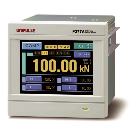
- Page 1 F377A DIGITAL INDICATOR OPERATION MANUAL 18JUL2012REV.3.06...
- Page 2 Thank you very much for purchasing our Digital Indicator F377A. For good performance, and proper and safe use of the F377A, be sure to read this operation manual and properly understand the contents of it before use. Also, carefully keep this operation manual so that it can be referred to at any time.
- Page 3 Safety Precautions ● Indications for safe use and their meanings In this manual, precautions for using the F377A Digital Indicator safely are indicated as follows. Be sure to follow the precautions given here because they are important descriptions relating to safety.
- Page 4 RoHS-Compliant Product ● About the signal I/O terminal block CAUTION Misuse may cause the risk of injury to persons or damage to property. For connection to the signal I/O terminal block, wire correctly after checking the signal names and terminal block numbers. Also, turn off the power of the main body before connection / wiring to the signal I/O terminal block.
- Page 5 What is RoHS? M E M O...
-
Page 6: Table Of Contents
■ F377A screen configuration ........ - Page 7 CONTENTS ■ Registration method at decimal place ....... . 34 4-8.
- Page 8 7-3. F377A Block Diagram ........
- Page 9 CONTENTS 8 SUPPLEMENTS ..........85 8-1.
- Page 10 CONTENTS CONTENTS <Expansion> 1 EXP. HOLD FUNCTIONS........97 1-1.
- Page 11 CONTENTS 4-1. CR Characteristic (Primary) Digital Filter ....... . . 127 ■...
- Page 12 STANDARD...
- Page 13 M E M O...
-
Page 14: Outline
Be sure to check them before use. F377 DYNAMIC FORCE PRO CESSOR 05JAN2005REV.1.00 F377A body ・ ・ ・ 1 F377A operation manual ・ ・ ・ 1 External input / output connector ・ ・ ・ 1set Jumper wire ・ ・ ・ 1 [ ] (for connectingcurrent output device) -
Page 15: Appearance Description
This is the touch panel display for displaying an indicated value and graph set value and for setting various setting items of the F377A. During measurement, a comparison display, hold display and graph display can be selected according to the function in use. -
Page 16: Rear Panel
1 OUTLINE ■Rear panel Chapter RS-232C connector DC power input terminal block Signal input / output connector Frame ground Analog input / output Protective ground connector Option board mounting slot Analog input / output connector - MONITOR + MONITOR SHIELD A.GND in -... - Page 17 → page32 "Calibration value selection by external signal input" See the section on "External I/O connection" page 21 for connection. SI/F The 2-wire serial interface for coupling a UNIPULSE printer, external display, etc. See the section on "SI/F connection" page 21 for connection.
- Page 18 1 OUTLINE DC power input terminal block Connect the DC power cord. The power supply voltage is 24V DC (±15%). Chapter Adaptable crimp terminal [TMEV1.25-3S] Frame ground (functional ground) F.G. terminal. (There is continuity between the casing and F.G. terminal.) Protective ground Protective ground terminal.
-
Page 19: Installation & Connection
2 INSTALLATION & CONNECTION INSTALLATION & CONNECTION 2-1. Installation Chapter To install the F377A into a control panel, use the following procedure. Make a hole in the panel according 92mm – to the panel-cut dimensions. Panel-cut dimensions 92mm Panel thickness 0 –... -
Page 20: Analog Input / Output Terminals Connection
Loosen the screws (two) with a screwdriver. Loosen. (Turn Remove the terminal block by giving it a counterclockwise..) strong pull. Loosen. (Turn counterclockwise..) Attention Insert side When installing the terminal block to the F377A body, check its orientation. (See the illustration at the right.) Right side... -
Page 21: Voltage・Current Connection
(Set「Analog Input Sel.」in calibration when you use it by current input.) *3,4 F377A and the device connected should be grounded when you use them. (Usually, one side of shield wire should be connected to avoid the cause of faulty operation by forming ground loop. -
Page 22: F Connection
2 INSTALLATION & CONNECTION ■SI/F connection The 2-wire serial interface has connective ability for coupling a UNIPULSE printer, external display, etc. Connect from A11 and A12 of the external input/output connector. The interface is nonpolarized and up to three external instruments may be connected. - Page 23 COM2 terminal. Short-circuiting is effected by means of a contact (such as a relay or a switch) or a noncontact (such as a transistor or an open-collector TTL). Chapter Open → OFF F377A Inside +12V Short → ON Push...
-
Page 24: Rs-232C Interface Connection
Cabling diagram assignments) of the equipment you use. CA81-232X(optional) ■Voltage output connection The monitor output terminal is an interface to extract analog voltage proportional to sensor signal inputs. ← F377A inside outside → + MONITOR + External equipment - MONITOR -... -
Page 25: Connecting To Cage Clamp Terminal Block
2 INSTALLATION & CONNECTION ■Connecting to cage clamp terminal block The output terminal D/A option is using the cage clamp system terminal stand. Please connect in the following procedure. Strip the casing 5 - 6mm on the cable to be 5 to 6mm Chapter connected. -
Page 26: Setting Procedure
3 SETTING PROCEDURE SETTING PROCEDURE 3-1. Screens And Operations ■Setting modes tree Ordinary display screen Chapter Setting menu screen Work Setting System Setting Operation RS-232C Setting Comp. Setting Hold Setting Graph Setting PAGE1 PAGE1 PAGE1 PAGE1 PAGE1 Digital Filter (P38) Com. Mode (P67) HH Limit (P42) - Page 27 3 SETTING PROCEDURE Chapter Exp. Setting Protect / Init Self Check Calibration PAGE1 PAGE1 PAGE1 LCD Check (P87) Analog Input Sel. (P32) Work Protect (P86) See the Expansion of KEY Check (P87) Zero Cal. (P33) System Protect (P86) this manual. Option Setting Cal.
-
Page 28: F377A Screen Configuration
3 SETTING PROCEDURE ■F377A screen configuration [Ordinary display screen] Setting Chapter Set value entry from the ordinary display screen Measurement [Setting menu screen] Mode buttons Back [Set value selection screen] HOME Setting buttons [Set value entry screen] Back Measurement Back... -
Page 29: About A Setting Call
3 SETTING PROCEDURE ■About a setting call In this manual, a setting function call is described as follows. Example) Digital filter SET. System setting Operation Page 1 → → → ↑ ↑ ↑ Setting menu Item classification Page Chapter This call can be made by the following procedure. Press the [SET.] button on the ordinary display screen. -
Page 30: Calibration
4 CALIBRATION CALIBRATION About calibration Calibration is performed for matching the F377A to voltage・current output device (sensor). The following two types of calibration are available for the F377A. ● Equivalent input calibration Calibration is performed without an actual load by entering the output value (V or mA) of the voltage・current output device (sensor) and the indicated value of the time by the keys. -
Page 31: Calibration Procedures
4 CALIBRATION 4-1. Calibration Procedures Follow the steps below to perform equivalent input calibration and actual load calibration. Release the calibration protection. 4-2. Calibration Protect Set the calibration value No. 4-3. (Set "0" for use with only one selection.)(This step Calibration Selecttion may be omitted if there is no change.) Set the analog input (Voltage・current) excitation 4-4. -
Page 32: Calibration Protect
4 CALIBRATION 4-2. Calibration Protect Calibration-related set values can be protected so that they will not be changed by misoperation. When Cal. Protect is ON, no change can be made while the alarm sounds. :Protected OFF :Unprotected How to set SET. Protect / Init. -
Page 33: Calibration Value Selection By External Signal Input
4 CALIBRATION ■Calibration value selection by external signal input With this function, four types of calibration values can be selected with external selector signals CAL0 and CAL1 (when the calibration value selection setting is external). Set EXT 0 by pressing button on the CALIBRATION screen. According to the input conditions of external signal inputs CAL0 and CAL1, the display changes as EXT 0 to EXT 3. -
Page 34: Zero Calibration
4 CALIBRATION First select the category, and then select the unit and determine with the [OK] button. Select by scrolling with the * Even if the unit is changed, the display button. value (calibration value) will not change. 4-6. Zero Calibration Set the zero point in no-load condition. -
Page 35: Equivalent Input Calibration
4 CALIBRATION 4-7. Equivalent Input Calibration Set the output value and reading of the voltage・current output device (sensor). Output value: -10.00 - 10.00V or -20.00 - 20.00mA (0 is excluded.) Display value: -99999 - 99999 (0 is excluded.) How to set Press the [SET.] button. -
Page 36: Actual Load Calibration
4 CALIBRATION 4-8. Actual Load Calibration Set the actual load value under an actual load. Setting range: -99999 - 99999 (0 is excluded.) How to set SET. Calibration Page 1 → → Press the [SET.] button. (refer to page 33) Press the [Calibration] button. (refer to page 33) Press the [Actual Cal.] button. -
Page 37: 4-10.Digital Offset(This Step May Be Omitted If There Is No Change.)
4 CALIBRATION 4-10. Digital Offset (This step may be omitted if there is no change.) By using the digital offset function, the value obtained by subtracting the set value from the indicated value is displayed. This function is convenient when zero cannot be obtained with no load for some reason or for offsetting. -
Page 38: Setting Of Functions
5 SETTING OF FUNCTIONS SETTING OF FUNCTIONS 5-1. Digital Zero The indicated values is forcedly zeroed. Digital zero by means of Keys 1) Press the [DZ] button.in the ordinary display screen (COMP・HOLD・GRAPH) 2) Press the [YES] button to perform the digital zero. Press the [NO] button to go back to Chapter the previous screen without... -
Page 39: Digital Filter
5 SETTING OF FUNCTIONS 5-2. Digital Filter The digital filter is a function for reducing drifts of the indicated value by means of a moving average of data converted from analog to digital. With an increase in the number of filterings, the indicated value becomes more stable, but the response to inputs becomes slower. -
Page 40: Zero Tracking (Zt)
5 SETTING OF FUNCTIONS 5-5. Zero Tracking (ZT) Gradual changes in the zero point due to drifts etc., are automatically tracked for correction. ・When displacement of the zero point is within the set count of tracking and it continues more than the set time, it is automatically made zero by Zero Tracking function. -
Page 41: Display Language Selection
Chapter By this function, the indicated value is automatically printed to the UNIPULSE printer coupled with the F377A through the SI/F when the indicated value is stable. (Set the stable parameters by the Motion Detect.) When Near Zero is OFF, Indicated value is held until Near Zero turns ON after stable turned ON. -
Page 42: Indicate Color
At hold-off time, the held value is automatically printed to the UNIPULSE printer coupled with the F377A through the SI/F. At hold-off time, hold values and real time values are output in the GROSS area and NET area, respectively. Others are the same as in the setting of "OFF". -
Page 43: Hi Limit / Lo Limit / Hh Limit / Ll Limit
5 SETTING OF FUNCTIONS ■HI limit / LO limit / HH limit / LL limit How to set SET. Work Setting Comp. Setting Page 1 → → → Simple setting call Press any of the [HH], [HI], [LO] and [LL] buttons at the bottom of the indicated value display screen to go direct to the entry screen. -
Page 44: Near Zero
5 SETTING OF FUNCTIONS - Hysteresis operation Indicated Value HI Limit Hysteresis Range LO Limit + Time - HI Output HI Status Display Output OFF Output ON Output OFF Status OFF Status ON Status OFF LO Output LO Status Display Output ON Output OFF Output ON Status ON... -
Page 45: Comparison Output Selection
5 SETTING OF FUNCTIONS ■Comparison output selection The number of HI-LO limits can be changed. Correspondence between comparison screens and external I/O output terminals. Mode HI limit operation LO limit operation H4 / L0 HI-1 to HI-4 None H4 / L0 HI-4 HI-3 HI-2... -
Page 46: Alarm Hi And Lo Limits
The operation of each hold will be described in detail. ■Hold setting --- Common --- Hold mode The F377A includes 10 hold modes as shown in the table below. In the peak, valley, peak-to-peak and average modes, section setting is required. Select all section, external signal, external signal+time, level+time, level. - Page 47 5 SETTING OF FUNCTIONS Simple setting call Press the [MODE] button at the bottom of the indicated value display screen to go direct to the hold mode entry screen. Section time If you set the hold section setting in the hold function setting to external signal+time or level+time, set the time.
-
Page 48: Hold Setting
5 SETTING OF FUNCTIONS Level condition (hold section setting; Level + Time or Level, or detection start condition; External + Level) Setting range: Passed, Passed HI, Passed LO - Passed: Detection starts when the indicated value passes the Hold start level. - Passed HI: Detection starts when the indicated value passes the Hold start level in the direction from smaller toward larger values. -
Page 49: Hold Setting
5 SETTING OF FUNCTIONS Relative minimum count Setting range: 0001 - 99999 How to set SET. Work Setting Hold Setting Page 1 → → → Relative magnification Setting range: ×0.25, ×0.50, ×0.75, ×1.00, ×1.25, ×1.50, ×2.00, ×3.00, ×4.00 How to set SET. - Page 50 5 SETTING OF FUNCTIONS Inflection front (rear) slope time setting is the number of samplings. Since the F377A's sampling speed is 2000 times/sec., one sampling is 0.5msec. Therefore, setting of the interval at 100 means setting of 50msec. Caution regarding inflection point hold...
-
Page 51: Hold Setting
5 SETTING OF FUNCTIONS ■Hold setting --- Average value --- Average sample number In average hold, the average in each sampling can be detected for up to 5 seconds. Then, if the average sample number is set at 2 or more, the representative value of the sampling values by the set number (average by the number) is adopted as the sampling data used for average calculation. - Page 52 5 SETTING OF FUNCTIONS Peak hold The maximum value (peak) in the positive direction of the specified section is held. The section is specified by the setting of “all section”, “external signal”, “external signal+time”, “level+time”, or “level”. (Example) All section peak hold t1: A delay time between the instant +...
- Page 53 5 SETTING OF FUNCTIONS Peak-to-Peak (P-P) hold The difference value between the peak and valley over the specified section is held. The section is specified by the setting of “all section”, “external signal”, “external signal+time”, or “level+time”. (Example) All section Peak-to-Peak (P-P) hold t1: A delay time between the instant +...
- Page 54 5 SETTING OF FUNCTIONS Inflection point hold Detection starts when the SECTION signal is inputted and also the Level Condition is met in comparison of the Hold Start Level and indicated value. Detection is performed as long as the SECTION signal is ON.The hold is released by turning on the T/H signal as a reset signal. The H/E output signal is on between the instant when the hold starts and the instant when the T/H signal is turned on.The next detection is started when the SECTION signal is turned on again even if the T/H signal is not turned on.
-
Page 55: How To Specify The Hold Detection Section(Peak, Valley, P-P, Average)
5 SETTING OF FUNCTIONS ■How to specify the hold detection section(Peak, Valley, P-P, Average) All section By this method, the hold detection section is externally specified by the T/H signal. Detection starts with the T/H signal ON to perform each hold operation. According to the ON/OFF state of the T/H signal, detection and tracking are repeated. - Page 56 5 SETTING OF FUNCTIONS External signal + time Hold is detected during the predetermined time (hold section time) from the point in time when the SECTION signal is turned on. The hold is released by turning on the T/H signal as a reset signal.The next detection is started when the SECTION signal is turned on again even if the T/H signal is not turned on.
-
Page 57: 5-12.Multi-Hold Function
5 SETTING OF FUNCTIONS Level (only Peak and Valley) By this method, the hold detection section is from the point in time when the indicated value crosses the Hold Start Level until it crosses the Hold Stop Level. The hold is released by turning on the T/H signal as a reset signal. -
Page 58: About Changing Of The Setting Work
5 SETTING OF FUNCTIONS I/O terminal block CAUTION B1 or B7 COM2 It takes 15msec at the maximum for the changed work No. WORK0 to become effective. During this section, which work is measured is undefined. WORK1 Also, when the work is switched, the hold and graph WORK2 functions are reset under the after-switching work conditions irrespective of the previous operation. -
Page 59: 5-13.Measurement Work Selection
5 SETTING OF FUNCTIONS 5-13. Measurement Work Selection Select the method for specifying the measurement work. COM.: Measurement work specification by external input becomes ineffective, and only measurement work specification by communication (RS-232C, CC-Link (option) or DeviceNet (option)) becomes effective. EXT.: Measurement work specification by communication (RS-232C, CC-Link (option) or DeviceNet (option)) becomes ineffective, and only measurement work specification by external input becomes effective. -
Page 60: 5-16.B8 Off Detection Wait
5 SETTING OF FUNCTIONS 5-16. B8 OFF Detection Wait This is convenient in hold controlled by the SECTION signal. Operationally, detection/hold section is assured as in the case of B6 OFF Detection Wait. The timer functions so as to also ignore chattering when the OFF edge is detected. Setting range: 0.00 - 1.00 sec. -
Page 61: Graph Plotting
5 SETTING OF FUNCTIONS CAUTION If the hold point is simply renewed without renewing the graph, the value will differ from the hold point on the graph. In such a case, the hold point alarm status is displayed. Detection section display By plotting a graph at the same time as the hold function, a cobalt line indicating the detection section is displayed at the bottom of the X-axis. - Page 62 5 SETTING OF FUNCTIONS External Graph plotting starts with the GRAPH Start/Stop key input or the GRAPH TRIG external input ON. Plotting ends on one screen at the predetermined time of the X end point. + START/STOP (Key) GRAPH TRIG (external input) 1.0msec more Plotting Section X(TM) end point...
-
Page 63: Graph Mode
5 SETTING OF FUNCTIONS ■Graph mode Set the graph plotting mode. Setting range: Continued, Ext, Level, Ext+Level How to set SET. Work Setting Graph Setting Page 1 → → → ■Interval time If you select "Continued" in the graph function setting, set the graph plotting operation interrupting time from clearing the screen until moving to the next graph plotting operation. -
Page 64: Time) End Point
5 SETTING OF FUNCTIONS ■X(Time) end point Set the time to display by one screen. Setting range: 00.1 - 99.9 sec. How to set SET. Work Setting Graph Setting Page 1 → → → Simple setting call Press the [X] button on the graph display to go direct to the X end point entry screen. ■Y(Load) start point and Y(Load) end point Chapter Setting range: -99999 - 99999 (where Y start point <... -
Page 65: 5-18.Voltage Output
The output level is approx. 0.6V per 1V at voltage input and approx. 0.3V per 1mA at current input. - Example of output equivalent circuit and external equipment connection F377A inside Vin + , Vin - +... -
Page 66: 5-20.Event Output At The End Of Graph Plotting
5 SETTING OF FUNCTIONS CAUTION By the selection of each LOCK function, measurement work that can be specified externally is limited to WORK00 to WORK07. How to set SET. System Setting Operation Page 2 → → → 5-20. Event Output at the End of Graph Plotting Each time a graph is plotted on screen, a pulse signal is output (the pulse width is 200msec). -
Page 67: 5-22.Rs-232C Interface
5-22. RS-232C Interface The RS-232C is an interface to read the indicated value and status of the F377A and to write parameters into the F377A. This interface is convenient to process controls, totals, records, etc., by connecting the F377A to a computer, process controller, sequencer or the like. -
Page 68: Rs-232C Interface Setting
5 SETTING OF FUNCTIONS ■RS-232C interface setting Set the RS-232C communication conditions of the F377A. Communication mode Normal, Continue, Print How to set SET. System Setting → RS-232C Setting Page 1 → → Baudrate 9600, 19200, 38400, 57600bps How to set SET. -
Page 69: Communication Format
1.Normal - Reading the indicated value (sign, 5-digit indicated value, decimal point) Host A CR + F377A Delimiter * If the indicated value has no decimal point, a decimal point follows the numerical value. - Reading the status (7-digit) Host... - Page 70 5 SETTING OF FUNCTIONS - Writing parameters Work Setting HH Limit ± Protect Work Setting HI Limit ± Protect Work Setting ± LO Limit Protect Work Setting ± LL Limit Protect Work Setting Hysteresis Protect Cal. Select ⑥ (Calibration Protect) Digital Offset ±...
- Page 71 Passed LO Cal.2 Ext+Level Beyond Cal.3 Below EXT. Chapter - Reading waveform data Host ± F377A …… 00 - 19 Data Section No. 00 - 19 Decimal Point and Five digits Data1 Data Section No. ± ± …… Delimiter Decimal Point and Five digits Data9...
- Page 72 - Reading parameters Host W W F377A Delimiter Set Value No. Set Value No. The same format as write-in of set values. - Commands (Host→F377A) Digital Zero C G Digital Zero reset C H Print instruction C I (This will issue print a command onto SIF.) 2.Continue...
-
Page 73: Bcd Data Output (Option)
6-1. BCD Data Output (Option) The BCD data output is an interface to extract the indicated value of the F377A as BCD data. This interface is convenient to process controls, totals, records, etc., by connecting the F377A to a computer, process controller, sequencer or the like. -
Page 74: Bcd Output Select
6 OPTION ■BCD output select When "External" is set by the BCD Output Select setting, the output data is switched by A15. In the case of external selection, read after at least 2 cycles. When COM and A15 are open: real time value, When they are short-circuited:hold value Output data: Realtime, Hold, EXT. -
Page 75: Equivalent Circuit
6 OPTION ■Equivalent circuit -Output The signal output circuit is operated through a TTL open collector. F377A Vext Inside Outside Vceo=30V(max) Ic =30mA (max) Internal transistor status Output pin level Output data Negative Positive Output data Negative Positive H L L... -
Page 76: Self Check
D/A Converter (Option) A D/A converter is provided for obtaining analog output synchronized with the indicated value of the F377A. The analog output ranges are -10 - +10V output and 4 - 20mA constant-current output. By using the D/A zero setting and D/A full scale setting functions, analog output can be obtained between zero (0V, 4mA) and full scale (10V, 20mA) with respect to the predetermined digital value. -
Page 77: Scale Setting Value Selection
6 OPTION - Taking voltage output signals F377A Connect external equipment (2kΩ or more ← Inside Outside → load resistance) to + and - of the F377A. + + External equipment - Load resistance: - 2kΩ or more - Taking current output signals F377A Connect external equipment (350 Ω... -
Page 78: D/A Output Select
6 OPTION ■D/A output select Hold, Realtime, Zero scale, Full scale Hold : Output is produced in synchronization with the indicated value. Realtime : Output is produced in synchronization with the sensor input value. Zero scale : Output is fixed at zero output (0V or 4mA). Full scale : Output is fixed at full scale (10V or 20mA). -
Page 79: External I/O (Source Type (Isc) Option)
External I/O (Source type (ISC) option) The source type external input/output signal is an option which can be changed external input/ output signal of F377A to source type. (The standard is sink type.) The connection of external input/output signal is the minus common. -
Page 80: Specifications
7 SPECIFICATIONS SPECIFICATIONS 7-1. Specifications ■Analog section Signal input range -10 ~10V or -20~20mA Voltage input: Input impedance 1MΩ or more Current input: Input resistance Approx.250Ω -12~12V or -24~24mA Absolute maximum input Performed by digital computation Zero and gain adjustment Accuracy Non-linearity: Within 0.02%FS±1 digit (at a 10V or 20mA input) Zero drift:... -
Page 81: Standard Interfaces
7 SPECIFICATIONS ■Standard interfaces RS-232C communication interface Start/stop system Baud rate: 9600bps~57600bps SI/F (2-wire serial interface) Start/stop system Baud rate: 600bps ■Options interfaces BCD data output Open collector Output rate Can be selected from 10, 20, 50, 100, 200, 500, 1000 and 2000 times/sec. Capacity 30V, 30mA D/A converter... -
Page 82: Accessories
7 SPECIFICATIONS Dimensions 96.0W×96.0H×138.0D [mm] (excluding projected parts) + 1 Panel cutout size 92×92 mm(Board thickness:1.6~3.2㎜) - 0 Weight Approx. 1.0kg ■Accessories Operation manual ........................1 Control signal Input/Output connector..................1 Jumper wire ..........................1 Connector for BCD output (with BCD option) ................ 1 Mini screwdriver (with DAV/DAI option) ................ -
Page 83: Equipped With Bcd Parallel Data Output Interface Option
7 SPECIFICATIONS ■Equipped with BCD parallel data output interface option [Unit : mm] ■Equipped with CC-Link interface option Chapter [Unit : mm] ... -
Page 84: Equipped With Device Net Interface Option
7 SPECIFICATIONS ■Equipped with Device Net interface option [Unit : mm] Chapter... -
Page 85: F377A Block Diagram
7 SPECIFICATIONS 7-3. F377A Block Diagram Gain +MONITOR Buffer adjustment - MONITOR Low-pass Vin + 1/5 Fillter in - 250Ω Conversion Iin + A.GND Reference Standard Voltage SHIELD RS-232C FRAME Watch Serial 32bit Port External Flash Flash 256Kbyte External Lithium Serial... -
Page 86: Supplements
Although the F377A will not break down immediately even if the above messages are displayed, Sensor +error or Sensor -error indicates that an excessive voltage may be applied to the input circuit of the F377A. -
Page 87: Protect / Initialization
8 SUPPLEMENTS 8-2. Protect / Initialization ■Work setting protect Set whether to protect the set values in Work Setting from changing. Setting range: ON / OFF How to set SET. Protect / Init. Page 1 → → ■System setting protect Set whether to protect the set values in System Setting from changing. Setting range: ON / OFF How to set SET. -
Page 88: Self-Check
8 SUPPLEMENTS 8-3. Self-Check ■Self-check The self-check function includes a memory check to check the memory automatically for detecting problems, a visual check to check the display visually, a touch panel key input check and an external I/O check. ①LCD check Check the display to see that it is free from color and display defects, etc. -
Page 89: Password
8 SUPPLEMENTS ⑥COM check The data displayed under "Transmit data" is sent by pressing the button. Under "Receive data", externally transmitted data is displayed. How to set SET. Self Check COM Check → → Please transmit something information sentence from connected equipment side to the check on the reception. -
Page 90: Setting Item List
8 SUPPLEMENTS 8-5. Setting Item List ■Work setting Comparison setting (WORK0 to WORK15) Protect ○:Work Setting Protect, ◎:System Setting Protect, ●:Calibration Protect, レ:Expansion Protect Memory S:SRAM, N:NOVRAM Page Item Initial value Setting range Memory Protect HH Limit 8000 - 99999 to 99999 ○... -
Page 91: Work Setting Graph Setting (Work0 To Work15)
8 SUPPLEMENTS -Relative Maximum / Relative Minimum / Relative Difference hold- Relative Minimum Count 1 to 99999 ○ Relative magnification × 1.00 ○ Detection Start Condition 0: Ext+Level 0: Ext+Level 1: Ext Only ○ 0:x0.25 Hold Hold Section 1:x0.50 0:OFF 0:All 1:Sample 1:EXT... -
Page 92: Calibration (Cal0 To Cal3)
8 SUPPLEMENTS ■Calibration (CAL0 to CAL3) Protect ○:Work Setting Protect, ◎:System Setting Protect, ●:Calibration Protect, レ:Expansion Protect Memory S:SRAM, N:NOVRAM Page Item Initial value Setting range Memory Protect Analog Input Selection 0: ± 10V 0: ± 10V 1: ± 20mA ● Zero Calibration -... -
Page 93: Protect / Initialization
8 SUPPLEMENTS Option setting BCD output Output Select 1: Hold 0: Realtime 1: Hold 2: EXT. ◎ Output Rate 3: 100 /s 0: 10 1: 20 2: 50 3: 100 4: 200 5: 500 6: 1000 7: 2000 [ /s] ◎ Option setting D/A output Output Select 1: Hold 0: Real Time 1: Hold 2: Zero Scale 4: Full Scale ◎... -
Page 94: Expansion
EXPANSION... - Page 95 M E M O...
- Page 96 Expansion Function Expansion Function The F377A is designed so as to be able to perform more operations by selecting the following functions from the Expansion menu. Expansion Comparison Setting ● Before Value Comparison (P116) ● Relative Value Comparison (P120) Expansion Hold Setting ● Double Hold (P98)
- Page 97 Expansion Function M E M O...
-
Page 98: Exp. Hold Functions
1 EXP. HOLD FUNCTIONS EXP. HOLD FUNCTIONS Chapter 1-1. Double Hold Specifically combined two types of hold functions are performed simultaneously in one Hold Section. You can select hold modes from 26 modes in the following table. Hold A Hold B SECTION None None... -
Page 99: Double Hold Setting
1 EXP. HOLD FUNCTIONS Also, the Comparison Setting menu is dedicated. Chapter ■Double hold setting ON / OFF Initial value: OFF How to set SET. Exp. Setting Exp. Hold Set. Page 1 → → → When this setting is ON, you can set Hold A and Hold B in Hold Setting. ■Hold operations For the operations of the HOLD buttons and HI/LO Limit judgment outputs, see the F372 Operation Manual (Standard). - Page 100 1 EXP. HOLD FUNCTIONS A: Peak hold B: None The maximum value in the section specified is held. Chapter When the Section setting is External Sensor Input Value Hold Value B Hold Value A SECTION HOLD A Status Display PEAK A Blink Status Display HOLD B Status Display...
- Page 101 1 EXP. HOLD FUNCTIONS A: P-P hold B: None The difference between the maximum value and minimum value in the section specified is Chapter held. When the Section setting is External Sensor Input Value Hold Value B Hold Value A SECTION HOLD A Status Display P-P A Blink...
- Page 102 1 EXP. HOLD FUNCTIONS A: Inflection point hold B: None When the Hold Start Level is detected after turning-ON of the SECTION signal, Inflection Chapter Point hold detection starts. For the Hold Start Level, Detection Start Condition can be selected.Also, the value is maintained until the T/H signal turns ON with the hold Detection Start Condition External Only.
- Page 103 1 EXP. HOLD FUNCTIONS A: Sample hold B: Peak hold An arbitrary point is held when the SECTION signal is ON. Chapter The maximum value in the section specified is held. The value is maintained until the T/H signal turns ON. Sensor Input Value Hold Value B Hold Value A SECTION...
- Page 104 1 EXP. HOLD FUNCTIONS A: Sample hold B: P-P hold An arbitrary point is held when the SECTION signal is ON. Chapter The difference between the maximum value and minimum value in the section specified is held. The value is maintained until the T/H signal turns ON. Sensor Input Value Hold Value A Hold Value B...
- Page 105 1 EXP. HOLD FUNCTIONS A: Sample hold B: Inflection point hold When the Hold Start Level is detected An arbitrary point is held when the SECTION signal is ON. Chapter after turning-ON of the SECTION signal, Inflection Point hold detection starts. For the Hold Start Level, Detection Start Condition can be selected. Also, operation can be performed without using the Hold Start Level with the hold Detection Start Condition External Only.
- Page 106 1 EXP. HOLD FUNCTIONS A: Peak hold B: Valley hold The maximum value and minimum value in the section specified by the SECTION signal Chapter are held. The value is maintained until the T/H signal turns ON. When the Section setting is External Hold Value A Sensor Input Value Hold Value B...
- Page 107 1 EXP. HOLD FUNCTIONS A: Valley hold B: P-P hold The minimum value and the difference between the maximum value and minimum value in Chapter the section specified by the SECTION signal are held. The value is maintained until the T/H signal turns ON. When the Section setting is External Sensor Input Value Hold Value B...
- Page 108 1 EXP. HOLD FUNCTIONS A: Average hold B: Valley hold The average of and the minimum value in the section specified by the SECTION signal are Chapter held. The value is maintained until the T/H signal turns ON. Sensor Input Value Hold Value A Hold Value B SECTION HOLD A...
- Page 109 1 EXP. HOLD FUNCTIONS A: Relative maximum hold B: Relative minimum hold When the Hold Start Level is detected after turning-ON of the SECTION signal, Relative Maximum / Chapter Minimum hold detection starts. For the Hold Start Level, Detection Start Condition can be selected. Also, the value is maintained until the T/H signal turns ON with the hold Detection Start Condition External Only.
-
Page 110: Hi/Lo Limit Comparisons Of Double Hold
1 EXP. HOLD FUNCTIONS A: Relative minimum hold B: Relative difference hold When the Hold Start Level is detected after turning-ON of the SECTION signal, Relative Minimum and Chapter Relative Difference (difference between the Relative Maximum and Relative Minimum) hold detection starts. For the Hold Start Level, Detection Start Condition can be selected. Also, the value is maintained until the T/H signal turns ON with the hold Detection Start Condition External Only. -
Page 111: Sample Hold Trigger Edge Selection
1 EXP. HOLD FUNCTIONS * OK is displayed each on the LCD screen as hold value A is OK, and hold value B is OK. Chapter - External I/O pin assignments for Double Hold COM1 COM2 - - HI-B WORK0 HI-A WORK1 WORK2 LO-A... -
Page 112: Sample Trigger Selection Setting
1 EXP. HOLD FUNCTIONS Chapter ● In the case of ON-edge operation ● In the case of OFF-edge operation where the hold modes are where the hold modes are A: Sample hold A: Sample hold B: Inflection Point B: Inflection Point When the Detection Start Condition is External Only When the Detection Start Condition is External Only Sensor Input Value... -
Page 113: Auto Reset Selection At The Start Of Hold Detection
1 EXP. HOLD FUNCTIONS 1-3. Auto Reset Selection at the Start of Hold Detection Chapter As standard, hold reset is automatically performed at the start of each Hold Section. This allows simple control as control can be performed by the SECTION signal alone without inputting the T/H signal. When Hold Auto Reset is ON in Externally specified section Hold Peak hold SECTION Upon turning-ON of the SECTION... -
Page 114: Hold Auto Reset
1 EXP. HOLD FUNCTIONS ■Hold auto reset Chapter ON / OFF Initial value: ON How to set SET. Work Setting Hold Setting Page 1 → → → ・OFF: After a hold is confirmed, the next detection is not started until the T/H signal is turned on even if the SECTION signal is turned on. -
Page 115: Renewal Of Hold Value
1 EXP. HOLD FUNCTIONS 1-5. Renewal of Hold Value Chapter You can change the operation of renewing the hold value display. All Time / Hold Stop Initial value: All Time How to set SET. Exp. Setting Exp. Hold Set. Page 1 →... -
Page 116: Hold End Timing
1 EXP. HOLD FUNCTIONS 1-6. Hold End Timing Chapter The HOLD END (H/E) signal timing when Inflection Point, Relative Maximum, Relative Minimum or Relative Difference hold is used can be changed. Hold Sct / Detect Sct Initial value: Detect Sct How to set SET. -
Page 117: Exp. Comparison Functions
2 EXP. COMPARISON FUNCTIONS EXP. COMPARISON FUNCTIONS 2-1. Before Value Comparison Chapter ■Before value comparison ON / OFF Initial value: OFF How to set SET. Exp. Setting Exp. Comp. Set. Page 1 → → → In addition to the HI/LO Limit comparisons of hold values, the difference between the presently- measured hold value and the previously-measured hold value can be judged. -
Page 118: Screens Appearing When Before Value Comparison Is Selected
2 EXP. COMPARISON FUNCTIONS ■Screens appearing when before value comparison is selected Before-value-comparison-specific measurement screens appear. Chapter Also, the Comparison Setting menu is dedicated. ■Before value renewal condition The previous hold value used for Before Value Comparison is renewed under the following conditions: 1) When the hold is canceled (except when the Before Value Regulation is exceeded) 2) When the Before Value in the Comparison Setting menu is changed by inputting a value in a similar manner to set values. -
Page 119: Before Value Regulation
2 EXP. COMPARISON FUNCTIONS COM1 COM2 - - DF-HI WORK0 WORK1 WORK2 WORK3(LOCK) Chapter DF-LO COM1 COM2 - - HOLD END(H/E) SECTION EVENT GRAPH TRIG CAL0 CAL1 FCN-365P024-AU/FCN-360C024-B External I/O ■Before value regulation * For judging that the difference between the previous and present hold values is too large for comparison, set the Before Value Regulation. -
Page 120: Double Hold And Difference-Hi/Lo Limit Comparisons
2 EXP. COMPARISON FUNCTIONS ■Double hold and difference-HI/LO limit comparisons Double Hold HI/LO Limit and Difference-HI/LO Limit comparisons are made, and respective judgment results are output externally. When the Comparison Standard is A: The HI/LO Limit comparison result and Difference value-HI/LO Limit comparison result of Chapter hold value A are output together. -
Page 121: Relative Value Comparison (In Expansion Double Hold Only)
2 EXP. COMPARISON FUNCTIONS - Hold value B HI Limit (HI-B) & Difference value-HI Limit (DF-HI) ON condition: Hold value B > HI-B Limit, or Difference value > Difference value-HI Limit OFF condition: Hold value B ≦ HI-B Limit, and Difference value ≦ Difference value-HI Limit - Hold value B LO Limit (LO-B) &... -
Page 122: Screens Appearing When Relative Value Comparison Is Selected
2 EXP. COMPARISON FUNCTIONS ● In the case of Comparison Standard A where Hold A: Sample Hold B: Inflection Point Relative hold value B Chapter from Hold A HI-A * The comparison output in LO-A the timing chart shown on A comparison of Relative-HI the right-hand side applies Hold B is made... -
Page 123: Relative-Hi/Lo Limit Comparison
2 EXP. COMPARISON FUNCTIONS Also, the Comparison Setting menu is dedicated. Chapter ■Relative-HI/LO limit comparison You can set Relative-HI Limit and Relative-LO Limit to compare the difference between hold value A and hold value B. - Relative-HI -99999 - 99999 Initial value: 1000 - Relative-LO -99999 - 99999 Initial value: -1000... - Page 124 2 EXP. COMPARISON FUNCTIONS - - External I/O pin assignments for Comparison Standard A COM1 COM2 - - RL-HI WORK0 HI-A WORK1 WORK2 Chapter LO-A WORK3(LOCK) RL-LO COM1 COM2 - - HOLD END(H/E) SECTION EVENT GRAPH TRIG CAL0 CAL1 FCN-365P024-AU/FCN-360C024-B External I/O When the Comparison Standard is B: The HI/LO Limit comparison result and Relative Value HI/LO Limit comparison result of hold value B are output together.
-
Page 125: Before Value Comparison And Relative Value Comparison
2 EXP. COMPARISON FUNCTIONS 2-4. Before Value Comparison and Relative Value Comparison (in expansion Double Hold only) In Double Hold, Before Value Comparison and Relative Value Comparison can be made simultaneously. ■Screens appearing when before value comparison & Chapter relative value comparison are selected Before-value-comparison &... - Page 126 2 EXP. COMPARISON FUNCTIONS - External I/O pin assignments for Comparison Standard A COM1 COM2 - - RL-HI WORK0 HI-A & DF-HI WORK1 WORK2 Chapter LO-A & DF-LO WORK3(LOCK) RL-LO COM1 COM2 - - HOLD END(H/E) SECTION EVENT GRAPH TRIG CAL0 CAL1 FCN-365P024-AU/FCN-360C024-B External I/O...
-
Page 127: Exp. Graph Function
3 EXP. GRAPH FUNCTION EXP. GRAPH FUNCTION 3-1. Graph Pre Trigger Display Function A graph is plotted by tracking back the time by the percentage set for Pre Trigger Display. Absence of Pre Trigger Display Presence of Pre Trigger Display (20%) Chapter A graph is plotted by tracking back the time. -
Page 128: Exp. Operation Functions
4 EXP. OPERATION FUNCTIONS EXP. OPERATION FUNCTIONS 4-1. CR Characteristic (Primary) Digital Filter You can select CR characteristic digital filters in addition to the conventional digital filtering by the moving-average method alone. CR characteristic low pass filtering Moving-average type low pass filtering Step response waveform Chapter... -
Page 129: Average Time On Digital Zero
4 EXP. OPERATION FUNCTIONS Example) Time specified section average hold Upon completion of averaging, the ave rage result is subtracted from the value Hold Section indicated at that time. Time Section (1) Averaging by the Average Time On Digital Zero starts at the time when Digital Zero is executed. Chapter ■Average time on digital zero 0.000 to 5.000 sec... -
Page 130: Exp. Option Function
5 EXP. OPTION FUNCTION EXP. OPTION FUNCTION 5-1. BCD Output Data Selection When the BCD option is mounted, you can select the output data form from BCD and binary. BCD / Binary Initial value BCD How to set SET. Exp. Setting Exp. Option Set Page 1 →... -
Page 131: Standard Interfaces
6 STANDARD INTERFACES STANDARD INTERFACES 6-1. SI/F Outputs are made to the two types of data output areas according to the expansion condition as shown in the table below. Output data Comparison Expansion Standard GROSS area NET area Standard Real Time value Hold value -... - Page 132 6 STANDARD INTERFACES Chapter...
- Page 133 6 STANDARD INTERFACES ● Set value read / write commands To read/write set value(s) in Work Setting, first write the work no. of the set value(s). This work no. is specific to 232C. If the power is turned on again, and in the case of entry into the COM Check screen in Self Chapter Check, "0"...
- Page 134 6 STANDARD INTERFACES ● Special function commands Chapter ● Continuous transmission / transmission upon printing...
- Page 135 6 STANDARD INTERFACES Chapter...
- Page 136 6 STANDARD INTERFACES Chapter...
- Page 137 6 STANDARD INTERFACES Chapter...
-
Page 138: Option Interfaces
7 OPTION INTERFACES OPTION INTERFACES 7-1. BCO Option Connector pin assignments for BCD output FCN-365P032-AU/FCN-360C032-B Signal Signal * * 1000 2000 4000 8000 10000 20000 40000 80000 Minus (Polarity) OVER STAB STROBE BCD Data Hold Logic Select BCD Data Select 0 BCD Data Select 1 -... -
Page 139: Dav/Dai Option
7 OPTION INTERFACES 7-2. DAV/DAI Option At standard time, you can select real time value or hold value. At expansion Double Hold time, you can select real time value, hold value A, or hold value B. * Before Value / Relative Value cannot be output. 7-3. -
Page 140: Supplements
8 SUPPLEMENTS SUPPLEMENTS 8-1. Setting Item List ■Work setting Comparison setting (WORK0 to WORK15) Protect ○:Work Setting Protect, ◎:System Setting Protect, ●:Calibration Protect, レ:Expansion Protect Memory S:SRAM, N:NOVRAM Standard COM. Command Page No. Item Initial value Setting range Memory Protect Read/ Write HH Limit 8000 -... - Page 141 8 SUPPLEMENTS Expansion 3 -Double hold&Before value comparison- HI Limit A 6000 - 99999 to 99999 ○ LO Limit A 4000 - 99999 to 99999 ○ HI Limit B 8000 - 99999 to 99999 ○ LO Limit B 2000 - 99999 to 99999 ○...
-
Page 142: Work Setting Hold Setting (Work0 To Work15)
8 SUPPLEMENTS ■Work setting Hold setting (WORK0 to WORK15) Protect ○:Work Setting Protect, ◎:System Setting Protect, ●:Calibration Protect, レ:Expansion Protect Memory S:SRAM, N:NOVRAM Standard COM. Command Page No. Item Initial value Setting range Memory Protect Read/ Write Hold Mode *2 *3 ○ Hold Start Level -... - Page 143 8 SUPPLEMENTS Standard -Sample hold- Sample Removal Value - 999 to 999 ○ Expansion 2 -Sample trigger selection- Sample Removal Value - 999 to 999 ○ 0: ON Edge Sample Trigger Select *1 0: ON Edge 1: OFF Edge ○ *1) When the hold mode is Sample and also Hold Auto Reset is ON, the OFF edge cannot be selected in terms of hold operation: therefore, the Sample Trigger Select setting is not displayed.
- Page 144 8 SUPPLEMENTS Standard -Inflection point hold- Inflection Minimum Slope 1 to 99999 ○ Inflection Front Slope Time 10 to 990 (Front slope time + rear slope time < 1000) ○ Inflection Rear Slope Time 10 to 990 (Front slope time + rear slope time < 1000) ○...
- Page 145 8 SUPPLEMENTS Standard -Relative maximum / Relative minimum / Relative difference hold- Relative Minimum Count 1 to 99999 ○ Relative magnification 3: × 1.00 ○ Detection Start Condition 0:Ext+Level 0: Ext+Level 1: Ext Only ○ Expansion 5-1 -Sample&Relative maximum / Relative minimum / Relative difference hold- Sample Removal Value -...
-
Page 146: Work Setting Graph Setting (Work0 To Work15)
8 SUPPLEMENTS ■Work setting Graph setting (WORK0 to WORK15) Protect ○:Work Setting Protect, ◎:System Setting Protect, ●:Calibration Protect, レ:Expansion Protect Memory S:SRAM, N:NOVRAM Standard COM. Command Page No. Item Initial value Setting range Memory Protect Read/ Write Graph Mode 0: Continued 0: Continued 1: Ext 2: Level 3: Ext+Level ○... -
Page 147: Calibration (Cal0 To Cal3)
8 SUPPLEMENTS ■Calibration (CAL0 to CAL3) Protect ○:Work Setting Protect, ◎:System Setting Protect, ●:Calibration Protect, レ:Expansion Protect Memory S:SRAM, N:NOVRAM Standard COM. Command Page No. Item Initial value Setting range Memory Protect Read/ Write Analog Input Selection 2001 0: ± 10V 0: ± 10V 1: ± 20mA ●... -
Page 148: System Setting
8 SUPPLEMENTS ■System setting Protect ○:Work setting protect, ◎:System setting protect, ●:Calibration protect, レ:Expansion protect Memory S:SRAM, N:NOVRAM Operation setting Standard COM. Command Page No. Item Initial value Setting range Memory Protect Read/ Write Digital Filter 0: OFF,2 to 999 Times ◎ Analog Filter 2: 300Hz 0: 30 ... - Page 149 8 SUPPLEMENTS Option setting BCD output Standard Output Select 1: Hold 0: Realtime 1: Hold 2: EXT. ◎ Output Rate 3: 100 /s 0: 10 1: 20 2: 50 3: 100 4: 200 5: 500 6: 1000 7: 2000 [ /s] ◎ Option setting BCD output Expansion 1 -Before value comparison- Output Select 1: Hold 0: Realtime 1: Hold 2: Dif. 3: EXT.
-
Page 150: Expansion Setting
8 SUPPLEMENTS Option setting CC-Link Station No. 2: 4 Station 0:1 Station 1: 2 Station 2: 4 Station ◎ Baudrate 4: 10M 0: 156k 1: 625k 2: 2.5M 3: 5M 4: 10M ◎ 1 to 64 Station / 1 to 63 Station / 1 to 61 Station ◎ Option setting DeviceNet Possession Node 0: 2 Node... - Page 151 8 SUPPLEMENTS Expansion hold setting Double Hold 0: OFF 3101 0: OFF 1: ON レ Auto Reset Select 0: OFF 0: OFF 1: ON 3102 レ Renewal Of Hold Value 1: All Time 3103 0: Detect End 1: All Time レ Sample Trigger Selection 0: OFF 3104 0: OFF 1: ON...
Need help?
Do you have a question about the F377A and is the answer not in the manual?
Questions and answers