
Related Manuals for Zanussi ZGNN640W


Summary of Contents for Zanussi ZGNN640W
- Page 1 User Manual GETTING STARTED? EASY. ZGNN640W ZGNN640X ZGNT640X EN User Manual...
-
Page 2: Safety Information
SAFETY INFORMATION Before the installation and use of the appliance, carefully read the supplied instructions. The manufacturer is not responsible for any injuries or damage that are the result of incorrect installation or usage. Always keep the instructions in a safe and accessible location for future reference. -
Page 3: Safety Instructions
CAUTION: The appliance must not be supplied through an • external switching device, such as a timer, or connected to a circuit that is regularly switched on and off by a utility. CAUTION: The cooking process has to be supervised. A short •... -
Page 4: Electrical Connection
• Keep the minimum distance from other • Make sure not to cause damage to the mains appliances and units. plug (if applicable) or to the mains cable. • Always take care when moving the appliance as Contact our Authorised Service Centre or an it is heavy. - Page 5 • Do not put cutlery or saucepan lids on the opening of a window, or more effective cooking zones. They can become hot. ventilation, for example increasing the level of • Do not operate the appliance with wet hands or mechanical ventilation where present.
-
Page 6: Before The Installation
INSTALLATION of 50 mm must be allowed from the edges of the WARNING! Refer to Safety chapters. hob. For appliances installed in the Republic of Ireland please refer to NSAI- Domestic Gas Installation I.S BEFORE THE INSTALLATION 813 Current Edition Section 7- Permitted Locations of Appliance. -
Page 7: Injectors Replacement
CAUTION! It is important to install the elbow correctly, with the shoulder on the end of the thread, fitted to the hob connecting pipe. CAUTION! Failure to ensure the correct assembly will cause leakage of gas. CAUTION! Make sure that the gas supply pressure of the appliance obeys the recommended values. -
Page 8: Replacement Of The Connection Cable
change the fuse, use a 3 amp ASTA-approved (BS WARNING! Make sure to place the 1362) fuse. gasket exactly in the original position. WARNING! Make sure the flame does not go out when you quickly turn the knob from the maximum position to the minimum position. - Page 9 min. 600 mm min. 650 mm min. 100 mm min. 55 mm 30 mm 550 mm 1. Connect the green and yellow (earth) wire to the terminal which is marked with the letter 'E', or the earth symbol , or coloured green and yellow.
-
Page 10: Possibilities For Insertion
POSSIBILITIES FOR INSERTION The panel installed below the hob must be easy to remove and let an easy access in case a technical assistance intervention is necessary. Kitchen unit with door or drawer min 6 mm min 30 mm A. Supplied seal B. -
Page 11: Product Description
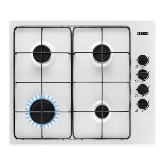
PRODUCT DESCRIPTION COOKING SURFACE LAYOUT Rapid burner Semi-rapid burner Auxiliary burner Control knobs CONTROL KNOB Symbol Description Symbol Description minimum gas supply no gas supply / off position ignition position / maximum gas supply DAILY USE BURNER OVERVIEW WARNING! Refer to Safety chapters. A. -
Page 12: Ignition Of The Burner
B. Burner crown CAUTION! In the absence of C. Ignition candle electricity you can ignite the burner D. Thermocouple without electrical device; in this case approach the burner with a flame, turn IGNITION OF THE BURNER the control knob counter-clockwise to maximum gas supply position and Always light the burner before you put push it down. -
Page 13: Care And Cleaning
DIAMETERS OF COOKWARE Diameter of cook- Use cookware with diameters Burner ware (mm) applicable to the size of burners. Semi-rapid 120 - 220 Diameter of cook- Burner Auxiliary 80 - 180 ware (mm) Rapid 180 - 260 CARE AND CLEANING 2. -
Page 14: Troubleshooting
TROUBLESHOOTING WARNING! Refer to Safety chapters. WHAT TO DO IF... Problem Possible cause Remedy There is no spark when you try The hob is not connected to an Check if the hob is correctly to activate the spark generator. electrical supply or it is con- connected to the electrical nected incorrectly. -
Page 15: Technical Data
LABELS SUPPLIED WITH THE ACCESSORIES Stick the adhesive labels as indicated below: MOD. MOD. MOD. TYPE PROD.NO. IP20 PROD.NO. PROD.NO. SER.NO. 0049 SER.NO SER.NO 03 IT DATA DATA MADE IN ITALY A. Stick it on Guarantee Card and send this part C. -
Page 16: Energy Efficiency
OTHER TECHNICAL DATA Gas original: G20 (2H) 20 mbar 8 kW TOTAL POW- Gas replace- G30 (3+) 28-30 mbar 567 g/h ment: G31 (3+) 37 mbar 557 g/h Electric supply: 220-240 V ~ 50-60 Hz 3 core flexible cable with non rewireable plug fitted with a 3 amp cartridge fuse Appliance cate- II2H3+ gory:... -
Page 17: Environmental Concerns
Left front - Rapid 58.0% Right front - Auxiliary not applicable Energy efficiency for the gas hob 57.7% (EE gas hob) Model identification ZGNN640W Type of hob Built-in hob Number of gas burners Left rear - Semi-rapid 59.4% Right rear - Semi-rapid 56.3%... - Page 20 WWW.ZANUSSI.COM/SHOP...