Advertisement
Table of Contents
- 1 Table of Contents
- 2 Electrostatic Discharge Sensitive (ESDS) Device Handling
- 3 Specifications
- 4 Technical Description
- 5 Disassembly/Assembly Procedures
- 6 Test Procedures
- 7 Part List Notes
- 8 PCB Identification
- 9 Main Part List
- 10 Electrical Part List
- 11 Speaker Part List
- 12 Technical Information
- 13 Technical Information
- Download this manual
Advertisement
Table of Contents

Summary of Contents for Bose 1401 I Series
- Page 1 ® ® ™ 1201, 1401 Series I and II ® Direct Reflecting Car Stereo Speaker System Model 1201 1401 Series I 1401 Series II Service Manual © 1998 Bose Corporation Part Number 122762 REV 01...
-
Page 2: Table Of Contents
BOSE ® CORPORATION WHICH IS BEING FURNISHED ONLY FOR THE PURPOSE OF SERVICING THE IDENTIFIED BOSE PRODUCT BY AN AUTHORIZED BOSE SERVICE CENTER OR OWNER OF THE BOSE PRODUCT, AND SHALL NOT BE REPRODUCED OR USED FOR ANY OTHER PURPOSE. -
Page 3: Electrostatic Discharge Sensitive (Esds) Device Handling
ELECTROSTATIC DISCHARGE SENSITIVE (ESDS) DEVICE HANDLING This unit contains ESDS devices. We recommend the following precautions when repairing, replacing, or transporting ESDS devices: • Perform work at an electrically grounded work station. • Wear wrist straps that connect to the station or heel straps that connect to conductive floor mats. -
Page 4: Specifications
SPECIFICATIONS Power Output: 1401 four channels 100 Watts continuous into 0.45 Ohms 1201 two channels 50 Watts continuous into 0.45 Ohms Individual Amplifiers: 25 Watts continuous into 0.45 Ohms resistive loads from 40 Hz to 17 kHz with less than .09% THD with 14.4 Volts DC IM Distortion: 0.4% at 20 Watts output ±... - Page 5 SPECIFICATIONS Power Supply Tolerance: Will operate without noticeable performance defects between 10.5 and 16.5 Volts DC Temperature Tolerance: -25° C (-13° F) to +60° C (+140° F) Dimensions: 10" W x 5" D x 2 1/2 " H 1401 I and II 8 1/8"...
-
Page 6: Technical Description
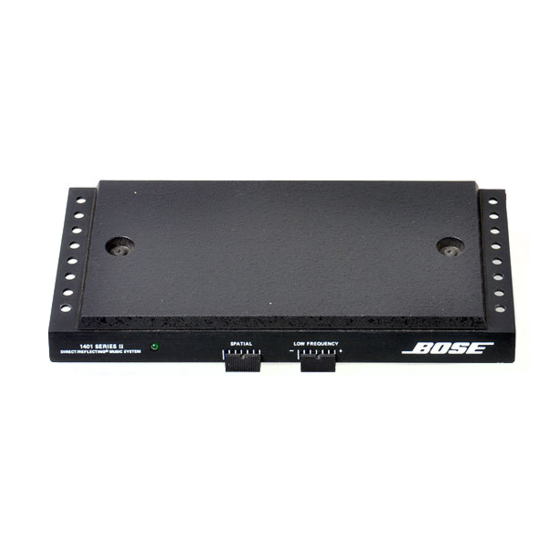
6"x 9" speakers. ® The Bose 1401™ II Booster/Equalizer incorporates unique circuitry that is different from other auto amplifier designs. We ask that you take the time to read this technical description before attempting to service the 1401, and 1401 series II, as it will aid you in the repair process. - Page 7 TECHNICAL DESCRIPTION The 1401™II has four separate power amplifiers. Each power amplifier receives a summed signal from the common bass buss, and the mid and high frequency information from the Spatial Control™ slider. Using all four speakers to reproduce the bass frequencies provides full rich bass response while directing the other frequencies to the appropriate, left/right/front/back speakers, to maintain proper spatial characteristics.
- Page 8 1201 Technical Description ® The Bose 1201 Booster/Equalizer is a two speaker system similar to the 1401™ II. In gen- eral, the same troubleshooting rules apply to both units. The RCA and high level inputs are the same, as well as the connectors for the power and speakers.
- Page 9 TECHNICAL DESCRIPTION Figure 1. 1401 Block Diagram...
- Page 10 TECHNICAL DESCRIPTION Figure 2. 1401 II Block Diagram...
-
Page 11: Disassembly/Assembly Procedures
DISASSEMBLY/ASSEMBLY PROCEDURES Note: The following procedure is for the 4.2 Secure the top cover to the PCB 1401™ series II. The disassembly for the assembly using the three screws removed 1401 series I is the same with the excep- in procedure 3.3. tion of the earlier units. - Page 12 DISASSEMBLY/ASSEMBLY PROCEDURES 1201 Disassembly/Assembly Procedure 3.3 Remove the four screws securing the 1. Bottom Cover Removal PCB to the heat sink. 1.1 Remove the four screws located at the 3.4 Lift the PCB assembly off of the heat back (connector end) of the unit and the sink.
-
Page 13: Test Procedures
TEST PROCEDURES Test Procedure Set-Up (refer to the diagram below) 1401 I Speaker Wire Connection Caution: Before connecting the Booster/ Left Front Equalizer to the power supply, test the 1. Output: White/Yellow zener diode for a possible short by check- 2. - Page 14 TEST PROCEDURES 3. Spatial Control, High Frequency, and Note: The Booster/Equalizer should be Rear Switch Control Test operated and tested using a 100 Ohm load for each of the speaker outputs until the 3.1 Apply a 35 mV 15 kHz signal to the low unit functions properly.
- Page 15 TEST PROCEDURES 5. High Level Input Test 5.1 Apply a 1 kHz signal to the high level inputs. 5.2 Increase the input level until the output just begins to clip. The signal input reading should be approximately 2.75 Volts. 6. Protection Circuit Test Note: This test is for the 1401 II and the 1201 only.
-
Page 16: Part List Notes
PART LIST NOTES 1. This part is not normally available from Customer Service. Approval from the Field Service Manager is required before ordering. 2. The individual parts located on the PCBs are listed in the Electrical Parts Lists. 3. The reference designators in bold are found in the 1401™ PCB's with serial numbers below 5,000. - Page 17 Figure 3. 1401™, 1401 II, and 1201 Exploded View...
- Page 18 Figure 4. Main Part List Exploded View...
-
Page 19: Main Part List
MAIN PART LIST (Refer to Figures 3 and 4) Item Number Description Part Number Q t y . Note Dpdt Slide Switch 112553 1 or 2 4 Pin Connector 112738-4 Phone Jack 110386 Heat Sink, Driver Transistor 112733 Main Heat Sink 114276 1401 Screw, #4-40 x .25L Self Tap TORX... -
Page 20: Electrical Part List
ELECTRICAL PART LIST 1401 Series I Resistors Reference Designator Description Part Number Note 1K, 1/2W, 5%, CF 113777-102 R2, 3, 70, 90 150K, 2%, CF 107182-154 10 Ohm, 5%, CF 103774-100 R10, 40, 77, 83 5.6K, 2%, CF 113773-562 R11, 21, 31, 41 910 Ohm, 5%, CF 107183-911 R12, 42... - Page 21 ELECTRICAL PART LIST 1401 Series I Resistors (continued) Reference Designator Description Part Number Note 330K, 5%, CF 113774-334 R158 12K, 2%, CF 113773-123 R201, 208 47K, 5%, CF 113774-473 R202 220K, 5%, CF 113774-224 R203, 209 22K, 5%, CF 113774-223 R205 1 Ohm, 5%, CF 113774-103...
- Page 22 ELECTRICAL PART LIST 1401 Series I Transistors Reference Designator Description Part Number Note Q11, 21, 31, 41 NSD U51, PNP 112998 Q12, 22, 32, 42, 53, 202 MPS U01, NPN 112999 Q13, 23, 33, 43 D44H2 119893 Q14, 24, 34, 44 D45H2 119892 Q15, 25, 35, 45, 50, 201...
- Page 23 ELECTRICAL PART LIST 1401 Series II and 1201 Resistors Reference Designator Description Part Number Note R11, 12, 21, 22, 31, 32, 41, .47 Ohm, 5%, CF 108904 R13, 14, 23, 24, 33, 34, 43, 27 Ohm, 5%, CF 117704-1212705 44, 125, 126, 225, 226 R15, 25, 35, 45, 129, 229 220 Ohm, %5, CF 117704-1212215...
- Page 24 ELECTRICAL PART LIST 1401 Series II and 1201 Resistors (continued) Reference Designator Description Part Number Note R116, 121-123, 503, 504, 47K, 5%, CF 117704-1214735 R117, 126-128, 301, 303, 10K, 5%, CF 117704-1211035 401, 403, 507, 510, 604, R118 360 Ohm, 5%, CF 117704-1223615 R118 2.32K, 1%, MF, 1/4W...
- Page 25 ELECTRICAL PART LIST 1401 Series II and 1201 Capacitors Reference Designator Description Part Number Note C11, 21, 31, 41, 113, 213 1000uF, 16V, Electrolytic 120970 C12, 13, 22, 23, 32, 33, 42, 1800pF, 50V, 10%, Disc 119017-182 43, 110, 111, 210, 211 C14, 34 43pF, 50V, 10%, Tubular 117245-430107...
-
Page 26: Speaker Part List
SPEAKER PART LIST (Refer to Figure 5) Item Number Description Part Number Q t y . Note Plain Grille Assy, Grey 112023 Plain Grille Assy, Black 119548 Escutcheon (For Deluxe Grille) 1401 111769 4.5" Driver 119179 119511 Escutcheon (For Deluxe Grille)1401 II Masonite Gasket 112410 Deluxe Grille - Reflector only... -
Page 27: Technical Information
TECHNICAL INFORMATION... -
Page 28: Technical Information
TECHNICAL INFORMATION Trouble Shooting Guide Symptom Check Draws current: Check D55, series II; Check D2, series I No left or right output: Check electrolytic caps at the input to U51 or at the output of U52 for series I and U53 for series II. Replace all caps with a silver colored can. - Page 30 SPECIFICATIONS AND FEATURES SUBJECT TO CHANGE WITHOUT NOTICE ® ® Bose Corporation The Mountain Framingham Massachusetts USA 01701 P/N 122762 REV. 01 12/98 FOR TECHNICAL ASSISTANCE OR PART ORDERS, CALL 1-800-367-4008...
Need help?
Do you have a question about the 1401 I Series and is the answer not in the manual?
Questions and answers