Advertisement
Quick Links
INSTALLATION AND OPERATION MANUAL
MANUAL DE INSTALACIÓN Y FUNCIONAMIENTO
INSTALLATIONS- UND BETRIEBSHANDBUCH
MANUEL D'INSTALLATION ET DE FONCTIONNEMENT
MANUALE D'INSTALLAZIONE E D'USO
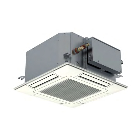
INDOOR UNITS SYSTEM
RAI-E50YHA, RAI-E60YHA
MANUAL DE INSTALAÇÃO E DE FUNCIONAMENTO
INSTALLATIONS- OG BETJENINGSVEJLEDNING
INSTALLATIE- EN BEDIENINGSHANDLEIDING
INSTALLATION- OCH DRIFTHANDBOK
ΕΓΧΕΙΡΙΔΙΟ ΕΓΚΑΤΑΣΤΑΣΗΣ ΚΑΙ ΛΕΙΤΟΥΡΓΙΑΣ
4-way cassette - R32
Advertisement

Related Manuals for Hitachi RAI-E50YHA


Summary of Contents for Hitachi RAI-E50YHA
- Page 1 INSTALLATION AND OPERATION MANUAL INSTALLATIONS- OG BETJENINGSVEJLEDNING MANUAL DE INSTALACIÓN Y FUNCIONAMIENTO INSTALLATIONS- UND BETRIEBSHANDBUCH INSTALLATIE- EN BEDIENINGSHANDLEIDING MANUEL D’INSTALLATION ET DE FONCTIONNEMENT INSTALLATION- OCH DRIFTHANDBOK MANUALE D’INSTALLAZIONE E D’USO ΕΓΧΕΙΡΙΔΙΟ ΕΓΚΑΤΑΣΤΑΣΗΣ ΚΑΙ ΛΕΙΤΟΥΡΓΙΑΣ INDOOR UNITS SYSTEM 4-way cassette - R32 RAI-E50YHA, RAI-E60YHA...
- Page 2 Specifikationerna i den här handboken kan ändras utan föregående meddelande för att HITACHI ska kunna leverera de senaste innovationerna till kunderna. Vi på HITACHI gör allt vi kan för att se till att alla specifikationer stämmer, men vi har ingen kontroll över tryckfel och kan därför inte hållas ansvariga för den typen av fel.
- Page 3 C A U T I O N This product shall not be mixed with general house waste at the end of its life and it shall be retired according to the appropriated local or national regulations in a environmentally correct way. Due to the refrigerant, oil and other components contained in Air Conditioner, its dismantling must be done by a profes- sional installer according to the applicable regulations.
- Page 4 DANGER – Hazards or unsafe practices which COULD result in severe personal injuries or death. PELIGRO – Riesgos o prácticas poco seguras que PODRÍAN producir lesiones personales e incluso la muerte. GEFAHR – Gefährliche oder unsichere Anwendung, die zu schweren Körperverletzungen oder zum Tod führen kann. DANGER –...
- Page 5 English V O R S I C H T Dieses Symbol zeigt an, dass dieses Gerät ein entzündbares Kälte- WA R N I N G mittel verwendet. Bei einem Kältemittelaustritt besteht die Gefahr der Entzündung, wenn das Kältemittel in Kontakt mit einer äußeren BURST HAZARD Zündquelle kommt.
- Page 6 This product contains biocidal substances according to EU Reg. 528/2012 Este producto contiene sustancias biocidas según el Reg. UE 528/2012 Dieses Produkt enthält Biozide nach EU Verordnung 528/2012 Conformément à la Reg UE 528/2012, ce produit contient des substances biocides Questo prodotto contiene sostanze biocidi ai sensi del Reg.
- Page 7 INDEX INDEX 1 GENERAL INFORMATION 1 INFORMATIONS GÉNÉRALES 2 SAFETY 2 SÉCURITÉ 3 IMPORTANT NOTICE 3 REMARQUE IMPORTANTE 4 BEFORE OPERATION 4 AVANT LE FONCTIONNEMENT 5 MAINTENANCE 5 MAINTENANCE 6 NAME OF PARTS 6 NOMENCLATURE DES PIÈCES 7 BEFORE INSTALLATION 7 AVANT L'INSTALLATION 8 INDOOR UNIT INSTALLATION 8 INSTALLATION DE L’UNITÉ...
- Page 8 1.1 GENERAL NOTES No part of this publication may be reproduced, copied, filed HITACHI makes every effort to offer correct, up-to-date or transmitted in any shape or form without the permission of documentation. Despite this, printing errors cannot be controlled Johnson Controls-Hitachi Air Conditioning Spain, S.A.U.
- Page 9 2.2 ADDITIONAL INFORMATION ABOUT SAFETY D A N G E R • HITACHI is not able to foresee all the circumstances which may • Do not use sprays, such as insecticides, varnishes or enamels or any result in a potential danger.
- Page 10 IMPORTANT NOTICE During operation: • Avoid an extended period of exposure to a direct air flow. Low temperature solder alloys, such as lead/tin alloys, are not acceptable for pipe connections. • Do not insert fingers, rods or other objects into the air outlet or inlet.
- Page 11 IMPORTANT NOTICE or explosion, including cigarette smoking, must be kept damage. The check shall also take into account the effect sufficiently far away from the working area, since refrigerant of ageing or continual vibration from sources such as may be released to the surrounding space. The area around compressors of fans.
- Page 12 Cylinders shall be kept upright. • Replace components only with parts specified by HITACHI. Ensure that the refrigeration system is earthed prior to Other parts may result in the ignition of refrigerant in the charging the system with refrigerant.
- Page 13 MAINTENANCE 4.2 EFFICIENT USE OF COOLING AND HEATING COOLING HEATING 1 Air flow direction: the appropriate air outlet angle is approx. 1 Air flow direction: the appropriate air outlet angle is approx. 35º. If the cooling is not sufficient, change the air flow 60º.
- Page 14 MAINTENANCE 5.1 DAILY MAINTENANCE 5.1.1 Cleaning Air Filter 5.1.2 Removing, attaching and cleaning air inlet grille 1 Open the air inlet grille. N O T E While sliding the knobs on both side of the air inlet grille in the arrow direction, open the air inlet grille. •...
- Page 15 Motion sensor (optional accessory) Refrigerant liquid pipe connection (with Øb flare nut) Drain pipe connection (VP25) (mm) Drain discharge mechanism Model Float switch RAI-E50YHA 12,7 6,35 RAI-E60YHA 12,7 6,35 N O T E Regarding the refrigerant cycle drawings and diagrams, refer to Technical Catalogue.
- Page 16 BEFORE INSTALLATION 7 BEFORE INSTALLATION 7.1 TRANSPORTATION AND HANDLING 7.1.2 Handling of indoor unit C A U T I O N • Do not put any material on the product. D A N G E R • Do not step on the product. Do not put any foreign material into the indoor unit and check to 7.1.1 Transportation of indoor unit ensure that no foreign material exists in the indoor unit before...
- Page 17 Accessory Q'ty Purpose Accessory Q'ty Purpose INDOOR UNIT INSTALLATION Accessory Q'ty Purpose For Adjusting Space of False Checking Scale For Adjusting Space of False Checking Scale For Adjusting Space of False Checking Scale Ceiling Opening and (Cut and Take Out it Ceiling Opening and (Cut and Take Out it Ceiling Opening and...
- Page 18 INDOOR UNIT INSTALLATION 8.2 INITIAL CHECK Suspension bolt for Suspension Bolt • Install the indoor unit with a proper clearance around it indoor unit for Indoor Unit paying careful attention of installation direction for the piping, wiring and maintenance working space, as shown below. •...
- Page 19 INDOOR UNIT INSTALLATION 8.3 INSTALLATION Opening of false ceiling and location of For wooden beam: suspension bolts Install the indoor unit to the tie beam (for single-storied building) • Determine the final location and installation direction of or to the second floor girder (for two-storied building), and use the indoor unit paying attention to the space for the piping, sufficiently strong squared timber shown below.
- Page 20 INDOOR UNIT INSTALLATION b. The positional relation between the indoor unit and the 4 Mounting indoor unit air panel (optional) is shown in figure below: a. Lift up the indoor unit by a hoist, and do not apply any (mm) force to the drain pan (the air outlet portions and the 4-positions of suspension bolts (M10 or W3/8) drain pan portion).
- Page 21 INDOOR UNIT INSTALLATION b. For false ceiling without opening 7 The upper surface of the unit is protected by corrugated cardboard to prevent the unit from being damaged by If there is no opening in the existing false ceiling, provide spatter, etc.
- Page 22 Model Gas Pipe Liquid Pipe Attach a cap or put a plastic bag Attach a ca Cap or plastic bag RAI-E50YHA over the pipe end. bag over th Ø12.7 (1/2) Attach a cap or put a plastic bag Ø6.35 (1/4)
- Page 23 REFRIGERANT PIPING 9.3 PIPING CONNECTION SIZE Perform flaring work according to the figures and tables below: Required tightening torque Flare pipe dimensions Pipe Size Tightening Torque Ø6.35 mm (1/4) 14 - 18 (N-m) mm (in.) Ø9.52 mm (3/8) 34 - 42 (N-m) ∅...
- Page 24 DRAIN PIPING Insulate each flare connection without gap with field-supplied If coating the optional air panel with a forming agent insulations to prevent dew condensation. Then insulate each (recommended Gupoflex) after installation, make sure that the refrigerant pipe as well. forming agent does not contact it.
- Page 25 DRAIN PIPING 6 Insert the drain hose completely. If it is not inserted properly, • Do not apply an excessive force to the drain pipe connection. It could cause a damage. or if it is twisted, water leakage may occur. ...
- Page 26 DRAIN PIPING Drainage and water leakage check Simplified Operation of Drain-up Mechanism After performing drain piping work and the electrical wiring and The following is the simplified operation procedure of the drain- before installing the air panel, check to ensure that water flows up mechanism.
- Page 27 ELECTRICAL WIRING 11 ELECTRICAL WIRING 11.1 GENERAL INFORMATION D A N G E R C A U T I O N • Turn off the main power switch to the indoor unit and the • Use twisted shielded pair cable or shield pair cable for transmission outdoor unit before electrical wiring work or a periodical check wires between the indoor and the outdoor units, for the control cable is performed.
- Page 28 ELECTRICAL WIRING 11.3 POSITION OF ELECTRICAL WIRING CONNECTION C A U T I O N Connect the cable for the optional remote control switch or the optional extension cable to the terminals inside the electrical box • Ensure that the wiring terminals are tightened securely with the through the connecting hole in the cabinet.
- Page 29 IEC 60335-1 IEC 60335-1 Check to ensure that the stop valves of the outdoor unit 1~220-240V RAI-E50YHA are fully opened, and then start the system. 2.5mm 1.5mm RAI-E60YHA 50/60Hz Check to ensure that the switch on the main power source has been ON for more than 12 hours, to warm the compressor oil by the crankcase heater.
- Page 30 This air panel is applicable to the following indoor unit model: Air panel Indoor unit model P-AP56NAM RAI-E50YHA, RAI-E60YHA 12.2 TRANSPORTATION AND HANDLING 1 Transport the air panel without unpacking as close to the In addition, if the air panel is placed with the surface installation location.
- Page 31 INSTALLATION OF OPTIONAL AIR PANEL: P-AP56NAM The operation is continued even if there is no person in a room. Pay attention that the detecting function is decreased if the lens for sensor smudges. Object such as a curtain or a leafy plant is swaying in the wind in the detecting area.
- Page 32 INSTALLATION OF OPTIONAL AIR PANEL: P-AP56NAM 4 Remove the corner pocket covers. 8 Fix the air panel by the four fixing screws “A” and “B” (each 2 portions) securely as shown in the figure. The corner pocket covers can be removed pulling Ⓐ part toward the arrow direction in the figure below.
- Page 33 INSTALLATION OF OPTIONAL AIR PANEL: P-AP56NAM 10 Attachment of corner pocket cover N O T E Attach the corner pocket covers (4 portions) after the air • Firmly tighten the long screws. If the long screws are tightened insufficiently, it may cause the following failures. panel is mounted completely.
- Page 34 INSTALLATION OF OPTIONAL AIR PANEL: P-AP56NAM 12.5 ELECTRICAL WIRING C A U T I O N • Perform securely the electrical wiring work. If the electrical work is not completed, heat generation at the connection, a fire or an electric shock may occur.
- Page 35 OPTIONAL PART 12.6 TEST RUN 1 After completing the installation of the air panel, the test run Do not move the louvre by hand. If moved, the auto-swing should be performed. mechanism will be damaged. 2 Perform the checking work for the louvre during the test run. 12.7 ADJUSTING LOUVRES Louvre Louver...