Table of Contents
Advertisement
Quick Links
- 1 Product Overview
- 2 Make Sure the Bvs Hardware Is Configured Properly
- 3 Make Sure the Scm-600 Is Turned on and Connected
- 4 Make Sure the Hardware Is Communicating with the Software
- 5 Ensure that Settings and Readings Are Correct
- 6 Enable Remote Communication
- 7 Adding Your Batteries to the System
- Download this manual
Advertisement
Table of Contents

Related Manuals for BTECH S5 BATTERY VALIDATION SYSTEM SCM-600


Summary of Contents for BTECH S5 BATTERY VALIDATION SYSTEM SCM-600
- Page 1 Battery Validation Manager Software & Battery Validation System Operating Manual • Rockaway, NJ 07866, U.S.A. www.btechinc.com...
- Page 2 BTECH Inc. takes pride in the quality of its new documentation. However, technical inaccuracies, typographical errors and editorial omissions do occur from time to time. Although the documentation is provided “as is,” and BTECH Inc. disclaims all direct, indirect or consequential damages that may result from such errors, please let BTECH Inc. know immediately if you discover inaccuracies, errors or omissions.
-
Page 3: Table Of Contents
Table of Contents Product Overview ................5 Product Warranty................6 A. Hardware Warranty......................6 B. Software Warranty....................... 6 C. Entitlement During the Applicable Warranty Period ............6 Installing the Software ..............9 1. Install the BVM Software ..................... 9 2. Activate the BVS Observer....................11 3. - Page 4 S5 Battery Validation System...
-
Page 5: Product Overview
1989. Today, with over 3000 systems installed worldwide, BTECH is the undisputed leader in the battery monitoring industry with experience that is unmatched. BTECH has a staff of engineers and technicians supporting the product at our headquarters in Morris Plains, NJ, and has built a network of trained service technicians across North America, Asia, Europe, Africa and the Middle East. -
Page 6: Product Warranty
Should BTECH Factory Service determine, during the course of providing support hereunder, that the End User may benefit from the installation of a firmware patch, upgrade or software bug fix, if and when BTECH, at its sole discretion, develops and releases said firmware patch, or upgrade, or software bug fix, BTECH may make it available to the End User at no charge. - Page 7 Hardware Products during the above referenced periods: a. BTECH must be notified by End User prior to the return of said Product. Within ten (10) days of the date of said notification BTECH will provide End User with a valid Return Material Authorization Number (RMA).
- Page 8 End User. BTECH warranties shall not apply to any Product or Licensed Material which has been damaged as a result of, or subjected to, accident, neglect, misuse, abuse, vandalism, riot, war, acts of terrorism, negligence in transportation or...
-
Page 9: Installing The Software
Installing the Software INSTALLING THE SOFTWARE 1. Install the BVM Software ........9 3. Installing Drivers for USB Port on SCM-600..12 2. Activate the BVS Observer ........11 1. Install the BVM Software Action How to do it Picture Choose File>Exit from each program’s menu bar. Close all other programs on your computer. - Page 10 • Only for me 5 (Widespread access to the BVM program will not endanger your battery backup system.) The default location is C:\Program Files\BTECH\BVM 4.0\ Click on Next to continue. When prompted, select where to install the program files.
-
Page 11: Activate The Bvs Observer
The BVM CD is only required when installing order to activate BVM and activating BVS Observer. BVS Observer. From the Start menu, select Programs > BTECH > BVS Observer 4.1. If the Activate BVS Observer Start the BVS screen shown below does not appear Observer. -
Page 12: Installing Drivers For The Usb Port On Scm-600
3. Installing Drivers for the USB Port on SCM-600 Steps to Install USB Drivers Screen Shot For WINDOWS XP Installation from CD The drivers should be installed from the BVM Installation CD. If the CD is not available and the PC is connected to the Internet, the drivers can be installed via Windows Update. - Page 13 Installing the Software Steps to Install USB Drivers Screen Shot The Found New Hardware Wizard will again begin to install the next driver. Select the “No, not at this time” on the wizard and click the Next button. Select “Install from a list or specific location” and click the Next button. Select “Search for the best driver in these locations”...
- Page 14 Steps to Install USB Drivers Screen Shot For WINDOWS 2000 Installation from CD Screen Shot The drivers should be installed from the BVM Installation CD. Connect the USB port on the SCM-600 to a free USB port on the PC or hub connected to a USB port on the PC.
- Page 15 Installing the Software Steps to Install USB Drivers Screen Shot When the installation of the first driver is complete, click the Finish button to continue. The Found New Hardware Wizard will again begin to install the next driver. Click the Next button to continue. Select “Search for a suitable driver for my device”...
- Page 16 Steps to Install USB Drivers Screen Shot When the wizard finishes installing the driver, click the Finish button. The BVM will now be able to communicate with the SCM-600 via the USB port. S5 Battery Validation System...
-
Page 17: Starting Up
Starting Up STARTING UP 1. Make sure the BVS hardware is configured 4. Make sure the hardware is communicating with the properly..............17 software ..............21 2. Make sure the SCM-600 is turned on and 5. Ensure that settings and readings are correct ..28 connected ..............19 6. - Page 18 Action How to do it Picture Make sure the load current leads are Make sure each LCL wire contains a fuse. connected. Make sure each plug on the SCM-600, VM24, and CM-2 is inserted firmly and has all its wires installed.
-
Page 19: Make Sure The Scm-600 Is Turned On And Connected
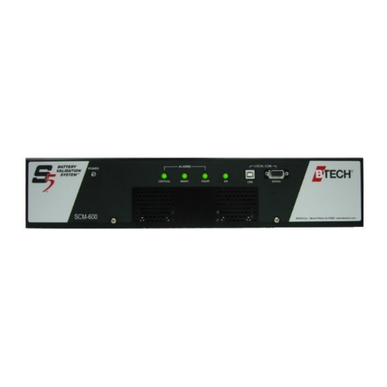
Starting Up 2. Make sure the SCM-600 is turned on and connected Action How to do it Picture • Flip the POWER toggle switch on back the SCM-600. • Flip the ON toggle switch on the from of the SCM-600. The ON light should come on. Turn on the SCM- 600. -
Page 20: Add The Battery File(S) Included On Your Bvm Software Cd
... Action How to do it Picture From the Start menu, select Programs > BTECH > Battery Validation Manager 4.1 Start the BVM program. If prompted, read the pop-up note telling you how to add location data files and controller configuration files. -
Page 21: Make Sure The Hardware Is Communicating With The Software
Starting Up 4. Make sure the hardware is communicating with the software Action How to do it Picture In the Location List window, click on a location file, then click OK. Open a location file. From the BVM software menu bar, select Communications>... - Page 22 Action How to do it Picture From the Communications - S5 Test window, Check system click on Advanced, then click on System configuration Configuration. a. From the System Configuration window, click on Module Config. (“Module” refers to a VM-24.) Diagnose existing errors.
- Page 23 Starting Up Action How to do it Picture iii. Select the module you want to view. In this example, Module 1 will be used. iv. In the Controller Module Diagnostics window, look for: 0.00 voltage: May indicate a disconnected lead or missing VSL fuse. 0.01 voltage: Could be normal, if voltage is being read over a battery interconnect (battery bar or strap)
- Page 24 Action How to do it Picture Re-establish a. From the System Configuration window, click communications. Clear Memory, then select Relearn Connections. b. When prompted to clear the alarms, click Yes. c. In the Communications window, look at the alarm LEDs. They should be off. If one of them is not off, either the BVM system is not installed correctly, or there is a problem with one of the batteries.
- Page 25 Starting Up Action How to do it Picture In the Controller Module Diagnostics window, click on the module that has the alarm in the BVM file. In this example, module 12 will be used. Select the module to view. a. Look for leads with an unusual voltage reading.
- Page 26 Action How to do it Picture Go to the battery cells that match the modules having errors. Check for disconnected leads, wires, or plugs, missing fuses, or crossed leads. Fix any problems found. Fix the error. Example of disconnected lead on left; problem solved on right Missing fuse on left;...
- Page 27 Starting Up Action How to do it Picture When prompted to proceed, click Yes. Proceed with the relearn process. In the Communication - S5 Test window, see if the alarm light now turns off. If it does, the alarm is cleared. If it does not, repeat steps 11 - 17.
-
Page 28: Ensure That Settings And Readings Are Correct
If you need further instructions on how to set date occurred. and time on your computer, refer to the Windows help file. a. From the Start menu, select Programs > BTECH > Battery Validation Manager 4.0 If not already running, start BVM, open a *.bvm file and establish local communications. - Page 29 Starting Up Action How to do it Picture c. From the BVM software menu bar, select Communications> Establish Local (cont.) Communication with Controller. d. From the Local Communication Settings window, select the port that the communications cable is selected to, then click OK. The Communications window will appear.
- Page 30 Action How to do it Picture Enable the BVM to display individual a. From the menu bar, select Settings>System battery string Settings... information. b. From the Software System Settings window, select the System Current Measurements: Current Measured Per String” radio button. S5 Battery Validation System...
- Page 31 Observe the real-time graphs to see if they change over time. If the graphs do not appear or do not change, call BTECH Tech Support. c. When finished, click Disable Real-Time to close the graphs. Operating Manual...
- Page 32 For each column of readings, subtract the lowest value from the highest value. Take the result and divide this by the average value. If the result is 0.10 or more, call BTECH Tech Support. Example (from next page): Highest reading in Unit 2 column: 3.07...
- Page 33 Starting Up Action How to do it Picture Unit Impedance Readings, String 1 Unit Impedance Readings (Example) Next-to- Next-to- Measurement Unit 2 last unit in Measurement Unit 2 last unit string in string Reading 1 Reading 1 3.07 2.94 Reading 2 Reading 2 3.06 2.92...
- Page 34 If you get an error message after clicking the Auto Multiplier Setup button, you will need to generate the multipliers manually. Call BTECH Tech Support for assistance. d. Wait for the process to finish. Depending upon...
- Page 35 Starting Up Action How to do it Picture Gather system a. From the Communications window, click measurements and Measurements: Perform. The green Measuring check for LED will light up. inconsistent readings, then make repairs to the battery system as needed. This is the longest process in setting up your battery system,...
- Page 36 The graph below represents a battery system with inconsistent voltage readings. With battery systems that have not had regular maintenance, this is not uncommon. Debugging must occur to find out why the voltage readings are so erratic. Contact BTECH for assistance or your battery service provider for service.
- Page 37 Starting Up Action How to do it Picture a. In the Location List, highlight a measurement that is close to the average of the values shown. Define the standard for impedance. This is needed so the BVM will know what abnormal impedance looks like.
- Page 38 Action How to do it Picture f. In the Communication window, click (cont.) Controller Settings. g. In the Controller Settings window, go to the Impedance Analysis field and change Average to Initial. h. Click OK when done. S5 Battery Validation System...
-
Page 39: Enable Remote Communication
Starting Up 6. Enable remote communication Action How to do it Picture Plug an Ethernet or phone line into the back of the SCM controller, then make sure the wire is connected to your server or computer. Install TCPIP or phone wiring from the SCM controller to your server/... -
Page 40: Adding Your Batteries To The System
Software ..............45 Battery information is contained in battery location files. These might be created for you by BTECH and included on your BVM installation CD. If so, you would have added them during the intial setup process in the previous chapter. - Page 41 Adding Your Batteries to the System Action How to do it Picture From the Save As window, browse to select a location to save the file, type the filename (ending in *.bvm), then click Save. Name the file. a. Type a user name and password in the related fields.
- Page 42 In the Software Location Settings field, enter the following data. This data will be seen by the BTECH help desk if you ask for assistance. • Location ID: This must match the number of the SCM controller. It can be any number you wish.
- Page 43 Adding Your Batteries to the System Action How to do it Picture a. In the Software System Settings window, enter the following data (the rest is automatically generated): Battery Configuration: • Units Per String: The number of voltage measurements per string (the number of intervals between VSL leads) •...
- Page 44 Action How to do it Picture a. In the Software Limit Settings window, in the Apply to Unit(s) field, select a unit that has a thermistor attached, then in the Temperature Sensor field, select the ordinal number (e.g. 1st, 2nd, 3rd, etc.) of the thermistor that goes with it.
-
Page 45: Adding New Battery Location Files To The Bvm Software
Adding New Battery Location Files to the BVM Software Action How to do it Picture From the Start menu, select Programs > BTECH > Battery Validation Manager 4.0 If it is not already open, start the BVM program. 1 In the Location List window, click on Add Location to List. - Page 46 How to do it Picture Make sure the WIBU Plug the WIBU key into any USB port on your key is plugged in. computer. From the Start menu, select BTECH, then select BVS Observer Start the BVS Observer program. S5 Battery Validation System...
- Page 47 Checking Batteries for Problems Action How to do it Picture 1 In the main window, click on the + sign. 2 When prompted, browse for the battery location files. The default location for battery location files is C:\BVM4Data\. 3 Click on Open when done. Add the battery location file(s).
- Page 48 Action How to do it Picture Enter the e-mail addresses which a. From the menu bar, select Locations > Email should receive alarm Alarm Settings. messages. b. In the Email Settings window, click on the Enable check box to select it. c.
- Page 49 Looking for Battery Alarms Action How to do it Picture a. From the Start menu, select Programs > BTECH > Battery Validation Manager 4.0 If it is not already open, start the BVM program and look at the battery location file.
- Page 50 Action How to do it Picture b. A graphical representation of your battery system will appear. • A green rectangle indicates on OK battery cell. (cont.) • An orange rectangle indicates a battery cell that needs attention because its readings have exceeded maintenance limits.
- Page 51 However, if you want to see more detail, you can spread the range over a greater area. Action How to do it Picture a. From the Start menu, select Programs > BTECH > Battery Validation Manager 4.0 If not already running, start BVM, open a *.bvm file and establish communications.
- Page 52 Action How to do it Picture a. In the Communications window, click Go to the Controller Advanced>> to display the lower buttons. Settings window. b. Click the Controller Settings button. a. From the Controller Settings window, click on the Controller Measurement Setup tab. b.
- Page 53 Action How to do it Picture a. From the Start menu, select Programs > BTECH > Battery Validation Manager 4.0 If not already running, start BVM, open a *.bvm file and establish communications.
- Page 54 Action How to do it Picture a. In the Communications window, click Go to the Controller Advanced>> to display the lower buttons. Settings window. b. Click the Controller Settings button. From the Controller Settings window, click on the Unit Limits tab to select the limit set for each See how many units unit.
- Page 55 Viewing Battery Measurements Action How to do it Picture a. From the Start menu, select Programs > BTECH > Battery Validation Manager 4.0 If not already running, start BVM, open a *.bvm file. b. In the Location List window, click on a location file, then click OK. A *.bvm file will open, showing battery measurements.
- Page 56 BVM. Action How to do it Picture a. From the Start menu, select Programs > BTECH > Battery Validation Manager 4.0 If not already running, start BVM, open a *.bvm file.
- Page 57 Viewing Battery Activity Action How to do it Picture Double-click on a discharge reading in the upper window to see a graph of the series of readings for the View the trend of entire duration of battery performance the discharge. during a discharge.
- Page 58 S5 Battery Validation System...
Need help?
Do you have a question about the S5 BATTERY VALIDATION SYSTEM SCM-600 and is the answer not in the manual?
Questions and answers