Table of Contents
Advertisement
Quick Links
Advertisement
Table of Contents

Related Manuals for SEPTENTRIO PolaRx5


Summary of Contents for SEPTENTRIO PolaRx5
- Page 1 PolaRx5 - PolaRx5e User Manual...
- Page 2 Thank you for choosing the PolaRx5. This user manual provides detailed instructions on how to use PolaRx5 and we recommend that you read it carefully before you start using the device. Please note that this manual provides descriptions of all functionalities of the PolaRx5 product family.
-
Page 3: Table Of Contents
External memory ..............13 3 Getting started with the PolaRx5 5 . - Page 4 LIST OF CONTENTS (POEL) ........... 42 RESERVE VENT OGGING...
-
Page 5: Physical And Environmental
..............90 NSTALLING OOLS Appendix G Connecting to the PolaRx5 using RxControl... -
Page 6: Pola Rx
1 Introduction 1.1 User Notices 1.1.1 CE Notice PolaRx5 receivers carry the CE mark and are as such compliant with the 2004/108/EC - EMC Directive and amendments, 2006/95/EC - Low Voltage Directive, both amended by the CE-marking directive 93/68/EC. With regards to EMC, these devices are declared as class B, suitable for residential or business environment. - Page 7 1.1. USER NOTICES 1.1.3 Safety information Statement 1: The power supply provided by Septentrio (if any) should not be replaced by another. If you are using the receiver with your own power supply, it must have a double isolated construction and must match the specifications of the provided power supply.
- Page 8 Further information can be found on our website or by contacting Septentrio’s Technical Support department. In case the PolaRx5 does not behave as expected and you need to contact Septentrio’s Technical Support department, you should attach a short SBF log file containing the support blocks and a Diagnostic Report of the receiver (see Section 5.3).
-
Page 9: Power Consumption
2 PolaRx5 overview 2.1 Hardware Specifications 2.1.1 Power Consumption The power consumption of the PolaRx5 depends on its configuration. The following settings directly influence the amount of power consumed: • The number of enabled GNSS frequency bands. For example, a receiver configured to track signals only in the L1 and L2 bands will consume less than a receiver configured to track in the L1, L2 and L5 bands. -
Page 10: Performance
2.1. HARDWARE SPECIFICATIONS 2.1.2 Physical and Environmental Size: 235 x 140 x 37 mm (length includes connectors and excludes WiFi antenna) Weight: 900 g Temperature Range: -40 to +65 ◦ C (operational) -40 to +85 C (storage) ◦ Certification: IP65, RohS, CE FCC Class B Part 15 2.1.3 Performance Time accuracy 1 PPS out... -
Page 11: Front Panel
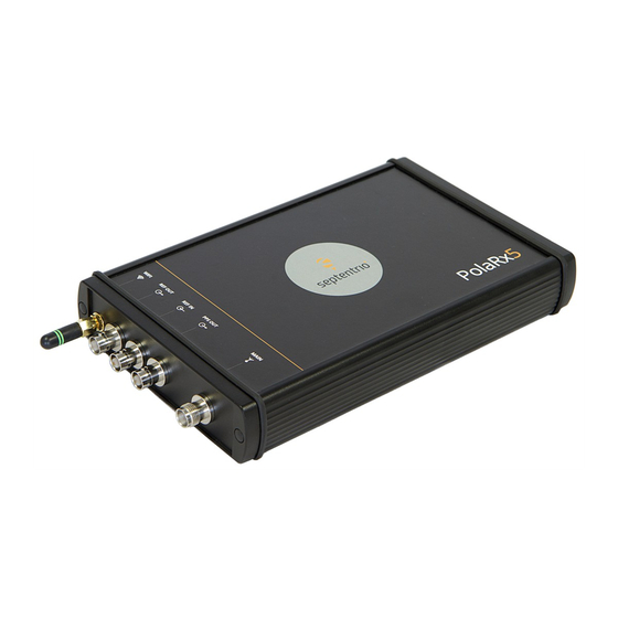
The front-panel layout of the PolaRx5 is shown in Figure 2-1. A description of the front-panel sockets on the PolaRx5 as well as their PIN assignments can be found in Appendix A. The cables available for use with the PolaRx5 are listed in Appendix D and the LED behaviour is described in Appendix E. -
Page 12: Powering The Receiver
WiFi is enabled. 2.2.6 Internal memory The PolaRx5 has a 16 GB Memory for internal data logging. Data can be logged in SBF, RINEX, BINEX, NMEA or RTCM-MSM format and may be retrieved via the ’Logging’ menu of the web... -
Page 13: External Memory
2.2. POLARX5 DESIGN 2.2.7 External memory The PolaRx5 can log data to an external memory device. More information on the recommended external device specifications can be found in Section 4.6.2. - Page 14 Before connecting an antenna, the orange front-panel tracking LED will be blinking fast indicating that the receiver is searching for satellites. After connecting an antenna that has a clear view of the sky, the PolaRx5 will start to track satellites and the tracking LED will start to...
-
Page 15: R X 5 Via The Web Interface
3.3. CONNECTING TO THE POLARX5 VIA THE WEB INTERFACE blink more slowly. The number of blinks between pauses indicates the number of satellites being tracked as described in Appendix E. 3.3 Connecting to the PolaRx5 via the Web Interface You can connect to the receiver on any device that supports a web browser using the receiver’s on-board Web Interface. - Page 16 The USB connection on the PolaRx5 functions as network adapter and the DHCP server running on the receiver will always assign the PolaRx5 the IP address 192.168.3.1. To connect to the PolaRx5, you can then simply open a web browser using the IP address 192.168.3.1 as shown in Figure 3-5.
-
Page 17: Over Wifi
When active, the red WiFi led will be lit. On your PC or tablet, search for visible WiFi signals: the PolaRx5 identifies itself as a wireless access point named ’PolaRx5-serial number’. The serial number of the PolaRx5 can be found on an identification sticker on the receiver housing. - Page 18 3.3. CONNECTING TO THE POLARX5 VIA THE WEB INTERFACE When your PC has connected to the PolaRx5 WiFi signal, you can open a web browser using the IP address 192.168.20.1 as shown in Figure 3-8. Figure 3-8: Connect to the Web Interface of the PolaRx5 over WiFi using the IP...
-
Page 19: Using The Ethernet Cable
‘PolaRx5-xxxxxxx’, where xxxxxxx are the 7 digits of the serial number of the GNSS Receiver Board (GRB) inside the PolaRx5. This number can also be found on an identification sticker on the receiver housing. You can then make a connection to the receiver using the web address http://PolaRx5-xxxxxxx. -
Page 20: As An Rtk Base Station
Set the position as static To work as a base station, the position of the PolaRx5 should be set to static. If not, the PolaRx5 will still work as a base station however the position of the rover may show more variation. - Page 21 4.1. HOW TO CONFIGURE THE POLARX5 AS AN RTK BASE STATION Figure 4-2: Setting the static position of the reference station antenna Click on ‘Ok’ to apply the new settings Step 2: Configure output of correction data over Ethernet Output of differential corrections can be configured in the Corrections Output window as Figure 4-3 shows.
- Page 22 Having configured the settings and clicked ‘Ok’ to apply them, you can now connect to the configured Ethernet port of the PolaRx5 using a terminal emulator tool such as Data Link The Ethernet IP address you need can be found in the information bar at the top of the web interface.
- Page 23 4.1. HOW TO CONFIGURE THE POLARX5 AS AN RTK BASE STATION This IP address and the port number 28785 can then be used to configure a Data Link connection as shown in Figure 4-5. Figure 4-5: Configure the Data Link terminal emulator tool to connect to the PolaRx5 Ethernet port over which differential corrections have been configured...
- Page 24 4.1. HOW TO CONFIGURE THE POLARX5 AS AN RTK BASE STATION When a connection to the configured Ethernet port has been established, in this example using Data Link, the ‘Data Streams’ field on the Corrections Output window should now show the active blue connection shown in Figure 4-7 and the corrections output icon in the information panel should appear active.
-
Page 25: Ntrip Caster
Client authentication for the mount point: none - any client can connect without logging in or, basic - clients have to login with a username and password. To select a correction stream from the NTRIP server of the PolaRx5, select ‘No’ in the ‘ A llow external server’ field Click on the ‘Local Server ...’... - Page 26 4.2. CONFIGURING THE POLARX5 NTRIP CASTER Figure 4-9: The configuration sequence for defining a new mount point Step 2: Define a new user If you selected ‘basic’ client authentication when configuring the mount point in the previous step, you will need to define at least one user. The user name and password are the credentials needed for the NTRIP client (rover) to access the correction stream.
- Page 27 If the client rover receivers are configured to send a GGA message to the caster (as was the case in Figure 4-12), then their position will also be visible. Figure 4-11: Connecting as a client to the PolaRx5 NTRIP Caster On the NTRIP Client side Rover receivers can connect to the NTRIP Caster by entering its IP address and Port as shown in Figure 4-12.
-
Page 28: Correction Data With The Pola R X 5
Step 1: Check you have PPP permissions on your PolaRx5 The use of PPP services is permission-file controlled on the PolaRx5. You can make sure that have PPP permissions enabled on the ‘About’ page selected from the ‘ A dmin’ menu. Click on ‘Permitted Capabilities’... - Page 29 4.3. USING PPP CORRECTION DATA WITH THE POLARX5 If you don’t have PPP permissions on your PolaRx5, you can purchase this option from the Septentrio sales department: sales@septentrio.com. Step 2: Activate SECORX for EEW applications To be able to get PPP correction data from SECORX, you will also have to have a SECORX subscription which can be purchased from your PolaRx5 dealer or from Septentrio sales department: sales@septentrio.com.
- Page 30 Positioning modes can be selected on the ‘Position’ window as shown in Figure 4-15. Select ‘Rover’ and make sure that PPP is also selected as a positioning mode. Figure 4-15: Configure the PolaRx5 as a rover and enable PPP positioning mode Step 4: Beam selection You can choose the L-Band beam selection mode by clicking ‘Settings’...
- Page 31 4.3. USING PPP CORRECTION DATA WITH THE POLARX5 Step 5: Checking the configuration If SECORX activation was successful, ‘Access enabled’ will be reported in the ‘L-Band decoder Information’ field shown in Figure 4-17. The receiver should also report its position as on the upper information panel.
-
Page 32: Ulse - Per -Second ) Signal
4.4. HOW TO OUTPUT A PPS (PULSE-PER-SECOND) SIGNAL 4.4 How to output a PPS (Pulse-per-Second) signal The PolaRx5 can output a PPS (Pulse-per-Second) signal that can be used for example, to synchronise a secondary device to UTC time. Step 1: Connect a cable with a BNC connector Connect a cable with a BNC connector to the rear-panel connector labelled ’PPS OUT’... -
Page 33: Server
It is intended for synchronizing participating computers to within a few milliseconds of UTC. The NTP server functionality on the PolaRx5 can be configured as shown in Figure 4-21. When enabled, the NTP server accepts UDP time-stamp requests on port number 123. -
Page 34: Internal Logging
4.6. HOW TO LOG DATA 4.6 How to log data The PolaRx5 has a 16 GB memory for internal data logging. Data can also be logged to an external USB memory disk. 4.6.1 Internal logging Step 1: Defining the Disk Full action When setting up a logging session for the first time, it is a good idea to define what you... - Page 35 4.6. HOW TO LOG DATA Figure 4-23: Click on a ‘Create’ button to start defining a new logging session You can then follow the sequence of steps shown in Figure 4-24 selecting the various configuration settings for the logging session. In this example, the default settings of ’Internal’...
- Page 36 4.6. HOW TO LOG DATA Step 3: Verifying the configuration When you have finished configuring the logging session, the ‘Log Sessions’ window will show a summary of the defined logging sessions as in Figure 4-25. An estimate of the daily size of data generated with the current logging configuration is also given.
-
Page 37: Logging To An External Usb Memory Device
4.6. HOW TO LOG DATA 4.6.2 Logging to an external USB memory device The PolaRx5 can also log data to an external memory device. To connect the device, you will need a USB Host cable (CBLe_USB_HOST) to connect to the front-panel socket indicated by the USB icon as shown in Figure 4-26. -
Page 38: How To Ftp Push Logged Data To A Remote Location
4.6. HOW TO LOG DATA Figure 4-28: Select ‘External’ from the drop-down list to log data to an external memory device 4.6.3 How to FTP push logged data to a remote location SBF, RINEX and BINEX files can also be automatically sent to a remote FTP server (FTP push). A different FTP server can be configured for each logging session and, SBF and RINEX files logged in the same session can be sent to different servers. -
Page 39: Downloading Data Using The Web Interface
4.7 How to access logged data 4.7.1 Downloading data using the web interface Data files logged by the PolaRx5, both on its internal memory and to an external USB device, can be downloaded using the web interface on the ‘Disk Contents’ window of the ‘Logging’... -
Page 40: Downloading Data Using The On-Board Ftp Server
4.7.2 Downloading data using the on-board FTP server FTP, SFTP or rsync can be used to download data files logged on the PolaRx5. The example below details how the on-board FTP server can be used to download data files logged both internally or to an external device. - Page 41 4.7. HOW TO ACCESS LOGGED DATA Figure 4-33: Downloading logged data files using the FTP server with Windows File Explorer. (DSK1: files logged on the internal memory, DSK2: files logged on an external USB device)
- Page 42 4.8. PRESERVE ON EVENT LOGGING (POEL) 4.8 Preserve On Event Logging (POEL) 4.8.1 Introduction In some cases, especially when a lot of data is being logged on the receiver, it may be interesting to preserve certain valuable files which are linked to a specific event (e.g. the occurrence of an earthquake).
- Page 43 4.8. PRESERVE ON EVENT LOGGING (POEL) 4.8.2 Using Preserve Event Logging combination with AutoDelete and Delete Oldest Both enabling the AutoDelete feature and setting the DiskFullAction to âĂŸDelete OldestâĂŹ will result in logged files being deleted from the receiverâĂŹs internal disk over time. This may lead to complex scenarios in case Preserve On Event Logging is enabled as well.
- Page 44 ServerIP refers to the IP address that will be given to the server (local from the receiver’s perspective) when a connection is established. Though sometimes abbreviated as PPP, this feature is referred to as P2PP in Septentrio receivers as to avoid confusion with Precise Point Positioning.
- Page 45 4.9. POINT-TO-POINT PROTOCOL (P2PP) Figure 4-36: Configuring P2PP It is possible to require authentication when establishing the connection. To enable authentication, you will need to choose either the PAP or the CHAP protocol as shown in Figure 4-37. PAP will use Password Authentication Protocol and CHAP will use Challenge Handshake Authentication Protocol.
- Page 46 4.10. CLOUDIT 4.10 CloudIt CloudIt offers an alternative to FTP for RINEX or SBF file submission from the PolaRx5 receivers and supports OpenAM for authentication. To learn more about the CloudIt feature and learn how to set it up, please check the knowledge base on the Septentrio website.
- Page 47 5.1 Basic operational monitoring The ‘Overview’ page of the web interface in Figure 5-1 shows at a glance a summary of the PolaRx5’s operational status. Figure 5-1: Overview page of the web interface The main information bar at the top of the window gives some basic receiver information: receiver type, serial number and position.
- Page 48 5.1. BASIC OPERATIONAL MONITORING The Quality indicators gives a simple overview of signal quality, RF antenna power and CPU load of the receiver. The GNSS field details how many satellites for each constellation are being tracked and used in the position solution (PVT). A green line indicates that at least one satellite in the constellation is being used in the PVT, a blue line indicates that satellites are being tracked but not used and a grey line that there are no satellites from that particular constellation in tracking.
- Page 49 The PolaRx5 is equipped with a sophisticated RF interference monitoring and mitigation system (AIM+). To mitigate the effects of narrow-band interference, three notch filters can be configured in either auto or manual mode. These notch filters effectively remove a narrow part of the RF spectrum around the interfering signal.
- Page 50 5.2. AIM+: DETECTING AND MITIGATING INTERFERENCE 5.2.1 Narrowband interference mitigation Configuring the notch filters In the default auto mode of the notch filters, the receiver performs automatic interference mitigation of the region of the spectrum affected by interference. In manual mode as shown configured for Notch1 in Figure 5-3, the region of the affected spectrum is specified by a centre frequency and a bandwidth which is effectively blanked by the notch filter.
- Page 51 Configuring WBI mitigation The Wideband Interference Mitigation system (WBI) can be enabled by selecting on as shown in Figure 5-5. Enabling WBI will increase the power consumed by the PolaRx5 by about 160 mW. Figure 5-5: Select on to enable Wideband Interference Mitigation then ‘OK’ to...
- Page 52 5.2. AIM+: DETECTING AND MITIGATING INTERFERENCE WBI mitigation in action The GPS L1 band interference shown in Figure 5-6 is produced by combining the GNSS antenna signal with the output from an in-car GPS chirp jammer. Figure 5-6: Simulated wideband interference in the GPS L1 band using an in-car chirp jammer When WBI mitigation is enabled the effect of the interference is dramatically reduced to the extent that the small signal bump at the GPS L1 central frequency of 1575 MHz is clearly...
- Page 53 5.3. HOW TO LOG DATA FOR PROBLEM DIAGNOSIS 5.3 How to log data for problem diagnosis If the PolaRx5 does not behave as expected and you need to contact Septentrio Support Department, it is often useful to send a short SBF data file that captures the anomalous behaviour, as well as a Diagnostic Report from the receiver.
- Page 54 5.3. HOW TO LOG DATA FOR PROBLEM DIAGNOSIS Figure 5-9: Configure a logging session selecting ‘Support’ in the ‘Edit SBF Stream’ field When logging has been correctly configured, the ‘Log Sessions’ window will show the newly defined session as active as indicated in Figure 5-10. Figure 5-10: The ‘Log Sessions’...
- Page 55 5.3. HOW TO LOG DATA FOR PROBLEM DIAGNOSIS Step 3: Downloading the logged SBF file The logged SBF file can be downloaded on the ‘Disk Contents’ page as shown in Figure 5-11. Click on the download icon next the SBF file you want to download. Figure 5-11: Click on the green download icon to next to the file you want to download 5.3.2 Diagnostic Report...
- Page 56 5.4. ACTIVITY LOGGING 5.4 Activity logging The PolaRx5 reports various events in the ‘Receiver Messages’ window of the ‘Admin’ menu that can be used to check the receiver operations. The example in Figure 5-13 shows that four, 15 minute SBF files have been successfully FTP pushed to a remote location.
- Page 57 5.5. HOW TO USE THE MONITORING FEATURE TO CONFIGURE THE RECEIVER TO POWER DOWN ON LOW VOLTAGE 5.5 How to use the Monitoring feature to configure the receiver to power down on low voltage The monitoring feature allows the receiver to turn itself off when the external voltage supply is below a certain threshold.
- Page 58 5.5. HOW TO USE THE MONITORING FEATURE TO CONFIGURE THE RECEIVER TO POWER DOWN ON LOW VOLTAGE Step 2: Save the configuration Press "OK" to apply the changes. Since the receiver will load the boot configuration when waking up again after having gone into standby due to low voltage, make sure to save the configuration to boot as shown in Figure 5-15.
- Page 59 5.6. SCHEDULED SLEEP 5.6 Scheduled sleep The Scheduled Sleep feature allows users to configure the receiver in such a way that it will sleep for a predefined amount of time and/or during a number of predefined intervals. 5.6.1 Configuring scheduled sleep Step 1: Configure a new Wake-Up Schedule On the menu bar select âĂŸStationâĂŹ...
- Page 60 5.6. SCHEDULED SLEEP Figure 5-17: Example of a fully configured Wake-Up schedule. Step 2: Determine the awake duration To determine how long the receiver should stay awake, fill in the desired timespan in the Awake duration field. In the example shown in Figure 5-17, this is set to 10 minutes. Step 3: Define the repetition period Next, determine how often the receiver needs to wake up for the previously configured period of time.
- Page 61 5.6. SCHEDULED SLEEP Step 4: Choose when the schedule should start Finally, define a time in the Schedule Start field to choose when you want the Wake-Up Schedule to start taking effect. This effectively corresponds to the first time the receiver will attempt to wake up from standby mode for the period of time defined in the âĂŸAwake DurationâĂŹ...
- Page 62 5.6. SCHEDULED SLEEP Figure 5-19: Example of how to configure the receiver to wake up at a certain point in the future and then just stay awake. In this example, the receiver is set to wake up at the first of January 2020 5.6.2 Combining the Monitoring and Scheduling features It is possible to combine the monitoring feature with a Wake-Up Schedule.
- Page 63 5.6. SCHEDULED SLEEP Figure 5-20: Combining the monitoring feature with a Wake-Up Schedule will lead the receiver to remain in standby but periodically check the voltage level when the receiver is scheduled to be awake, but the voltage level is below the threshold value. When the receiver is scheduled to sleep, the receiver will not attempt to wake up to check the voltage levels.
- Page 64 6 Security 6.1 How to manage access to the PolaRx5 You can manage the access that users have to the PolaRx5 in the ‘User Administration’ window of the ‘Admin’ menu. By default, the web interface, FTP and communication ports are all assigned User-level access as shown in Figure 6-1.
- Page 65 Figure 6-2: Defining user access levels After defining the Users/Viewers and their access levels, they can login on the web interface by clicking on Log in on the upper-right corner as shown in Figure 6-3. Figure 6-3: Logging in to the PolaRx5 web interface...
- Page 66 By default, anonymous users have full access over FTP, SFTP and rsync to the files logged on the PolaRx5. FTP, SFTP and rsync access can be limited by configuring user access, as described in Section 6.1. For added security, user authentication for SFTP and rsync access can be configured using an SSH public key.
- Page 67 6.1. HOW TO MANAGE ACCESS TO THE POLARX5 The generated public key is the highlighted text that can be pasted directly into the SSH Key field of the PolaRx5 Web Interface as shown in Figure 6-6. Figure 6-6: Logging out 521-bit ECSDA keys offer the best security however, ECSDA 256 and 384-bit keys can also be...
- Page 68 6.2 How to control access using the PolaRx5 Firewall You can control access to the PolaRx5 using the receiver’s firewall in the Firewall window. By default, all Ethernet and WiFi ports are open (i.e. those defined on the IP Ports menu).
- Page 69 7 Receiver administration operations 7.1 How to change IP settings of the PolaRx5 The IP settings of the PolaRx5 can be configured in the Ethernet window of the Communication menu. By default, the PolaRx5 is configured to use DHCP to obtain an IP address.
- Page 70 IP address is currently assigned to it. To make use of this feature on the PolaRx5, you should first create an account with a Dynamic DNS provider (dyndns.org or no-ip.org) to register a hostname for your receiver.
- Page 71 The PolaRx5 firmware and permission files both have the extension .suf (Septentrio Upgrade File) and can be uploaded to the PolaRx5 as shown in the steps below. Firmware upgrades can be downloaded from the Septentrio website and are free for the lifetime of the receiver.
- Page 72 7.3. HOW TO UPGRADE THE FIRMWARE OR UPLOAD A NEW PERMISSION FILE Figure 7-5: The upgrade procedure Step 2: Verifying the upgrade If there were no problems with the upgrade, the message ‘Upgrade successful’ will appear. You can then check on the Admin/About window, as shown in Figure 7-6, that the new firmware version or permission file has been updated.
- Page 73 Figure 7-7: Setting the PolaRx5 to its default configuration 7.5 How to reset the PolaRx5 If the PolaRx5 is not operating as expected, a simple reset may resolve matters. The PolaRx5 can be fully power-cycled by disconnecting then reconnecting the power supply. However, on the Admin/Reset window as shown in Figure 7-8 different functionalities can be reset...
- Page 74 In the Admin/Configurations window, the configuration of a PolaRx5 can be easily saved to a PC as a text file. A saved configuration can then be uploaded to any other PolaRx5. Step 1: Downloading the configuration from a PolaRx5 Click the green download arrow next the configuration you wish to download as shown in...
- Page 75 7.6. HOW TO COPY THE CONFIGURATION FROM ONE RECEIVER TO ANOTHER Step 2: Uploading the configuration to another PolaRx5 Again on the Admin/Configuratoins window, click on the blue upload arrow , as indicated in Figure 7-10, to upload a configuration file stored on you PC. In this example, the saved file will be uploaded as the Boot configuration.
- Page 76 A Front-panel port descriptions The PolaRx5 front panel features 8 ODU connectors which are described in the following sections. These connectors are all of type ODU MINI SNAP Series F. The pinout of the female connectors and the ODU part number of the corresponding male connectors are shown in Figure A-1.
- Page 77 A.2. COM2 A.2 COM2 This 7-pin connector provides access to the second serial port (COM2). The receiver behaves as Data Terminal Equipment (DTE). PIN # Description 5V DC output (not designed to power external equipment - max 200mA) Signal ground (GND) Clear To Send (CTS - input) Request To Send (RTS - output) Receive Data (RXD - input to the receiver)
- Page 78 USB D Reserved USB Vbus A.4 Ethernet The receiver can be powered through the Ethernet port (Power-Over-Ethernet). Please note that only mode A, as specified in the 802.3af standard, is supported on the PolaRx5. PIN # Description A.5 OUT PIN #...
- Page 79 A.6. IN A.6 IN PIN # Description Reserved, leave unconnected. Ground Reserved, leave unconnected. nRST_IN. Driving this pin low resets the receiver. Internally pulled-up. Debouncing and deglitching is foreseen. EVENTA input, 0-30V, pulled down. Input voltage should be at least 3V to be detected as high.
- Page 80 B Rear-panel connectors The following sections describe the connectors on the rear-panel of the PolaRx5. B.1 MAIN (TNC) Connect an active GNSS antenna to this connector. The gain at the connector (antenna gain minus cable losses) must be in the range 15 to 50dB.
- Page 81 B.5. WIFI (SMA) Note that the REF OUT signal can be turned off with the setREFOUTMode command. See also Section 2.1.1 B.5 WiFi (SMA) Connector for the WiFi antenna.
- Page 82 C PolaRx5e variant The PolaRx5e is a IP68 compliant GNSS reference receiver complete with internal battery. It is identical to the PolaRx5 with regard to GNSS performance but differs in some physical specifications which are given below. C.1 Power Consumption...
- Page 83 C.2. PHYSICAL AND ENVIRONMENTAL C.2 Physical and Environmental Power consumption: 1.9 - 4.8 W Size: 222 x 190 x 58 mm (8.74 x 7.48 x 2.28 in) (length includes connectors and excludes WiFi antenna) Weight: 1.9 kg (4.23 lb) Operating temperature C to +55 ◦...
- Page 84 C.3 PolaRx5e design C.3.1 Front panel The layout of the front panel of the PolaRx5e is identical to that of the PolaRx5 and described in Section 2.2.1. The front-panel layout of the PolaRx5e is shown in Figure C-2. Note that the LED behaviour of the PolaRx5e is described in Appendix E.
- Page 85 After a few seconds, the receiver will restart. In contrast to the PolaRx5, the behavior of the power button of the PolaRx5e remains the same after a power outage. After a power outage, the receiver will only start up without pressing the power button in case the battery is fully depleted, just like when the power is initially applied via the PWR or Ethernet connector.
- Page 86 C.5. POLARX5E BATTERY CHARGING C.5 PolaRx5e battery charging When not fully charged, the internal battery of the PolaRx5e will charge automatically when connected to a power source. During charging, the power consumption increases by about 3 W. The battery will fully charge from empty in around 16 hours. The charge status and estimated remaining charging time are reported in the web interface of the PolaRx5e.
- Page 87 D Cables Cable Name Details (Part #) COM1/COM2 to PC (DSUB9-female). To be connected to either CBLe_COM_1.8 the COM1 or COM2 connector. Note that RTS/CTS lines are only (200416) available when connected to COM2. Dual COM3 and COM4 to PC (DSUB9-female). To be connected to CBLe_COM_DUO_7 the COM3-4/USB connector.
- Page 88 E LED behaviour...
- Page 89 LED name colour Icon Behaviour Off: Receiver is powered off POWERLED On: Receiver is powered on Off: No Ethernet connection LANLINKLED green Blinking: Sending or receiving data over Ethernet Number of satellites in Behaviour tracking Blinks fast (10 per second) Blinks once, then pauses 1, 2 TRACKLED...
- Page 90 You can install the full suite of RxTools by running the RxTools Installer. The Installer file can be found on the memory stick provided with the receiver. The latest version of the Installer is also available for download from the Support section of the Septentrio website: http://www.septentrio.com/support To run the Installer, double click on the executable file.
- Page 91 In the ‘File’ menu, select ‘Change Connection...’. In the example shown in Figure G-2, a USB cable was used. The USB connection of the PolaRx5 maps onto two virtual serial connections which are identified as ‘USB COM Port 1’ and ‘USB COM Port 2’. Select one of these connections and give it a name.
Need help?
Do you have a question about the PolaRx5 and is the answer not in the manual?
Questions and answers