Table of Contents
Advertisement
Quick Links
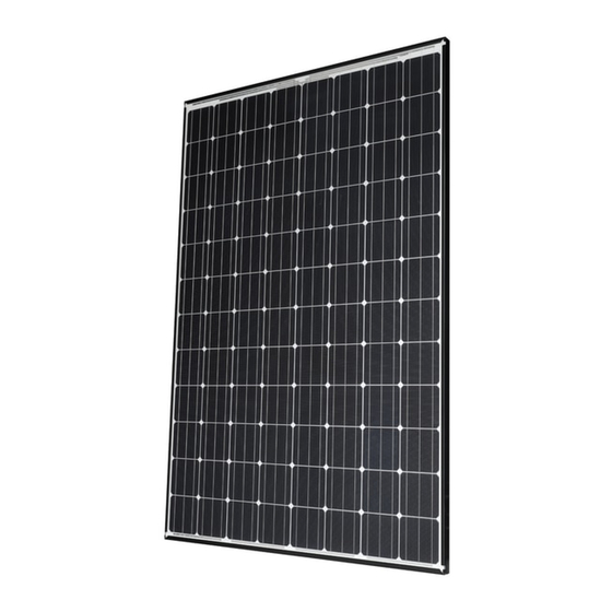
General Installation Manual
Photovoltaic Module HIT
AC MODULE
Model No. VBHN340SA17E, VBHN330SA17E
Model No. VBHN330KA03E, VBHN325KA03E
Microinverter IQ7X-96-ACM-US (Enphase Energy, Inc.)
Mounting on back of PV module
VBHNxxxSA17E
Thank you for choosing Panasonic photovoltaic module HIT
Please read this manual completely before you install or use
®
HIT
. With proper operation and maintenance, HIT
vide you with clean, renewable solar electricity for many years.
This manual contains important installation, maintenance and
safety information. The word "module" as used in this manual
refers to one or more PV modules. Retain this manual for
future reference.
"HIT" is a registered trademark of the Panasonic Group.
Enphase® is a registered trademark of Enphase Energy, Inc.
Other product and service names listed in this manual are trademarks or
registered trademarks of respective companies.
Specifications and information in this Installation Manual may change
without notice.
Check the latest version from the following website.
https://na.panasonic.com/us/energy-solutions/solar/ac-series-ac-module
®
VBHNxxxKA03E
®
.
®
will pro-
CONTENTS
AN ENPHASE Q AGGREGATOR
2
3
7
17
22
24
24
Advertisement
Table of Contents

Related Manuals for Panasonic HIT VBHN340SA17E


Summary of Contents for Panasonic HIT VBHN340SA17E
-
Page 1: Table Of Contents
DISCLAIMER OF LIABILITY future reference. CONTACT INFORMATION “HIT” is a registered trademark of the Panasonic Group. Enphase® is a registered trademark of Enphase Energy, Inc. Other product and service names listed in this manual are trademarks or registered trademarks of respective companies. -
Page 2: Safety Precautions
Do not damage the back sheet, ca- enough strength. installed by Panasonic. There are no ble and connector of a module. Do user serviceable parts within the Both roof construction and module not use the PV module if conductive module or junction box. -
Page 3: Module Specifications
“MODULE solar spectral irradiance per IEC ing instructions. INSTALLATION” 60904-3. Note: At the time of ship- ment, Panasonic guarantees the The models in this instructions are As UL Certified Load Ratings, this output level of its modules to be -0/... - Page 4 Table 1-1. Module Specification DC Electrical Specifications* Model VBHN340SA17E VBHN330SA17E VBHN330KA03E VBHN325KA03E Cell Number in Series Rated Power, Watts (Pmax) Maximum Power Voltage (Vpm) 59.7 58.0 59.5 59.2 Maximum Power Current (Ipm) 5.70 5.70 5.55 5.50 Open Circuit Voltage (Voc) 71.3 69.7 71.2...
- Page 5 Dimension in mm (150) or (215) ※ Section A-A Section B-B Side Backside Front Note) A module is installed using 4 points, symmetrical mounting within setting range (Black arrows). Setting range parameters are shown in “Mount Locations and Load Resistance” table. ※...
-
Page 6: Junction Box, Microinverter And Terminals
JUNCTION BOX, MICROINVERTER ing connector. Always use these connectors and do not detach them AND TERMINALS from cables. Modules equipped with one junc- The PV module and a microinverter tion box contain terminals for both come pre-wired. Each module has positive and negative polarity, and two #12 AWG type PV-wire stranded bypass diodes. -
Page 7: Bypass Diode
Conditions of Panasonic modules are to rain water and dust . BYPASS DIODE as follows: To avoid damage to the back sheet When the module is shaded partial- 1) The modules should be operated only by the connector, Do not cut the ly, it may cause reverse voltage in terrestrial applications. -
Page 8: Prepare The Microinverter
turns, and any obstructions. PREPARE THE MICROINVERTER If you need to service, you can return the microinverter to the shipping Mark the approximate centers of Before installing the PV module the position using theEnphase Discon- each PV module on the PV racking. microinverters must be lifted from nect Tool. -
Page 9: Connect The Microinverter
CONNECT THE MICROINVERTER Connect the Q Cable to the microin- verter. Listen for a click as the con- nectors engage. (See Figure 6) Q cable Cover any unused connectors with Enphase Sealing Caps. Listen for a click as the connectors engage. ... - Page 10 Figure 8. Installation Map (1)
- Page 11 Figure 9. Installation Map (2)
-
Page 12: Module Installation
300 Stainless steel, Stopper of electrolytic corrosion. Sleeves; 6000 Aluminum alloys Panasonic does not provide a war- Clearance between the roof surface ranty for clamps. The module war- Note: Please refer to IronRidge... - Page 13 270mm (10.6inch) (Refer to Page 5 Table 1-2) (150) or (215) ※ 250mm (5.9inch) or (8.5inch) Figure 11. Position of the mounting structure rail Note) Please fix the module so that the microinverter is not placed on the mounting structure rail. ※...
-
Page 14: Manage The Cabling
MANAGE THE CABLING Use cable clips to attach the cable to the PV module frame. Leave no more than 1.8 m (six feet) between cable clips. (See Figure 12) Dress any excess cabling in loops so that it does not come into contact with the roof. -
Page 15: Connect To A Junction Box Or
CONNECT TO A JUNCTION BOX OR AN ENPHASE Q AGGREGA- Connect the Enphase Q Cable into the Enphase Q Aggregator (See Figure 14).The Enphase Q Cable uses the following wiring color code. A ground lug is provided on the Q Aggregator for convenient PV module/rack/balance of system (BOS) grounding. - Page 16 Figure 15. Sample Wiring Diagram...
-
Page 17: Wiring
Please contact your Panasonic Au- codes for outdoor installation of thorized Representative with ques- wires in conduits. Minimum diame- tions regarding other electrical con- ter of wire conduit is 4 mm . -
Page 18: Earth Ground Wiring
EARTH GROUND WIRING GROUNDING METHODS Lay-in lugs or grounding clips can be used to ground Panasonic PV mod- A module with exposed conductive Where common grounding hard- ules. Both methods are explained parts is considered to be in compli- ware (nuts, bolts, star washers, spilt- below, please choose one. - Page 19 and the cup washer) so that the cup Using bolt and nut Using cup washers washer doesn’t contact the module (see Figures 16.2) (see Figures 16.2) frame and is fixed stably to the module frame. • The use of cup washers is to prevent If using this method, use one of the wire from slipping out from under the larger holes with diameter of...
- Page 20 10-14AWG-Solid -> 20 in-lbs, Using a lay-in lug with bolt and 4-6AWG-Strand -> 35 in-lbs, (see Figure 16-3.) 8AWG-Strand -> 25 in-lbs, 10- 14AWG-Strand -> 20 in-lbs If using this method, please follow instructions in previous section re- Burndy L L C CL501TN 14AWG- garding using bolts and nuts with Solid ->...
- Page 21 For more information, please refer to Using a Grounding Clip with bolt Instruction sheet issued by Tyco Electron- and nut (see Figure 16-4.) ics. Use Tyco Electronics 1954381-2 as grounding clip. Place the grounding clip onto the module frame. ...
-
Page 22: Maintenance
Install new replacement Microin- MAINTENANCE Never use abrasive detergent, verter to the deployed position. strong alkaline detergent, strong In order to maintain the optimum acid detergent or a detergent which Connect the DC connector to new output of the module, quality and forms a protective layer on the sur- Microinverter. - Page 23 Figure 17. Expanding the nails of the four corners.
-
Page 24: Disclaimer Of Liability
© SANYO Electric Co., Ltd. 2020 No license is granted by implication or under any patent or patent rights. The Petaluma, California SANYO is part of the Panasonic Group. information in this manual is believed to 1420 N. McDowell Blvd.Petaluma, CA IMA003-0820-5.1... - Page 25 REVISION HISTORY Edition Revision Date Revised Item Revised Content NEW Edition 2019.1.16 ・Request AC disconnector or breaker ・Request from UL and installation Enphase Edition 2019. 2. 8 ・Change Enphase registered trademark ・Correction of mistakes statement ・ Correction of missing sentences (p.8 ・Correction of missing sen- PREPARE THE MICROINVERTER~...