
Related Manuals for Notifier FCPS-24S6


Summary of Contents for Notifier FCPS-24S6
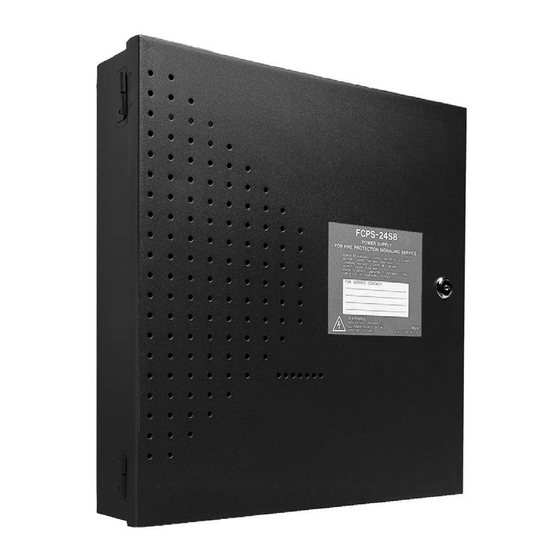
- Page 1 Field Charger/Power Supply FCPS-24S6 FCPS-24S8 Document #51977 8/06/03 Revision: PN: 51977:C1 ECN 03-396 www.PDF-Zoo.com...
- Page 2 Fire Alarm System Limitations While a fire alarm system may lower insurance rates, it is not a substitute for fire insurance! An automatic fire alarm system—typically made up of Heat detectors do not sense particles of combustion and smoke detectors, heat detectors, manual pull stations, audible alarm only when heat on their sensors increases at a predeter- warning devices, and a fire alarm control panel with remote mined rate or reaches a predetermined level.
- Page 3 Acclimate Plus™, AWACS™, HARSH™, NOTI•FIRE•NET™, ONYX™, and VeriFire™ are trademarks, and FlashScan®, UniNet®, and VIEW® are registered trademarks of NOTIFIER. NION™ is a trademark of NIS. NIS™ and Notifier Integrated Systems™ are trademarks and NOTIFIER® is a registered trademark of Fire•Lite Alarms, Inc. Echelon® is a registered trademark and LonWorks™ is a trademark of Echelon Corporation. ARCNET® is a registered trademark of Datapoint Corporation.
- Page 4 Notes FCPS-24S PN 51977:C1 08/06/03 www.PDF-Zoo.com...
-
Page 5: Table Of Contents
Table of Contents SECTION 1: System Overview ..........................7 1.1: General ................................7 1.2: Features ...............................7 1.3: Start-up Procedure............................8 1.4: Jumpers................................9 1.4.1: Jumper JP1 - Ground Fault Detection....................9 1.4.2: Jumpers JP2 and JP3: Coded/Noncoded Input Selection ......................9 1.5: LED Indicators ............................9 1.6: Specifications ..............................10 1.7: General ................................12 SECTION 2: Installation ............................13 2.1: Backbox Mounting ............................13... - Page 6 NEC Article 250 Grounding NEC Article 300 Wiring Methods NEC Article 760 Fire Protective Signaling Systems Applicable Local and State Building Codes Requirements of the Local Authority Having Jurisdiction (LAHJ) Other Notifier Documents: Device Compatibility Document Document #15378 FCPS-24S PN 51977:C1 08/06/03 www.PDF-Zoo.com...
-
Page 7: Section 1: System Overview
System Overview SECTION 1 The FCPS-24S6 is a 6 amp power supply and the FCPS-24S8 is an 8 amp power supply. Each FCPS-24S power supply is a compact, cost-effective, remote power supply and battery charger which provides ADA compatible strobe synchronization. The remote power supplies consist of a filtered 24 VDC output that can be configured to drive four Style Y (Class B) NACs (Notification Appliance Circuits). -
Page 8: Start-Up Procedure
System Overview Start-up Procedure • Maximum total short term current (one hour maximum): 6.0 amps for FCPS-24S6 8.0 amps for FCPS-24S8 • Integral supervised battery charger for lead acid batteries only • Capable of charging 7.0 AH to 18.0 AH (Amp Hour) batteries •... -
Page 9: Jumpers
Jumpers System Overview 1.4 Jumpers CAUTION! Remove all power (AC & DC) before cutting or moving any jumpers. 1.4.1 Jumper JP1 - Ground Fault Detection Jumper JP1 is located in the top right section of the power supply circuit board. Cutting JP1 will disable ground fault detection by the power supply. -
Page 10: Specifications
Style Z NACs using the optional ZNAC-4 Class A converter module Four resettable or nonresettable 24 VDC power outputs • Refer to Notifier Device Compatibility Document for listed compatible devices Trouble Relay Contact Rating - TB5 • Fail-safe Form-C relay (normally energized, transfers with loss of power) •... - Page 11 Specifications System Overview Power-limited, Supervised in NAC Mode with Jumpers JP5, JP6, JP7 & JP8 in positions shown below Nonpower-limited NAC/Out 1 + To Transformer #1 NAC/Out 1 - To Transformer #2 Trouble Relay NAC/Out 2 + Form-C Fail-safe NAC/Out 2 - Supervised (shown energized) NAC/Out 3 +...
-
Page 12: General
System Overview General 1.7 General The FCPS may be used in a number of different applications. It may be used as a remotely-mounted power supply and battery charger where it can provide up to four coded or noncoded, synchronized or nonsynchronized NACs (Notification Appliance Circuits). -
Page 13: Section 2: Installation
Backbox Mounting Installation Installation SECTION 2 Carefully unpack the system and check for shipping damage. Select a location for the cabinet that is in a clean, dry, vibration-free area where extreme temperatures are not encountered. The area should be readily accessible with sufficient room to easily install and maintain the power supply. - Page 14 Installation Backbox Mounting 2.875” (7.3 cm) Depth = 3.050” Backbox = 14.5” (7.75 cm) (36.8 cm) 0.75” (1.9 cm) 2.7” (6.86cm) 9.1” (23.1 cm) 10.625” (26.99 cm) Height=15.00” Mounting Plate Pem Studs (38.10 cm) Backbox Mounting Holes 1.125” (2.868 cm) Bottom Figure 2.2 Backbox Mounting Dimensions FCPS-24S...
-
Page 15: Nac Circuit Wiring
NAC Circuit Wiring Installation 2.2 NAC Circuit Wiring 2.2.1 Style Y (Class B) The standard configuration for NACs is Style Y (Class B) as shown in Figure 2.3. 4.7KΩ ELR Horn Strobe Alarm Polarity Shown Horn Strobe Horn Strobe 1 2 3 4 5 6 7 8 9 10 FCPS-24S Circuit Board Figure 2.3 NAC Style Y (Class B) 2.2.2 ZNAC-4 Class A Option Module... -
Page 16: Addressable Module Mounting
Installation Addressable Module Mounting 2.3 Addressable Module Mounting The FCPS-24S has been designed to allow the mounting of an addressable control, relay or monitor module on the main circuit board inside the power supply cabinet with the module status LED visible through the closed door. This allows power to be fed from the FCPS-24S Auxiliary Power output directly to the module, if needed, without running the power wires outside the cabinet. -
Page 17: Nec Power-Limited Wiring Requirements
NEC Power-limited Wiring Requirements Installation 2.4 NEC Power-limited Wiring Requirements Power-limited and nonpower-limited circuit wiring must remain separated in the cabinet. All power-limited circuit wiring must remain at least 0.25” away from any nonpower-limited circuit wiring. Furthermore, all power-limited circuit wiring and nonpower-limited circuit wiring must enter and exit the cabinet through different conduits. -
Page 18: Section 3: Programming Options
Programming Options NEC Power-limited Wiring Requirements Programming Options SECTION 3 This section describes the programming options available via DIP switch settings. The FCPS can be field programmed using option DIP switch SW1 which is located in the lower center of the circuit board. Refer to the following illustration for switch location and DIP switch placement in the ON and OFF positions. -
Page 19: Dip Switch Settings
DIP Switch Settings Programming Options 3.1 DIP Switch Settings The following table lists the FCPS programmable features and the switch settings required to select a particular feature. A detailed description of each feature is presented in the following pages. Table 3.1 DIP Switch Settings SW1 DIP Switch This switch works in conjunction with switch 2 to determine the Strobe Synchronization Type 1 OFF, 2 OFF = no sync (steady +24V) -
Page 20: Programmable Features Description
Programming Options Programmable Features Description 3.2 Programmable Features Description 3.2.1 Synchronization Type Selection Synchronization is a feature that controls the activation of notification appliances in such a way that all devices will turn on and off at exactly the same time. This is particularly critical when activating strobes which must be synchronized to avoid random activation and a potential hazard or confusion. -
Page 21: 4: Input/Output Function
Programmable Features Description Programming Options 3.2.4 Input/Output Function DIP switches 5 and 6 are used to determine the Input Control circuits that will activate the four output circuits and the function of the output circuits. For example, to configure a General Alarm operation in which Input Control Circuit #1 activates all four output NACs, DIP switches 5 and 6 are both set to the OFF position. -
Page 22: 5: Charger Enable/Disable
Programming Options Programmable Features Description 3.2.5 Charger Enable/Disable The FCPS-24S battery charger can be disabled to accommodate an external battery charger. Setting DIP switch 7 to the default setting of OFF will enable the battery charger. Setting DIP switch 7 to the ON position will disable the charger. It should only be disabled if an external battery charger is being used for the FCPS-24S. -
Page 23: Section 4: Trouble Supervision
Supervision via FACP Notification Appliance Circuit Trouble Supervision Trouble Supervision SECTION 4 4.1 Supervision via FACP Notification Appliance Circuit 4.1.1 Supervision of FACP to FCPS wiring The FACP (Fire Alarm Control Panel) supervises the connection between itself and the FCPS-24S via the control panels NAC End-of-Line Resistor (ELR). The ELR must be installed at the FCPS end of the circuit, after the last notification appliance on the circuit. -
Page 24: 3: Trouble Relay
Trouble Supervision AC Loss Reporting Delay 4.1.3 Trouble Relay The FCPS-24S power supply has one fail-safe Form-C trouble relay located at TB5. The contacts can be monitored by an FACP input circuit or an addressable monitor module. The following trouble conditions will cause the normally energized trouble relay to change states regardless of whether the panel is in alarm or standby: •... -
Page 25: Section 5: Applications
Controlling Four NACs With One Input and Selective Silence Applications Applications SECTION 5 5.1 Controlling Four NACs With One Input and Selective Silence In this application, the power supply has been set as a master with synchronized outputs and selective silence (see SW1 switch settings in following illustration). All four FCPS-24S output circuits, which are shown as NACs (Notification Appliance Circuits), can be controlled from one input such as an addressable control module as illustrated in Figure 5.1. - Page 26 Applications Controlling Four NACs With One Input and Selective Silence Notes: The following notes apply to Figure 5.1 on page 25. 1. When the FCPS-24S power supply is in an inactive state (control module not active), a trouble on the power supply will result in an open circuit condition on the control module output circuit (monitored by End-of-Line Resistor across TB4, Terminals 5 &...
-
Page 27: Controlling Three Nacs And One Door Holder With One Input
Controlling Three NACs and One Door Holder With One Input Applications 5.2 Controlling Three NACs and One Door Holder With One Input In this application, the power supply has been set as a master with synchronized outputs. All four FCPS-24S output circuits, three NACs and one door holder, can be controlled from one input such as an addressable control module as illustrated in Figure 5.2. - Page 28 Applications Controlling Three NACs and One Door Holder With One Input Notes: The following notes apply to Figure 5.2 on page 27. 1. The Output 4 door holder circuit will deactivate 60 seconds after Control Input #1 is activated or AC power is lost. 2.
-
Page 29: Split Temporal Mode Of Operation
Split Temporal Mode of Operation Applications 5.3 Split Temporal Mode of Operation In this application, the power supply has been set as a master with two synchronized and two nonsynchronized outputs as determined by the Split Temporal mode feature. Control Input #1 (TB4, Terminals 3 & 4) is connected to an addressable control module which will cause the synchronized power supply output circuits 1 &... - Page 30 Applications Split Temporal Mode of Operation Notes: The following notes apply to Figure 5.3 on page 29. 1. When the FCPS-24S power supply is in an inactive state (control module not active), a trouble on the power supply will result in an open circuit condition on the control module output circuit (monitored by End-of-Line Resistor across Terminals 5 &...
-
Page 31: Remote Supply With Resettable And Nonresettable Power
The FCPS-24S can be used as a remote stand-alone power supply to provide power to any devices that require filtered, resettable or nonresettable power. The FCPS-24S6 can provide up to 4 amps of continuous current and the FCPS-24S8 can provide up to 6 amps of continuous current. - Page 32 Applications Remote Supply With Resettable and Nonresettable Power Notes: The following notes apply to Figure 5.4 on page 31. 1. An End-of-Line Resistor must be installed between TB5, Terminal 1 (trouble relay common) and the monitor module input circuit for module wiring supervision (the ELR value is dependent on the module employed).
-
Page 33: Door Release Service For All Four Outputs
3. A monitor module may be used to monitor the FCPS-24S Trouble contacts at TB5. Any power supply trouble will cause the contacts to change states. 4. A maximum of 4.0 amps from the FCPS-24S6 and 6.0 amps from the FCPS-24S8 may be drawn continuously for holding doors 5. -
Page 34: Multiple Synchronized Fcps-24S Power Supplies
Applications Multiple Synchronized FCPS-24S Power Supplies 5.6 Multiple Synchronized FCPS-24S Power Supplies In this application, multiple FCPS-24S power supplies, configured as Slave units, are connected to a master FACP NAC programmed for synchronized output. Each power supply should be set for synchronization which matches the FACP programming. Note: FACP supplied selective silence function outputs will follow panel input. -
Page 35: Multiple Cascaded & Synchronized Fcps-24S Power Supplies
Multiple Cascaded & Synchronized FCPS-24S Power Supplies Applications 5.7 Multiple Cascaded & Synchronized FCPS-24S Power Supplies In this application, multiple FCPS-24S power supplies, configured as Slave units, are cascaded from a power supply which is connected to a master FACP NAC programmed for synchronized output. -
Page 36: Cascaded Fcps-24S Supplies From Nonsynchronized Source
Applications Cascaded FCPS-24S Supplies from Nonsynchronized Source 5.8 Cascaded FCPS-24S Supplies from Nonsynchronized Source In this application, multiple slave FCPS-24S power supplies are cascaded from a master power supply which is connected to an FACP NAC with nonsynchronized output. Each power supply should be set for synchronization which matches the master power supply. -
Page 37: Section 6: Power Supply Requirements
Overview Power Supply Requirements Power Supply Requirements SECTION 6 Overview This section contains instructions and tables for calculating power supply currents in alarm and standby conditions. This is a four-step process, consisting of the following: 1. Calculating the total amount of AC branch circuit current required to operate the system 2. -
Page 38: Calculating The System Current Draw
Use Table 6.3 on page 39 to calculate current draws as follows: 1. Enter the quantity of devices in all three columns 2. Enter the current draw where required. Refer to the Notifier Device Compatibility Document for compatible devices and their current draw 3. - Page 39 Calculating the System Current Draw Power Supply Requirements Table 6.3 contains three columns for calculating current draws. For each column, calculate the current and enter the total (in amperes) in the bottom row. When finished, copy the totals from Calculation Column 2 and Calculation Column 3 to Table 6.4 on page 40. Table 6.3 System Current Draw Calculations Device Type Calculate Column 1...
-
Page 40: Calculating The Battery Size
Power Supply Requirements Calculating the Battery Size 6.4 Calculating the Battery Size Use Table 6.4 to calculate the total Standby and Alarm load in ampere hours (AH). This total load determines the battery size (in AH) required to support the power supply under the loss of AC power. - Page 41 Index input circuit 7 control circuit 7 Loss 7 current 10 Loss Reporting Delay 24 see also input circuit 10 AC fail voltage 10 delay 20 current see also AC loss reporting delay 20 maximum continuous 7 AC loss maximum short term 8 reporting delay 20 standby 10 AC loss reporting...
- Page 42 Index battery/charger trouble 9 Charger Trouble 9 secondary power Ground Fault 9 see also battery 10 NAC Trouble 9 Specific Application Power LED indicators 9 see also Auxiliary Power 10 specifications 10 mounting Startup Procedure 8 see also installation 13 strobe synchronization 8 Style see also NFPA Style 7...
- Page 43 Limited Warranty NOTIFIER® warrants its products to be free from defects in materials and workmanship for eighteen (18) months from the date of manufacture, under normal use and service. Products are date stamped at time of manufacture. The sole and exclusive obligation of NOTIFIER® is to...
- Page 44 World Headquarters NOTIFIER is a company 12 Clintonville Road Northford, CT 06472-1653 USA 203-484-7161 fax 203-484-7118 www.notifier.com www.PDF-Zoo.com...
Need help?
Do you have a question about the FCPS-24S6 and is the answer not in the manual?
Questions and answers