
Related Manuals for NXP Semiconductors QorIQ LX2160A


Summary of Contents for NXP Semiconductors QorIQ LX2160A
- Page 1 NXP Semiconductors Document identifier: LX2160ARDBRM Reference Manual Rev. 4, 07/2020 QorIQ LX2160A Reference Design Board Reference Manual Supports LX2160ARDB Revision B...
- Page 2 NXP Semiconductors Contents Chapter 1 LX2160ARDB Overview................3 Chapter 2 LX2160ARDB Functional Description..........10 Chapter 3 Qixis Programming Model..............56 Appendix A Revision History................115 QorIQ LX2160A Reference Design Board Reference Manual, Rev. 4, 07/2020 Reference Manual 2 / 116...
-
Page 3: Chapter 1 Lx2160Ardb Overview
LX2160A reference design board (RDB) provides a comprehensive platform that enables design and evaluation of the QorIQ LX2160A processor. The LX2160ARDB comes preloaded with Layerscape software development kit (LSDK) image. The board comes in a 1U rackmount chassis form factor. It is lead-free and RoHS-compliant. - Page 4 SDRAM Synchronous dynamic random-access memory SerDes Serializer/deserializer SGMII Serial gigabit media independent interface Serial presence detect Serial peripheral interface Table continues on the next page... QorIQ LX2160A Reference Design Board Reference Manual, Rev. 4, 07/2020 Reference Manual 4 / 116...
- Page 5 LSDKUG.pdf Kit User Guide kit for NXP QorIQ Arm-based SoCs and the reference and evaluation boards available for them. Table continues on the next page... QorIQ LX2160A Reference Design Board Reference Manual, Rev. 4, 07/2020 Reference Manual 5 / 116...
- Page 6 Clocks 288 pins Up to 32 GB at 3200 MT/s SystemID Power supplies uATX USB_HVDD GVDD SD_SVDD OVDD 3.3V 5VSB Figure 1. LX2160ARDB block diagram QorIQ LX2160A Reference Design Board Reference Manual, Rev. 4, 07/2020 Reference Manual 6 / 116...
- Page 7 Table 3. LX2160ARDB features LX2160ARDB feature Specification Description Processor LX2160A processor QorIQ LX2160A processor, supporting speeds of up to 2.2 GHz. NOTE QorIQ For more details on the LX2160A processor, see LX2160A Reference Manual . DDR memory Two 72-bit DDR4...
- Page 8 • 12 V, 5 V, 3.3 V, and 5 V (standby) ATX power supplies • 0.8 V (VDD) for the LX2160A core Table continues on the next page... QorIQ LX2160A Reference Design Board Reference Manual, Rev. 4, 07/2020 Reference Manual 8 / 116...
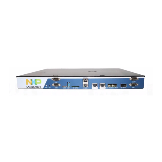
- Page 9 • General fault monitoring and logging 1.5 Board top view The figure below shows the top-side view of the LX2160ARDB. Figure 2. LX2160ARDB top view QorIQ LX2160A Reference Design Board Reference Manual, Rev. 4, 07/2020 Reference Manual 9 / 116...
-
Page 10: Chapter 2 Lx2160Ardb Functional Description
+5 V standby power. The ATX-compatible supply is managed by the system controller CPLD and drives the power supplies shown in the figures below. QorIQ LX2160A Reference Design Board Reference Manual, Rev. 4, 07/2020 Reference Manual 10 / 116... - Page 11 1.80V @ 5A PS_SD_OVDD_SEL MC34717EP/R2 SD_SVDD SD_VDD_FLT PS_SD_VDD_EN LX2160A SD_SVDD PS_SD_VDD_PG 0.92V @ 5A from CPLD SD3_VDD_FLT LX2160A SD3_SVDD Figure 3. Power supplies - Part 1 QorIQ LX2160A Reference Design Board Reference Manual, Rev. 4, 07/2020 Reference Manual 11 / 116...
- Page 12 Figure 4. Power supplies - Part 2 NOTE The LX2160A processor does not support EVDD operation at 3.3 V; however, the LX2160ARDB can enable it. QorIQ LX2160A Reference Design Board Reference Manual, Rev. 4, 07/2020 Reference Manual 12 / 116...
- Page 13 < 8.5 A at 100 Vac, 4 A at 240 Vac Power good Power-on delay time of 100 ~ 500 ms Operating temperature range 0 ~ 50 °C on full load Relative humidity 20~ 80% QorIQ LX2160A Reference Design Board Reference Manual, Rev. 4, 07/2020 Reference Manual 13 / 116...
- Page 14 (unmounted). NOTE Filtered OVDD power is also supplied to the core CPU PLLs (AVDD[1:5] and AVDD_D[1:2]). Table continues on the next page... QorIQ LX2160A Reference Design Board Reference Manual, Rev. 4, 07/2020 Reference Manual 14 / 116...
- Page 15 NX5P2924BUK USB_HVDD_ 3.3 V at 1 A Supplies power to the 3.3 Semiconductors V USB PHY HS power supply Table continues on the next page... QorIQ LX2160A Reference Design Board Reference Manual, Rev. 4, 07/2020 Reference Manual 15 / 116...
- Page 16 This voltage is used to generate the 3V3_SB and 1V8_SB standby power supplies, which are used to power the CPLD. QorIQ LX2160A Reference Design Board Reference Manual, Rev. 4, 07/2020 Reference Manual 16 / 116...
- Page 17 The LX2160ARDB implements onboard current and power measurements only for the VDD supply. For selected other supplies, monitoring resistors are available. The table below lists all measurable supplies. QorIQ LX2160A Reference Design Board Reference Manual, Rev. 4, 07/2020 Reference Manual...
- Page 18 All the clocks are fixed frequency, and most are produced by the Si5341B or Si52208. The following table summarizes the specifications of each clock and the component that provides it. QorIQ LX2160A Reference Design Board Reference Manual, Rev. 4, 07/2020 Reference Manual...
- Page 19 1.8 V OUT7: EC_CLK125 / Ethernet controller / • Frequency: 125 CLK_1588_CGEN IEEE 1588 port • Output type: LVCMOS Table continues on the next page... QorIQ LX2160A Reference Design Board Reference Manual, Rev. 4, 07/2020 Reference Manual 19 / 116...
- Page 20 2.3 DDR interface The LX2160ARDB supports two high-speed DDR4 memory ports: DDR#1 and DDR#2. The figure below shows the architecture of the DDR#1 memory port. QorIQ LX2160A Reference Design Board Reference Manual, Rev. 4, 07/2020 Reference Manual 20 / 116...
- Page 21 (2.5 V I/O shifted) 0x51 0x52 I2C1_CH0_2V5 DDR4 UDIMM 288-pin sockets Figure 9. DDR#1 memory port architecture The figure below shows the architecture of the DDR#2 memory port. QorIQ LX2160A Reference Design Board Reference Manual, Rev. 4, 07/2020 Reference Manual 21 / 116...
- Page 22 • Supports only DDR4 memory • Supports 4-bit memory devices with minor board modification to remove pull-down resistors that are mounted on the D1 or D2 MDQS[9:17]_N traces QorIQ LX2160A Reference Design Board Reference Manual, Rev. 4, 07/2020 Reference Manual 22 / 116...
- Page 23 The LX2160A processor supports three SerDes modules (SerDes1, SerDes2, and SerDes3), each having eight high-speed serial communication lanes. Each SerDes lane supports speeds of up to 25 GHz. The figure below shows the LX2160ARDB SerDes architecture. QorIQ LX2160A Reference Design Board Reference Manual, Rev. 4, 07/2020 Reference Manual 23 / 116...
- Page 24 SerDes 3 : x8 : BackSide Lanes Protocol PCIe.5 x8 Clocks 100.00 MHz Figure 12. SerDes protocol combinations The table below shows the LX2160ARDB SerDes assignments. QorIQ LX2160A Reference Design Board Reference Manual, Rev. 4, 07/2020 Reference Manual 24 / 116...
- Page 25 The two RJ45 jacks are stacked on the board such that jack for EC1 is at the bottom and jack for EC2 is at the top. The figure below shows the architecture of the Ethernet controller interface. QorIQ LX2160A Reference Design Board Reference Manual, Rev. 4, 07/2020 Reference Manual 25 / 116...
- Page 26 Ethernet controllers to time-stamp the incoming packets. A 12-pin header is provided on the board to allow access to the IEEE 1588 system (see figure below). QorIQ LX2160A Reference Design Board Reference Manual, Rev. 4, 07/2020 Reference Manual 26 / 116...
- Page 27 2.6 Ethernet management interface The LX2160ARDB has two Ethernet management interfaces, EMI1 and EMI2, for controlling PHY transceivers. The figure below shows the PHY device connections. QorIQ LX2160A Reference Design Board Reference Manual, Rev. 4, 07/2020 Reference Manual 27 / 116...
- Page 28 I2C2 must be programmed in the RCW to serve as the card detect (CD_B) and write protect (WP) pins for eSDHC1 interface. This happens automatically when the SD card slot is selected as the boot device. The figure below shows the eSDHC1 connections in the LX2160ARDB. QorIQ LX2160A Reference Design Board Reference Manual, Rev. 4, 07/2020 Reference Manual 28 / 116...
- Page 29 Manufacturer Memory size Notes MTFC128GAJAECE-IT Micron 128 GB Supported by default SDINADF4-128G Sandisk 128 GB The figure below shows the eSDHC2 connections in the LX2160ARDB. QorIQ LX2160A Reference Design Board Reference Manual, Rev. 4, 07/2020 Reference Manual 29 / 116...
- Page 30 Samtec VB_XSPI_EMU_B TFM-110-02-S-D-SN-K-TR 0.05" 2x10 “ISP-B” XSPI_A_D[0:7] XSPI_A_DQS XSPI_A_SCK Figure 18. XSPI architecture The table below shows the devices attached to the LX2160ARDB XSPI interface. QorIQ LX2160A Reference Design Board Reference Manual, Rev. 4, 07/2020 Reference Manual 30 / 116...
- Page 31 The LX2160ARDB supports two universal serial bus (USB) 3.0 controllers, with each port connected to a different type of USB connector for maximum flexibility. The table below describes the USB ports. QorIQ LX2160A Reference Design Board Reference Manual, Rev. 4, 07/2020 Reference Manual...
- Page 32 Board Errata . Each USB connector has an LED nearby, USB1_5V and USB2_5V, which are active when the +5 V USB power supply is enabled. QorIQ LX2160A Reference Design Board Reference Manual, Rev. 4, 07/2020 Reference Manual 32 / 116...
- Page 33 "I2C1_CH0" as it is named. Channel 0 is the default selection upon reset so that software has immediate access to critical resources. The I2C devices indirectly available on the I2C1 bus are shown in the figure below. QorIQ LX2160A Reference Design Board Reference Manual, Rev. 4, 07/2020 Reference Manual 33 / 116...
- Page 34 Provides I2C booting option 0x51 256-byte EEPROM SPD data Stores SPD and temperature data for DDR#1 UDIMM connector 1 Table continues on the next page... QorIQ LX2160A Reference Design Board Reference Manual, Rev. 4, 07/2020 Reference Manual 34 / 116...
- Page 35 Memory for booting 40 GbE CS4223 I2C1_CH7 0x75 NXP PCA9547PW I2C bus multiplexer Converts I2C1_CH7 (secondary) channel into eight sub- channels Table continues on the next page... QorIQ LX2160A Reference Design Board Reference Manual, Rev. 4, 07/2020 Reference Manual 35 / 116...
- Page 36 On the LX2160ARDB, the UART ports are available for external connection through a dual-port stacked DB9 male connector. Two RS-232 transceivers (Linear Technology LTC2804-1) translate the signals to RS-232 levels. The figure below shows the UART architecture. QorIQ LX2160A Reference Design Board Reference Manual, Rev. 4, 07/2020 Reference Manual 36 / 116...
- Page 37 UART3_SOUT/UART4_SOUT. To evaluate UART3 and/or UART4, a custom DB9 interface cable must be created, as shown in the following figure. Figure 23. 4-wire to 2-wire UART adapter QorIQ LX2160A Reference Design Board Reference Manual, Rev. 4, 07/2020 Reference Manual 37 / 116...
- Page 38 GPIO use. The interrupts are connected as shown in the figure below. QorIQ LX2160A Reference Design Board Reference Manual, Rev. 4, 07/2020 Reference Manual...
- Page 39 IRQ pins IRQ[0:11] and EVT pins EVT[0:4] but only when those pins are not used for IRQ or other purposes. The following figure shows the GPIO access header. QorIQ LX2160A Reference Design Board Reference Manual, Rev. 4, 07/2020 Reference Manual...
- Page 40 PHY_25G_LOL (if SFP2_MOD_ABS is low) IRQ10 GPIO3[10] PHY_25G_LOL (if SFP3_MOD_ABS is low) IRQ11 GPIO3[11] IRQ_QSFP_B EVT0_B GPIO3[12] EVT1_B GPIO3[13] Table continues on the next page... QorIQ LX2160A Reference Design Board Reference Manual, Rev. 4, 07/2020 Reference Manual 40 / 116...
- Page 41 Thermal monitoring happens with no programming involved. However, if the thermal limit, by default set as 85 °C, is higher than desired, it will need to be re-programmed. To change the thermal trip point, issue the I2C writes listed in the table below. QorIQ LX2160A Reference Design Board Reference Manual, Rev. 4, 07/2020 Reference Manual 41 / 116...
- Page 42 SW_XMAP[2:0]: Controls how XSPI_A chip-selects are connected to devices/peripherals. CFG_XSPI_MAP[3:0] Bit value XSPI_A_CS0 XSPI_A_CS1 Description 000 (default DEV#0 DEV#1 Boot from default setting) flash memory QorIQ LX2160A Reference Design Board Reference Manual, Rev. 4, 07/2020 Reference Manual 42 / 116...
- Page 43 SW_DDRSRC / SW_ENGUSE2 CFG_ENG_USE2 • 0: DDR clocked from DDRCLK pin (default setting) • 1: DDR clocked from differential SYSCLK Table continues on the next page... QorIQ LX2160A Reference Design Board Reference Manual, Rev. 4, 07/2020 Reference Manual 43 / 116...
- Page 44 SW_BOOTBOX_B • 0: Enable Boot Box mode • 1: Normal operating mode (default setting) VDD power enable SW4[6] SW_VDD_DIS Table continues on the next page... QorIQ LX2160A Reference Design Board Reference Manual, Rev. 4, 07/2020 Reference Manual 44 / 116...
- Page 45 • One or more power supplies have not started • Software has set the register CTL[0] (FAIL) to indicate a software fault Table continues on the next page... QorIQ LX2160A Reference Design Board Reference Manual, Rev. 4, 07/2020 Reference Manual 45 / 116...
- Page 46 0V85 power supply is operating correctly Green VTT1 VTT1 power supply is operating correctly Green SD_VDD power supply is operating correctly Table continues on the next page... QorIQ LX2160A Reference Design Board Reference Manual, Rev. 4, 07/2020 Reference Manual 46 / 116...
- Page 47 Tier 1 => 0V85, 0V9, 1V2 0000 0010 0011 0000 Tier 2 => VDD, OVDD, 2V1, 2V5, SD_AVDD, 0000 0011 USB_SVDD Table continues on the next page... QorIQ LX2160A Reference Design Board Reference Manual, Rev. 4, 07/2020 Reference Manual 47 / 116...
- Page 48 LED: M[3:0] Description IDLE 0000 = 0x0 Waiting for initial reset events RECONFIG 0010 = 0x2 Update configuration from registers Table continues on the next page... QorIQ LX2160A Reference Design Board Reference Manual, Rev. 4, 07/2020 Reference Manual 48 / 116...
- Page 49 • System alert monitoring and status display • Remapping of system boot devices • Handling of board control and status registers The following two figures show the system controller architectural details. QorIQ LX2160A Reference Design Board Reference Manual, Rev. 4, 07/2020 Reference Manual 49 / 116...
- Page 50 25 MHz PCB_REV[2:0] 000 = “Rev A” 3.3V LVCMOS 001 = “Rev B” Selectively DNP resistors to encode PCB rev Figure 29. System controller architecture QorIQ LX2160A Reference Design Board Reference Manual, Rev. 4, 07/2020 Reference Manual 50 / 116...
- Page 51 PORESET_B, such as RCW_SRC in DUTCFG0. Changes to DUTCFG registers only take effect on the next reset or reconfiguration event. The following figure shows the configuration hardware arrangement. QorIQ LX2160A Reference Design Board Reference Manual, Rev. 4, 07/2020 Reference Manual...
- Page 52 1. TEST_SEL_B is a static signal (constantly driven), unlike most other processor configuration signals. All other configuration signals are static and unrelated to the processor. The following table summarizes these configuration signals. QorIQ LX2160A Reference Design Board Reference Manual, Rev. 4, 07/2020 Reference Manual 52 / 116...
- Page 53 Enable group 2 power supplies, wait for all members to supplies. report “power good” (if supported): • VDD • SD_SVDD Table continues on the next page... QorIQ LX2160A Reference Design Board Reference Manual, Rev. 4, 07/2020 Reference Manual 53 / 116...
- Page 54 Registers that default to switch values are set now. Drive configuration values. Reset-sampled configuration signals are driven: • CFG_RCW_SRC[3:0] Table continues on the next page... QorIQ LX2160A Reference Design Board Reference Manual, Rev. 4, 07/2020 Reference Manual 54 / 116...
- Page 55 The CPLD has finished reset management. The reset sequencer watches for reset switch events and will restart at reset sequencer step 1 if any are detected. QorIQ LX2160A Reference Design Board Reference Manual, Rev. 4, 07/2020 Reference Manual 55 / 116...
-
Page 56: Chapter 3 Qixis Programming Model
SFP CSR 2 (SFP2) 10110000b 019h SFP CSR 3 (SFP3) 10110000b 01Ah LOS Status (LOS) 00000000b 01Dh Watchdog (WATCH) 00011111b 01Fh Table continues on the next page... QorIQ LX2160A Reference Design Board Reference Manual, Rev. 4, 07/2020 Reference Manual 56 / 116... - Page 57 060h DUT Configuration 1 (DUTCFG1) 11111111b 061h DUT Configuration 2 (DUTCFG2) 11111xxxb 062h DUT Configuration 6 (DUTCFG6) 1111111xb 066h Table continues on the next page... QorIQ LX2160A Reference Design Board Reference Manual, Rev. 4, 07/2020 Reference Manual 57 / 116...
- Page 58 Read as 0. Write zeroes to unused bits. Future definitions of reserved bits will maintain backward compatibility with the above rules. 3.2 Resets The reset values for registers are defined as follows: QorIQ LX2160A Reference Design Board Reference Manual, Rev. 4, 07/2020 Reference Manual 58 / 116...
- Page 59 The ID register contains a unique classification number. This ID number is used by system software to identify board types. The ID number remains same for all board revisions. Diagram Bits NONE Fields Field Function The board-specific identifier for the system. 42h= LX2160ARDB QorIQ LX2160A Reference Design Board Reference Manual, Rev. 4, 07/2020 Reference Manual 59 / 116...
- Page 60 Software may use this field to print board version identification, such as: char brd_ver = (get_pixis( VER ) & 0Fh); printf("Board Version: %c", brd_ver + 'A' - 1 ); QorIQ LX2160A Reference Design Board Reference Manual, Rev. 4, 07/2020 Reference Manual 60 / 116...
- Page 61 3.7 Programming Model (MODEL) Address Register Offset MODEL 003h Function The MODEL register contains information about the software programming model version and PCB Bill Of Materials (BOM) information. QorIQ LX2160A Reference Design Board Reference Manual, Rev. 4, 07/2020 Reference Manual 61 / 116...
- Page 62 Qixis QTAG facility but more than the limited MINOR facility on other RDBs. Writes to MINOR select various pieces of information for subsequent read. On reset, the 'minor revision' field is returned, for backward-compatibility. QorIQ LX2160A Reference Design Board Reference Manual, Rev. 4, 07/2020 Reference Manual 62 / 116...
- Page 63 This block of registers control the operation of Qixis itself (or other operations which do not constitute controlling the board or the DUT, which are managed with BRDCFG/DUTCFG registers) or monitor the status of various things. QorIQ LX2160A Reference Design Board Reference Manual, Rev. 4, 07/2020 Reference Manual...
- Page 64 0= Diagnostic LEDs operate normally. 1= Software can directly control the M7:M0 monitoring LEDs using the LED register. Software Failure Diagnostic LED: Table continues on the next page... QorIQ LX2160A Reference Design Board Reference Manual, Rev. 4, 07/2020 Reference Manual 64 / 116...
- Page 65 Bits ARST 00000000 Fields Field Function User-defined value. 3.12 System Status (STAT_SYS) Address Register Offset STAT_SYS 009h Function The STAT_SYS register reports general system status. QorIQ LX2160A Reference Design Board Reference Manual, Rev. 4, 07/2020 Reference Manual 65 / 116...
- Page 66 The ALARM register detects and reports any alarms raised in the QIXIS system. Write 1 to an ALARM register bit to prevent Qixis from recognizing that alarm condition. By default, all alarms are handled. QorIQ LX2160A Reference Design Board Reference Manual, Rev. 4, 07/2020 Reference Manual...
- Page 67 Temperature Alert: TALERT 0= The temperature is within normal limits. 1= The temperature has exceeded fault limits. Table continues on the next page... QorIQ LX2160A Reference Design Board Reference Manual, Rev. 4, 07/2020 Reference Manual 67 / 116...
- Page 68 3.15 Presence Detect 2 (STAT_PRES2) Address Register Offset STAT_PRES2 00Ch Function The STAT_PRES2 register detects the installation of cards in various PCI Express or SGMII slots. QorIQ LX2160A Reference Design Board Reference Manual, Rev. 4, 07/2020 Reference Manual 68 / 116...
- Page 69 LEDs is possible only when CTL[LED] is set to 1; otherwise they are used to display general system activity. Diagram Bits GRST 00000000 Fields Field Function LED Status Control: 0= LED M[bitno] is off. 1= LED M[bitno] is on. QorIQ LX2160A Reference Design Board Reference Manual, Rev. 4, 07/2020 Reference Manual 69 / 116...
- Page 70 NOTE: This is not a highly-secure watchdog; software can reset this bit at any time and disable the watchdog. Reserved. Table continues on the next page... QorIQ LX2160A Reference Design Board Reference Manual, Rev. 4, 07/2020 Reference Manual 70 / 116...
- Page 71 1= No QSFP module is detected. Reserved. Reserved. QSFP_LPMODE Control: LPMODE 0= QSFP module is in normal power mode. Table continues on the next page... QorIQ LX2160A Reference Design Board Reference Manual, Rev. 4, 07/2020 Reference Manual 71 / 116...
- Page 72 Reserved. SFP2_TX_FAULT Status: TXFLT 0= SFP module reports no transmit errors. 1= SFP module reports transmit fault. SFP2_RX_LOS Status: Table continues on the next page... QorIQ LX2160A Reference Design Board Reference Manual, Rev. 4, 07/2020 Reference Manual 72 / 116...
- Page 73 0= An SFP module is installed in the SFP cage. 1= No SFP module is detected. Reserved. SFP3_TX_FAULT Status: Table continues on the next page... QorIQ LX2160A Reference Design Board Reference Manual, Rev. 4, 07/2020 Reference Manual 73 / 116...
- Page 74 The LOS register reports LOS (Loss Of Signal) or LOL (Loss of Lock) for various interfaces. Diagram Bits CKLOL RT25G NONE 000000 Fields Field Function Reserved. SI5341 Loss of Lock: Table continues on the next page... QorIQ LX2160A Reference Design Board Reference Manual, Rev. 4, 07/2020 Reference Manual 74 / 116...
- Page 75 Watchdog timer value, as determined by the formula: WATCH time-out = ( WATCH * 2 ) + 2 sec Table continues on the next page... QorIQ LX2160A Reference Design Board Reference Manual, Rev. 4, 07/2020 Reference Manual 75 / 116...
- Page 76 1= On the 0-to-1 transition, toggle the system power supply. The bit must be reset to zero before additional power cycles can occur. Qixis interfaces which are powered from system power (as opposed to standby power) cannot power-up the system. Reserved. QorIQ LX2160A Reference Design Board Reference Manual, Rev. 4, 07/2020 Reference Manual 76 / 116...
- Page 77 0111= PWR_SW switch used to power off. 1010= Thermal fault forced power off. 1111= Unknown 3.27 Power Status 0 (PWR_MSTAT) Address Register Offset PWR_MSTAT 024h QorIQ LX2160A Reference Design Board Reference Manual, Rev. 4, 07/2020 Reference Manual 77 / 116...
- Page 78 Reports the current power savings level, for those devices which support it. SSTATE 11= S3 - completely on Note: If a device does not support hardware (i.e external) power savings modes, S3 is always reported. QorIQ LX2160A Reference Design Board Reference Manual, Rev. 4, 07/2020 Reference Manual 78 / 116...
- Page 79 SD_AVDD 0= Power supply is disabled or faulted. 1= Power supply is operating. SD_SVDD and SD_OVDD Power Supply Status: Table continues on the next page... QorIQ LX2160A Reference Design Board Reference Manual, Rev. 4, 07/2020 Reference Manual 79 / 116...
- Page 80 Field Function TA_BB Power Supply Status: TA_BB 0= Power supply is disabled or faulted. 1= Power supply is operating. Table continues on the next page... QorIQ LX2160A Reference Design Board Reference Manual, Rev. 4, 07/2020 Reference Manual 80 / 116...
- Page 81 Values in the CLK_SPD1 register are used by boot software accurately initialize timing-dependent parameters, such as for UART baud rates, I2C clock rates, and DDR memory timing. QorIQ LX2160A Reference Design Board Reference Manual, Rev. 4, 07/2020 Reference Manual 81 / 116...
- Page 82 The CLK_ID register is used to identify the arrangement of the clock control registers. Software should check CLK_ID register before attempting to interpret/control the clock control registers. Diagram Bits NONE 0000 0000 Fields Field Function Reserved. Table continues on the next page... QorIQ LX2160A Reference Design Board Reference Manual, Rev. 4, 07/2020 Reference Manual 82 / 116...
- Page 83 SW1[5] selects between disabled mode (00) and normal mode (11), other modes can only be set via software. Note: Software cannot change this field if SW1[5] is 0. Table continues on the next page... QorIQ LX2160A Reference Design Board Reference Manual, Rev. 4, 07/2020 Reference Manual 83 / 116...
- Page 84 1= Reset sequencer is in RMT-WAIT state, waiting for permission to proceed. System Reset: SYSRST 0= System is operating normally. 1= System is in reset. Reserved. HRESET_B status: Table continues on the next page... QorIQ LX2160A Reference Design Board Reference Manual, Rev. 4, 07/2020 Reference Manual 84 / 116...
- Page 85 Previous reset reason: PREV (see REASON field codes) Reset Reason: REASON 0000= Power-on reset 0001= JTAG_RST_B asserted 0010= (reserved) Table continues on the next page... QorIQ LX2160A Reference Design Board Reference Manual, Rev. 4, 07/2020 Reference Manual 85 / 116...
- Page 86 GRST Fields Field Function 1= Assert RST_CLKGEN_B. 1= Assert RST_XSPI_B. XSPI 1= Assert RST_QSFP_B. QSFP 1= Assert RST_I2CMUX_B. I2CMUX Table continues on the next page... QorIQ LX2160A Reference Design Board Reference Manual, Rev. 4, 07/2020 Reference Manual 86 / 116...
- Page 87 1= Assert RST_PHY_10G_B to the Aquantia AQR107 10Gbps PHY. PHY10 1= Assert RST_PHY_25G_B to the 25Gbps retimer. PHY25 1= Assert RST_PHY_40G_B to the CS4223 40GE PHY. Table continues on the next page... QorIQ LX2160A Reference Design Board Reference Manual, Rev. 4, 07/2020 Reference Manual 87 / 116...
- Page 88 Diagram Bits SLOT1 SLOT2 IEEE GRST 00000 Fields Field Function 1= Assert RST_SLOT1_B. SLOT1 1= Assert RST_SLOT2_B. SLOT2 Reserved. Table continues on the next page... QorIQ LX2160A Reference Design Board Reference Manual, Rev. 4, 07/2020 Reference Manual 88 / 116...
- Page 89 ARST Fields Field Function 1= Mask RST_CLKGEN_B. 1= Mask RST_XSPI_B. XSPI 1= Mask RST_QSFP_B. QSFP 1= Mask RST_I2CMUX_B. I2CMUX Table continues on the next page... QorIQ LX2160A Reference Design Board Reference Manual, Rev. 4, 07/2020 Reference Manual 89 / 116...
- Page 90 1= Mask RST_PHY_10G_B to the Aquantia AQR107 10Gbps PHY. PHY10 1= Mask RST_PHY_25G_B to the 25Gbps retimer. PHY25 1= Mask RST_PHY_40G_B to the CS4223 40GE PHY. Table continues on the next page... QorIQ LX2160A Reference Design Board Reference Manual, Rev. 4, 07/2020 Reference Manual 90 / 116...
- Page 91 Diagram Bits SLOT1 SLOT2 IEEE ARST 00000 Fields Field Function 1= Mask RST_SLOT1_B. SLOT1 1= Mask RST_SLOT2_B. SLOT2 Reserved. Table continues on the next page... QorIQ LX2160A Reference Design Board Reference Manual, Rev. 4, 07/2020 Reference Manual 91 / 116...
- Page 92 • Boot from a known-good image. • Boot from an alternate (test) image before committing as a known-good image. • Boot from an emulator to program blank flash. QorIQ LX2160A Reference Design Board Reference Manual, Rev. 4, 07/2020 Reference Manual 92 / 116...
- Page 93 051h Function The BRDCFG1 register shows/controls SYSCLK and DDRCLK speeds. Diagram Bits DDRCLK SYSCLK RRST Fields Field Function Reserved. Table continues on the next page... QorIQ LX2160A Reference Design Board Reference Manual, Rev. 4, 07/2020 Reference Manual 93 / 116...
- Page 94 Bits SD1CK1 SD1CK2 SD2CK1 SD2CK2 RRST Fields Field Function SerDes1 Clock #1 (F) Rate: SD1CK1 11= 161.1328125 MHz (fixed) Table continues on the next page... QorIQ LX2160A Reference Design Board Reference Manual, Rev. 4, 07/2020 Reference Manual 94 / 116...
- Page 95 SerDes3 Clock #1 (F) Rate: SD3CK1 00= 100.0000000 MHz (fixed) SerDes3 Clock #2 (S) Rate: SD3CK2 00= 100.0000000 MHz (fixed) Table continues on the next page... QorIQ LX2160A Reference Design Board Reference Manual, Rev. 4, 07/2020 Reference Manual 95 / 116...
- Page 96 0= CS4223 40GE PHY should power up unconfigured. 1= CS4223 40GE PHY should use its configuration EEPROM for initial settings and DSP software load. Table continues on the next page... QorIQ LX2160A Reference Design Board Reference Manual, Rev. 4, 07/2020 Reference Manual 96 / 116...
- Page 97 3.50 DUT Configuration 0 (DUTCFG0) Address Register Offset DUTCFG0 060h Function The DUTCFG0 register is used to select the boot device used upon reset (cfg_rcw_src). QorIQ LX2160A Reference Design Board Reference Manual, Rev. 4, 07/2020 Reference Manual 97 / 116...
- Page 98 061h Function The DUTCFG1 register holds the LSB of cfg_rcw_src values when they are larger than 8 bits. For the LX2160ARDB, this register is ignored. QorIQ LX2160A Reference Design Board Reference Manual, Rev. 4, 07/2020 Reference Manual 98 / 116...
- Page 99 XX= Selected processor variant (refer to the device Reference Manual). NOTE: SVR settings must match installed device. Controls Test Select (config TEST_SEL_B): Table continues on the next page... QorIQ LX2160A Reference Design Board Reference Manual, Rev. 4, 07/2020 Reference Manual 99 / 116...
- Page 100 The DUTCFG6 register is used to sample device-specific test modes. Diagram Bits RRST 111111 SW3[4] Fields Field Function Reserved. Reserved. Controls cfg_soc_use. 1= Default. 3.54 DUT Configuration 11 (DUTCFG11) Address Register Offset DUTCFG11 06Bh QorIQ LX2160A Reference Design Board Reference Manual, Rev. 4, 07/2020 Reference Manual 100 / 116...
- Page 101 The DUTCFG12 register is used to provide the general-purpose GPCFG signals. These settings are sampled by the processor for customers to use as desired, but have no hardware effects. QorIQ LX2160A Reference Design Board Reference Manual, Rev. 4, 07/2020 Reference Manual...
- Page 102 Fan interrupt (from EMC2305) IRQ9 IN112525 PHY LOL if SFP2 MOD_ABS low IRQ10 IN112525 PHY LOL if SFP3 MOD_ABS low IRQ11 zQSFP+ transceiver (40G PHY) interrupt TMPDETB TMP_DETECT_B QorIQ LX2160A Reference Design Board Reference Manual, Rev. 4, 07/2020 Reference Manual 102 / 116...
- Page 103 1= IRQ1_B signal is high. IRQ1 Reserved. 1= IRQ6_B signal is high. IRQ6 1= IRQ7_B signal is high. IRQ7 3.58 Interrupt Status 1 (IRQSTAT1) Address Register Offset IRQSTAT1 091h QorIQ LX2160A Reference Design Board Reference Manual, Rev. 4, 07/2020 Reference Manual 103 / 116...
- Page 104 3.59 Interrupt Control 0 (IRQCTL0) Address Register Offset IRQCTL0 094h Function The IRQCTL0 register allows defining interrupt output modes for IRQ[0:3], where relevant to the target system. QorIQ LX2160A Reference Design Board Reference Manual, Rev. 4, 07/2020 Reference Manual 104 / 116...
- Page 105 3.60 Interrupt Control 2 (IRQCTL2) Address Register Offset IRQCTL2 096h Function The IRQCTL2 register allows defining interrupt output modes for IRQ[8:11], where relevant to the target system. QorIQ LX2160A Reference Design Board Reference Manual, Rev. 4, 07/2020 Reference Manual 105 / 116...
- Page 106 IRQ10 (same as IRQ9). Reserved. 3.61 Interrupt Drive 0 (IRQDRV0) Address Register Offset IRQDRV0 098h Function The IRQDRV0 register allows control of selected interrupt pins. QorIQ LX2160A Reference Design Board Reference Manual, Rev. 4, 07/2020 Reference Manual 106 / 116...
- Page 107 The status of IRQ1_B can be monitored with the IRQSTAT registers. Reserved. 3.62 Interrupt Drive 1 (IRQDRV1) Address Register Offset IRQDRV1 099h Function The IRQDRV1 register allows control of selected interrupt pins. QorIQ LX2160A Reference Design Board Reference Manual, Rev. 4, 07/2020 Reference Manual 107 / 116...
- Page 108 The status of IRQ7_B can be monitored with the IRQSTAT registers. 3.63 Interrupt Drive 2 (IRQDRV2) Address Register Offset IRQDRV2 09Ah Function The IRQDRV2 register allows control of selected interrupt pins. QorIQ LX2160A Reference Design Board Reference Manual, Rev. 4, 07/2020 Reference Manual 108 / 116...
- Page 109 The status of IRQ11_B can be monitored with the IRQSTAT registers. 3.64 Interrupt Drive 5 (IRQDRV5) Address Register Offset IRQDRV5 09Dh Function The IRQDRV5 register allows control of selected interrupt pins. QorIQ LX2160A Reference Design Board Reference Manual, Rev. 4, 07/2020 Reference Manual 109 / 116...
- Page 110 = Qixis_Get_Reg( CMS_D ); for (i = 1; i <= nr; i++) { Qixis_Set_Reg( CMS_A, i ); printf("SW%1d = %02X\\ n", i, Qixis_Get_Reg( CMS_D )); QorIQ LX2160A Reference Design Board Reference Manual, Rev. 4, 07/2020 Reference Manual 110 / 116...
- Page 111 3.67 Core Management Data (CMSD) Address Register Offset CMSD 0D9h Function CMSD contains the value of a CMS register selected by CMSA. See CMSA for details. QorIQ LX2160A Reference Design Board Reference Manual, Rev. 4, 07/2020 Reference Manual 111 / 116...
- Page 112 SWS_CTL 0DCh Function The SWS_CTL register manages the switch sampler. Diagram Bits POLL ARST 0000 Fields Field Function Reserved. Table continues on the next page... QorIQ LX2160A Reference Design Board Reference Manual, Rev. 4, 07/2020 Reference Manual 112 / 116...
- Page 113 SWS_STAT reports on update activity from the serial switch sampler. Diagram Bits NONE 000000 Fields Field Function Updated: 0= (reserved) 1= The switches were updated. Reserved. Table continues on the next page... QorIQ LX2160A Reference Design Board Reference Manual, Rev. 4, 07/2020 Reference Manual 113 / 116...
- Page 114 NXP Semiconductors Qixis Programming Model Table continued from the previous page... Field Function Reserved. QorIQ LX2160A Reference Design Board Reference Manual, Rev. 4, 07/2020 Reference Manual 114 / 116...
-
Page 115: Appendix A Revision History
Removed all references to PCIe Gen 4 from the document Rev. 1 10/2018 eSDHC interface Updated the section to mention recommendations against a silicon erratum on EVDD Rev. 0 09/2018 Initial public release QorIQ LX2160A Reference Design Board Reference Manual, Rev. 4, 07/2020 Reference Manual 115 / 116... - Page 116 How To Reach Us Information in this document is provided solely to enable system and software implementers to use NXP products. There are no express or implied copyright licenses granted hereunder to Home Page: design or fabricate any integrated circuits based on the information in this document. NXP nxp.com reserves the right to make changes without further notice to any products herein.
Need help?
Do you have a question about the QorIQ LX2160A and is the answer not in the manual?
Questions and answers