Table of Contents
Advertisement
Quick Links
Advertisement
Table of Contents

Related Manuals for ADEEPT Hexapod 6 Legs Spider Robot


Summary of Contents for ADEEPT Hexapod 6 Legs Spider Robot
- Page 1 www.adeept.com...
- Page 2 Please place and put the product gently. Do not smash, shock, or break it violently. About Adeept is a technical service team of open source software and hardware. Dedicated to applying the Internet and the latest industrial technology in open source area, we strive to provide best hardware support and software service for general makers and electronic enthusiasts around the world.
- Page 3 This user manual can be used for learning, DIY, refitting, etc., except for commercial purpose. The Adeept Company owns all rights of contents in the manual, including but not limited to texts, images, data, etc. Any distribution or printing should be implemented with the permission of the...
-
Page 4: Table Of Contents
Contents Components List..........................1 Acrylic Sheets..........................1 Machinery Parts.......................... 2 Electronic Parts..........................2 Tools.............................4 Self-prepared Parts........................4 About Adeept 6-Leg Spider Robot...................... 5 Introduction..........................5 Functions............................. 6 Assembly..............................9 Preparations..........................9 Assemble the upper part......................11 Install the right feet........................28 Assemble the left feet....................... 37 Complete the whole assembly....................46... -
Page 5: Components List
Components List Acrylic Sheets 1pcs 1pcs 6pcs 6pcs 6pcs 1pcs 6pcs 1pcs 1pcs The acrylic plates are fragile, so please be careful when assembling them in case of breaking the plates. Do not smash or shock them violently. The acrylic sheet is covered with a layer of protective film. You need to remove it first. -
Page 6: Machinery Parts
Screw Self-tapping Copper Standoff Head Screw Standoff Screw www.adeept.com www.adeept.com www.adeept.com www.adeept.com www.adeept.com www.adeept.com Electronic Parts Servo X19 Adeept Ultrasonic Module X1 Adeept Passive Buzzer Module X1 Adeept RGB LED Module X1 Adeept Photoresistor Module X2 Adeept Bluetooth Module X1... - Page 7 Adeept 32 Channel PWM Drive X1 Adeept UNO R3 X1 Arduino Nano X1 Adeept Remote Control Shield X1 NRF24L01 X2 18650x2 Battery Holder-B X1 18650x2 Battery Holder-A X1 Male-Female Cable X4 Female-Female Cable...
-
Page 8: Tools
Mini USB Cable X1 USB Cable X1 Tools Cross Screwdriver X1 Slotted Screwdriver X1 Cross Socket Wrench X1 Large Cross-head Screwdriver X1 Wingding pipe X1 Ribbon X1 Self-prepared Parts 18650 Battery X4... -
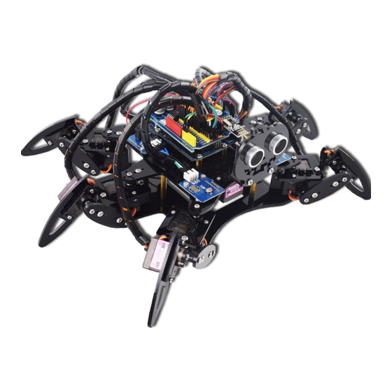
Page 9: About Adeept 6-Leg Spider Robot
The Adeept Arduino UNO R3 board is used as the core control board for this kit, and an Adeept 32 Channel PWM Drive board for control of 19 servos onside.After assembly, you can see 2 parts, the hexapod robot and a remote control. -
Page 10: Functions
When the robot is in remote control mode, it can move forward、backward and turn left or right, and it can shift to the left and right. This function supports remote control of Adeept Remote Control Shield Board, shifting to the left and right can’t be supported by Android APP remote control. - Page 11 Android APP 2. When we use Bluetooth communication( ) we need to modify a parameter in the program, as shown below: Before using android APP, we need to let the phone find the bluetooth module provided by us and conduct the matching operation, so that the android APP provided by us can connect to the robot.
- Page 12 The rocker U1 moves forward and the robot moves forward. Rocker U1 moves backwards, the robot moves backwards. The rocker U2 shifts to the left, and the robot shifts to the left.
-
Page 13: Assembly
Cable x2 Male-Female Cable x2 Effect diagram after assembling Female-Female Cable connects to VCC and GND respectively B. Connect Adeept Passive Buzzer Module to Cable Assemble the following components Adeept Passive Buzzer Module x1 Male-Female Cable x1 Female-Female Cable x2... - Page 14 C. Connect Adeept RGB LED Module to Cable Assemble the following components Adeept RGB LED Module x1 Female-Female Cable x4 Effect diagram after assembling D. Connect Adeept Photoresistor Module to Cable(2 sets). Assemble the following components Adeept Photoresistor Module x1...
-
Page 15: Assemble The Upper Part
Assemble the upper part A. Keep the four M3*6 Copper Standoffs fixed on A01 Assemble the following components M3*6 Copper Standoff is at the same side with LOGO M3*6 Copper Standoff x4 A01 x1 For the convenience of reading,... - Page 16 B. Keep the six M2*8 Screws fixed on A01 Assemble the following components M2 Nut x6 M2*8 Screw x6 Effect diagram after assembling Pay attention to the installation place of M2x8, not to install in a wrong way.
- Page 17 C. Keep the two M3*10 Countersunk Head Screws fixed on 18650x2 Battery Holder-B Assemble the following components M3*10 Countersunk Head Screw x2 18650x2 Battery Holder-B x1 M3 Nut x2 Effect diagram after assembling...
- Page 18 D. Keep 18650x2 Battery Holder fixed on A01 Assemble the following components M3 Nut x2 18650x2 Battery Holder’s wiring is on the right as the picture shown Effect diagram after assembling...
- Page 19 E. Keep the six M3*40 Copper Standoff fixed on A01 Assemble the following components M3*8 Screw x6 M3*40 Copper Standoff x6 Effect diagram after assembling...
- Page 20 Keep the Adeept UNO R3 fixed on M3*6 Copper Standoff Assemble the following components M3*5 Screw x4 Adeept UNO R3 x1 M3*6 Copper Standoff Effect diagram after assembling...
- Page 21 G. Plug Adeept 32 Channel PWM Drive in Adeept UNO R3 Assemble the following components Adeept 32 Channel PWM Drive x1 Effect diagram after assembling...
- Page 22 H. Take a Servo and install on A01 Assemble the following components M2*8 Screw Servo x1 M2 Nut x2 Effect diagram after assembling The rotation axis of servo is After the completion of the on the right as the picture assembly, the wiring of the steering shown.
- Page 23 Effect diagram after assembling After connection is done, switch off the board and install the batteries. J.Connect the wiring of Servo with the port PWM15 on Adeept 32 Channel PWM Drive Servo wiring diagram Now the steering gear has been installed, for the convenience of reading, only wiring is shown here.
- Page 24 K.Plug NRF24L01 in Adeept 32 Channel PWM Drive. Assemble the following components Note that the installation direction of the NRF24L01 cannot be reversed P2 port Effect diagram after assembling...
- Page 25 L.According to the following picture, install the 18650 Battery on 18650x2 Battery Holder. Take out 2 ribbons and 2 batteries. Roll one end of the ribbon to let through a battery and fix. Roll one end of the ribbon to let through a battery and fix.
- Page 26 M. Switch on the power and install the rocker arm on the steering gear. Before switching on the power, we need to check whether Adeept 32 Channel PWM Drive is flush with Adeept UNO R3 The correct result Adeept 32 Channel PWM Drive...
- Page 27 Connect to the power Turn on the switch of the Adeept 32 Channel PWM Drive and wait for the steering gear to turn to its original position before installing the rocker arm. Install the rocker arm on the steering gear with the angle according to the picture shown.
- Page 28 Effect diagram after assembling After the installation Rocker arm, turn the switch on Adeept 32 Channel PWM Drive to OFF (shut OFF the power). At the later installation process,you may not take the rocker from the steering gear, or you have to repeat this step to complete the rocker...
- Page 29 Screw x4 Effect diagram after assembling In the previous installation process, we have connected Adeept Ultrasonic Module and wiring, and for convenient reading, in the subsequent installation process, here all wiring does not display (except the needed display). In the actual installation process, please don't remove the wiring.
- Page 30 P. Fix A09 with A07 Assemble the following components M3 Nut x1 A09 x1 M3*8 Screw x1 Effect diagram after assembling Front view Opposite view...
- Page 31 Q. Fix A07 with steering gear and rocker arm. Assemble the following components When installing, M2.5*8 Screw is Self-tapping screw firstly fixed with the steering gear packaged with servo through A07 , and then self-tapping Screw packaged with servo...
-
Page 32: Install The Right Feet
Install the right feet A. Keep the servo fixed with A04. (3 sets) Assemble the following components Effect diagram after assembling servo x1 Here the gap is on the right M2*8 Screw x1 M2 Nut x1 A04 x1 The steering gear shaft... - Page 33 C. Fix A03 with A04. (3 sets) Assemble the following components Effect diagram after assembling M3*8 Screw x2 M3 Nut x2 Define the component completed in this step as component C1 D. Fix the servo with A06 .(3 sets)
- Page 34 When the servo is connected to the Adeept 32 Channel PWM Drive, turn the switch of the Adeept 32 Channel PWM Drive to "ON" (turn ON the power),and wait for the servo to turn...
- Page 35 F. Install the rocker arm on the steering gear in turn. Install the first rocker arm at the following Angle 90° Here the Angle can be slightly deviated Assemble the following components Effect diagram after assembling rocker arm x1...
- Page 36 Install the second rocker arm at the following Angle 90° Here the Angle can be slightly deviated Assemble the following components Effect diagram after assembling rocker arm x1...
- Page 37 Effect diagram after assembling rocker arm x1 After the three rocker arm installed, turn the switch of Adeept 32 Channel PWM Drive to OFF (power OFF), and unplug the servo wiring from the Adeept 32 Channel PWM Drive. At the later installation process you may not take the rocker from the steering gear, otherwise you need to repeat the above steps to complete the installation of the rocker arm.
- Page 38 G. Fix the A05 with the servo on A04 Assemble the following components Effect diagram after assembling A05 x1 Self-tapping M2.5*8 screw packaged Screw x1 with servo H. Fix the A05 with the servo on A06 Assemble the following components...
- Page 39 I. Install the 3 right feet on A01 in turn. Assemble the following components Self-tapping screw packaged with servo M2.5*8 Screw x1 Right feet Effect diagram after assembling...
- Page 40 The effect diagram after the assembly of three right feet.
-
Page 41: Assemble The Left Feet
Assemble the left feet A. Fix the servo with A04 (3 sets) Assemble the following components Effect diagram after assembling servo x1 The gap here is on the left M2*8 Screw x1 M2 Nut x1 A04 x1 The servo shaft is... - Page 42 C. Fix A03 with A04 (3 sets). Assemble the following components Effect diagram after assembling M3*8 Screw x2 M3 Nut x2 Define the component completed in this step as component C2 D. Fix the servo with A06.(3 sets) Assemble the following components...
- Page 43 When the servo is connected to the Adeept 32 Channel PWM Drive, turn the switch on the Adeept 32 Channel PWM Drive to ON (turn ON the power), wait for the steering gear to...
- Page 44 F. Install the rocker arm on the servo in turn. Install the first rocker arm at the following Angle 90° Here the Angle can be slightly deviated Assemble the following components Effect diagram after assembling rocker arm x1...
- Page 45 Install the second rocker arm at the following Angle 90° Here the Angle can be slightly deviated Assemble the following components Effect diagram after assembling rocker arm x1...
- Page 46 Effect diagram after assembling rocker arm x1 After the three rocker arm installed, turn the switch of Adeept 32 Channel PWM Drive to OFF (power OFF), and unplug the servo wiring from the Adeept 32 Channel PWM Drive. At the later installation process you may not take the rocker from the servo, otherwise you need to repeat the above steps to complete the installation of the rocker arm.
- Page 47 G. Fix A05 with the servo on A04 Assemble the following components Effect diagram after assembling A05 x1 Self-tapping M2.5*8 screw packaged Screw x1 with servo H. Fix A05 with the servo on A06. Assemble the following components Effect diagram after assembling Self-tapping M2.5*8...
- Page 48 I. Install 3 left feet on A01 in turn. Assemble the following components Self-tapping screw packaged with servo M2.5*8 Screw x1 Left feet Effect diagram after assembling...
- Page 49 The effect diagram after the assembly of three left feet...
-
Page 50: Complete The Whole Assembly
Complete the whole assembly A. Fix Adeept Passive Buzzer Module on A01 Assemble the following components Adeept Passive Buzzer Module x1 M2 Nut x2 Fix Adeept Passive Buzzer Module on M2*8 Screw here Effect diagram after assembling... - Page 51 B. Fix Adeept Photoresistor Module on A01 Assemble the following components M2 Nut x2 Fix Adeept Passive Buzzer Module Adeept Photoresistor on M2*8 Screw Module x1 Effect diagram after assembling...
- Page 52 Effect diagram after assembling Fix another Adeept Photoresistor Module on the other side C. Fix the two M2*8 Screws with Adeept RGB LED Module. Assemble the following components Effect diagram after assembling Adeept RGB LED Module x1 M2*8 Screw x2...
- Page 53 D. Fix Adeept RGB LED Module on A02. Assemble the following components A02 x1 M2 Nut x2 Effect diagram after assembling...
- Page 54 A02 with M3*40 Copper Standoff on A01. Assemble the following components M3*8 Screw x6 M3*40 Copper Standoff Effect diagram after assembling A04 goes through the hole on A02.
- Page 55 F. Plug Adeept Bluetooth Module or NRF24L01 in Adeept 32 Channel PWM Drive. Adeept Bluetooth Module and NRF24L01 can’t be inserted in Adeept 32 Channel PWM Drive at the same time,you can choose Adeept Bluetooth Module or NRF24L01 according to your need.
- Page 56 Plug Adeept Bluetooth Module in Adeept 32 Channel PWM Drive. Assemble the following components Note that the installation direction of the Adeept Bluetooth Module cannot be reversed P3 port Effect diagram after assembling...
- Page 57 Plug NRF24L01 in Adeept 32 Channel PWM Drive. Assemble the following components Note that the installation direction of the NRF24L01 cannot be reversed P2 port Effect diagram after assembling...
-
Page 58: Remote Control
Remote Control A. Fix the 18650x2 Battery Holder-A and Adeept Remote Control Shield. Assemble the following components The wiring on the 18650x2 M3*10 Countersunk Battery Holder shall not be Head Screw pressed between the 18650x2 Battery Holder and the Adeept Remote... - Page 59 B. Plug Arduino Nano in Adeept Remote Control Shield. Assemble the following components Arduino Nano x1 Effect diagram after assembling Pay attention to the direction of the Arduino Nano. Do not reverse it.
- Page 60 C. Plug NRF24L01 in Adeept Remote Control Shield. Assemble the following components NRF24L01 x1 Plug NRF24L01 in the port P4 of Adeept Remote Control Shield. Effect diagram after assembling...
-
Page 61: Circuit Connection
Look at Adeept 32 Channel PWM Drive, we can see PWM1 ~ PWM30, PWM31 altogether 32 ports on PWM0 Adeept 32 Channel PWM Drive, and the servo wiring connects to these ports, we will use the port number to number the servos (servo number is correspondent to the port number on Adeept 32 Channel PWM Drive), so that we will be convenient to connect to the servo. - Page 62 B. Connect Adeept Photoresistor Module with Adeept 32 Channel PWM Drive. Adeept Adeept Photoresistor Photoresistor Module -B Module -A...
- Page 63 C. Connect Adeept Ultrasonic Module with Adeept 32 Channel PWM Drive.
- Page 64 D.Connect Adeept RGB LED Module with Adeept 32 Channel PWM Drive.
- Page 65 E.Connect Adeept Passive Buzzer Module with Adeept 32 Channel PWM Drive.
- Page 66 F.Connect 18650x2 Battery Holder with Adeept 32 Channel PWM Drive.
- Page 67 G.Connect 18650x2 Battery Holder with Adeept Remote Control Shield.
-
Page 68: Software & Hardware
Software & Hardware What is Arduino? Arduino is an open-source electronics platform based on easy-to-use hardware and software. Arduino boards are able to read inputs - light on a sensor, a finger on a button, or a Twitter message - and turn it into an output - activating a motor, turning on an LED, publishing something online. -
Page 69: How Should I Use Arduino
Two types of Arduino board are used in this car kit: Adeept UNO R3 board and Arduino Nano board. Power The Arduino/Genuino Uno board can be powered via the USB connection or with an external power supply. -
Page 70: Arduino Software (Ide)
Input and Output Each of the 14 digital pins on the Uno can be used as an input or output, using pinMode(), digitalWrite(), and digitalRead() functions. They operate at 5 volts. Each pin can provide or receive 20 mA as recommended operating condition and has an internal pull-up resistor (disconnected by default) of 20-50k ohm. - Page 71 After the download completes, run the installer. For Windows users, there may pop up an installation dialog box of the driver during the installation. Please agree the installation when it appears. After installation is completed, an Arduino software shortcut will be generated on the desktop.
- Page 72 The interface of Arduino software is as follows: The Arduino Integrated Development Environment - or Arduino Software (IDE) - contains a text editor for writing code, a message area, a text console, a toolbar with buttons for common functions and a series of menus. It connects to the Arduino and Genuino hardware to upload programs and communicate with them.
-
Page 73: Install Library
When you upload a sketch, you're using the Arduino bootloader, a small program that has been loaded on to the microcontroller on your board. It allows you to upload code without using any additional hardware. The bootloader is active for a few seconds when the board resets; then it starts whichever sketch was most recently uploaded to the microcontroller. - Page 74 After the library is installed successfully, you can find the RF24.ZIP, AdeeptDistance.ZIP and Adeept_PWMPCA9685.ZIP under Sketchbook location: on the window popped up by clicking Preferences.
- Page 75 www.adeept.com...
-
Page 76: Upload Program
After the preparations above, next we will upload the program (example sketches provided) to the Arduino Nano and Adeept UNO R3 boards. The Robots kit comprises of two parts: the remote control based on Arduino Nano and the Robots controller on Adeept UNO R3. - Page 77 www.adeept.com...
- Page 78 Next, click the upload button . After the program is uploaded to the Nano successfully, upload another sketch to the Adeept UNO R3. Open the program provided for the control board, the file “Adeept6LegSpiderRobot.ino”. Connect the Arduino UNO R3 board to the PC. Select Tool -> Board “Arduino/Genuino Uno”, and...
- Page 79 Click the button to upload the sketch to the board.
- Page 80 Note: turn on the power switch of the robot at this time, if each leg of robot stands at 90 degrees, then there is no need to debug the following parameters, the correct position of the robot on each leg as shown in the figure below :...
- Page 81 If you find that the legs of robot is high and low, it’s not we have expected that each joint stands at 90 degrees. So this requires us to modify the following parameters (in the Adeept6LegSpiderRobot.ino) to adjust the initial Angle of each leg and each joint. These...
-
Page 82: Afterword
After completing all projects in the guide, you should have some knowledge of the book and Arduino, thus you can try to change the robot into other projects by adding more Adeept modules or changing the code for extended functions. - Page 83 www.adeept.com...
Need help?
Do you have a question about the Hexapod 6 Legs Spider Robot and is the answer not in the manual?
Questions and answers